1
1.0 DESIGN
1.2 TECHNICAL DATA
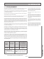
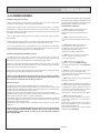
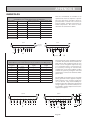
Sensor Tempature Readings
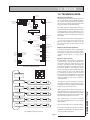
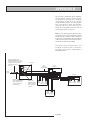
Details of the various sensors S1-S6 used in
the BoilerMate A-Class are shown opposite.
The sensor reference i.e. S1 and the actual
temperature at that sensor flash alternately on
the display when selected.
Sensors used in BoilerMate A-Class
Sensor
Sensor
Connector J9 pins
Location
S1
T Overheat 1
6 & 14
S2
T Overheat 2
2 & 10
S3
T DHW in
3 & 11
In cold water inlet pipe (Wet i.e. direct)
S4
T DHW out
4 & 12
In hot water outlet pipe (Wet i.e. direct)
S5
T Tank bottom
5 & 13
Bottom of store in dry pocket for store charging
S6
T Tank middle
1&9
Middle of store in dry pocket for store charging
Top of store in dry pocket (S1 & S2 are in single housing)
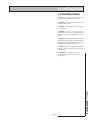
Control Set Points
Sensor Control Set Points
Display
Sensor
Temp
S1
Middle store sensor on
68
S2
Middle store sensor off
77
S3
DHW in
35
S4
DHW out
55
S5
Bottom store sensor on
60
S6
Bottom store sensor off
70
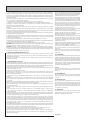
Common Fault Codes
Code
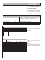
The sensor control set points are shown
opposite. PLEASE NOTE THAT THE DISPLAY
S1 - S6 IS NOT THE SAME AS THE SENSOR
REFERENCE.
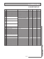
Fault Codes
Code
10
Overheat error
45
S1 overheat 1 shorted
30
Phase error
48
I.D. resistor shorted
33
Appliance selection
49
S4 sensor shorted
37
S1 overheat 1 open
50
S5 sensor shorted
40
I.D. resistor open
51
S6 sensor shorted
41
S4 sensor open
52
S2 overheat 2 shorted
42
S5 sensor open
43
S6 sensor open
44
S2 overheat 2 open
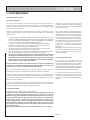
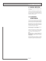
Fault code locations are numbered C0 - CF
and c0 - cF.
CO/cO locations hold the latest fault recorded.
A code of FF indicates that the fault location
is empty.
If a sensor is faulty instead of a temperature
it will show E1 if open circuit and E2 if short
circuit.
Any other code displayed should be checked against the full chart
Page 10