1
OC185A--1.qxp 1.12.19 10:23 AM Page 1
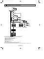
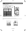
PK18FL,
PK24FL,
PK30FL,
PK36FL,
PK18FL1
PK24FL1
PK30FL1
PK36FL1
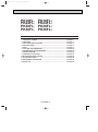
CONTENTS
1. TECHNICAL CHANGE················································································OC185A- 1
2. FEATURES ··································································································OC185A- 2
3. PART NAME AND FUNCTIONS ·································································OC185A- 3
4. SPECIFICATIONS ·······················································································OC185A- 4
5. DATA············································································································OC185A- 5
6. OUTLINES AND DIMENSIONS ··································································OC185A-12
7. REFRIGERANT SYSTEM DIAGRAM ·························································OC185A-14
8. WIRING DIAGRAM······················································································OC185A-15
9. OPERATION FLOW-CHART·······································································OC185A-16
10. MICROPROCESSOR CONTROL ·······························································OC185A-19
11. TROUBLESHOOTING ·················································································OC185A-28
12. DISASSEMBLY PROCEDURE····································································OC185A-31
13. PARTS LIST·································································································OC185A-34
OC185A-1
OC185A--1.qxp 1.12.19 10:23 AM Page 2
1
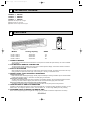
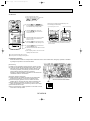
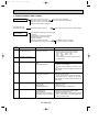
TECHNICAL CHANGE
PK18FL ➔
PK24FL ➔
PK30FL ➔
PK36FL ➔
PK18FL1
PK24FL1
PK30FL1
PK36FL1
● DRAIN PAN shape has changed.
● NOSE shape has changed.
● UNDER PLATE shape has changed.
2
FEATURES
SET TEMP
COOL
DRY
˚F
FAN
SWING
AM
PM
FAN
ON
OFF
AM
PM
NOT AVAILABLE
POWER ON / OFF
TEMP
Indoor unit
Models
PK18FL,
PK24FL,
PK30FL,
PK36FL,
Wireless Remote controller
Cooling capacity
PK18FL1
PK24FL1
PK30FL1
PK36FL1
18,500
24,000
30,000
34,200
SEER
Btu/h
Btu/h
Btu/h
Btu/h
11.3
10.6
10.7
10.2
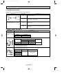
1. COMPACT DESIGN
The PK series models have been downsized and now require such minimal wall space that they can even be installed
above windows.
2. LCD WIRELESS REMOTE CONTROLLER
The new wireless remote controller has a larger easy-to-read temperature display, and executes ON/OFF commands
and temperature settings with a press of the button.
3. AUTO FLAP SHUTTER
With a simple flick of the OFF switch the air outlet can be closed off with a shutter. The shutter also functions as a flap
during operation to adjust the air flow angle, with “Auto Angle 1” securing a comfortable air flow.
4. INSTALLATION : FAST AND EASILY ADAPTABLE
(1) Multi-directional piping
Multi directional drain and refrigerant piping radically improves flexibility in selecting installation layouts. PK18/24/30/36
models boast refrigerant piping in 4 directions and drain piping in 2 directions.
(2) Back plate installation guide
The back plate installation guide gives clear instructions on installation positions. The enlarged back plate secures the
unit firmly to the wall, while the support piece which lifts the unit makes left side piping work much easier.
(3) Easily removable filter and convenient wireless remote controller
The presence of thumb screws on the filters means that the filters can be quickly and smoothly removed.
5. HIGH RELIABILITY AND EASY SERVICING
In addition to the self-diagnostic function, units are also equipped with a 3-minute time delay mechanism (cooling), an auto
restart function, an emergency operation function, a test run switch, etc., to assure high reliability and easy servicing.
6. NITROGEN GAS IS CHARGED TO INDOOR UNIT
Indoor unit and refrigerant pipes are charged with nitrogen gas (N2) instead of R22 before shipment from the factory.
OC185A-2
OC185A--1.qxp 1.12.19 10:23 AM Page 3
3
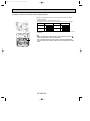
PART NAME AND FUNCTIONS
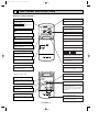
Wireless remote controller
OPERATION MODE display
85°F display
Operation mode display indicates which operation mode is in effect.
• CHECK • TEST RUN display
CHECK&TEST RUN display indicates that the
unit is being checked or test-run.
SET TEMP. display indicates desired temperature set.
SET TEMP
COOL
DRY
DIsplays the current time.
AM
PM
FAN
OFF
ON
Displays when batteries are dead.
display
AM
PM
“
NOT AVAILABLE
”display
Flashes when the current time is displayed.
POWER ON / OFF
Timer setting display
Displays when setting timer.
Displays when in timer operation or when setting timer.
display
➡
Lights when signal is sent from the remote
controller to the indoor unit.
“
TEMP
➡
display
CLOCK display
˚F
FAN
SWING
”“
” display
Displays the order of timer operation.
FAN SPEED display
“ ▼ ON ” “ ▲ OFF ” display
FAN SPEED display indicates which fan speed
has been selected.
Displays the selected timer function.
(ON timer function or OFF timer function).
▼
This displays the air direction
▼
AIR DISCHARGE display
display
Displays when the current time and the timer
time can be changed.
SET TEMPERATURE button
ON/OFF button
Used to change the set temperature setting
range: cooling 65°F to 87°F
The unit is turned ON and OFF alternately
each time the button is pressed.
NOT AVAILABLE
● When cover is open.
MODE SELECT button
POWER ON / OFF
Button used to set the current time.
MODE
MODE SELECT button is used to change
cooling, dry (dehumidify) and ventilation operation modes.
FAN
CLOCK
TIMER SET
VANE
FAN SPEED SELECT button
SET CLOCK button
STOP
START
HR
MIN.
FAN SPEED SELECT button selects low or
high fan speed.
TIMER CONTROL buttons
STOP (OFF timer): when this switch is set,
the air conditioner will be automatically
stopped at the preset time.
START (ON timer): when this switch is set, the
air conditioner will be automatically started at
the preset time.
AIR DISCHARGE button
HR. and MIN.buttons
AIR DISCHARGE button regulates the vertical
distribution of airflow.
Buttons used to set the “hour and minute” of
the current time and timer time.
OC185A-3
OC185A--1.qxp 1.12.19 10:23 AM Page 4
4
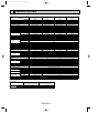
SPECIFICATIONS
Model
Item
Btu/h
❈1
Capacity
kW
❈1
Power consumption
❈1
EER
SEER
INDOOR UNIT MODEL
External finish
V, Phase, Hz
Power supply
A
Max. fuse size (time delay)
A
Min ampacity
F.L.A.
Fan motor
CFM
Dry
Airflow Hi-Lo
CFM
Wet
Pints/h
Moisture removal
dB
Sound level Hi-Lo
in.
Unit drain pipe I.D.
in.
W
in.
D
Dimensions
in.
H
Ib.
Weight
OUTDOOR UNIT MODEL
External finish
V, Phase, Hz
Power supply
A
Max. fuse size (time delay)
A
Min. ampacity
F.L.A
Fan motor
Model
R.L.A
Compressor
L.R.A
A(W)
Crankcase heater
Refrigerant control
dB
Sound level
in.
W
in.
D
Dimensions
in.
H
Ib.
Weight
REMOTE CONTROLLER
Control voltage (by built-in transformer)
REFRIGERANT PIPING
in.
Liquid
Pipe size
in.
Gas
Indoors
Connection method
Outdoors
ft
Height
Between the indoor
fr
Piping length
& outdoor units
–
Refrigerant charge
cc <Model>
Refrigerant oil
PK18FL
PK18FL1
PK30FL
PK30FL1
PK24FL
PK24FL1
18,500
1.75
10.6
11.3
PK18FL, PK18FL1
PK36FL
PK36FL1
24,000
30,000
2.34
3.06
10.3
9.8
10.6
10.7
PK24FL, PK24FL1
PK30FL, PK30FL1
Munsell 3.4Y7.7/0.8
115, 1, 60
15
15
1
2
0.7
1.0
710-530
990-780
640-480
890-700
7.2
9.6
48-41
49-44
1-1/16
1-1/16
15
1
0.7
710-530
640-480
5.3
48-41
1-1/16
55-1/8
34,200
3.47
9.9
10.2
PK36FL, PK36FL1
15
2
1.0
990-780
890-700
10.5
49-44
1-1/16
66-5/32
9-1/4
13-3/8
53
PU18EK1
53
PU24EK1
62
PU30EK1
62
PU36EK1
Munsell 5Y7/1
208/230, 1, 60
20
16
0.75
RH247NAB
12.0
37
0.11/0.12 (23/28)
20
30
16
20
0.65+0.65
0.65+0.65
NH33NBD
NH41NAD
11.5
14.0
54
73
0.16/0.17 (33/39)
0.16/0.17 (33/39)
Capillary tube
55
55
34-1/4
11-5/8
49-9/16
207
208
With indoor unit
Indoor unit - outdoor unit : DC12V
Not supplied (optional parts)
53
33-1/2
154
3/8
5/8
30
22
0.75+0.75
NH47NAD
17.5
87
0.16/0.17 (33/39)
55
38-3/16
13-9/16
220
1/2
3/4
Flared
Flared
130
130
5 lbs 8 oz
520 <MS-56>
9 lbs 15 oz
1200 <MS32N-1>
NOTES : ❈ 1.Rating conditions —indoor : 80˚FDB, 67˚FWB outdoor : 95˚FDB,75˚FWB.
Operating range
Indoor intake air temperature
Outdoor intake air temperature
Maximum
95˚FDB, 71˚FWB
115˚FDB
Cooling
Minimum
67˚FDB, 57˚FWB
0˚FDB *
In case of the wind baffle is installed.
*
(In case of the wind baffle is not installed, the minimum temperature will be 23˚FDB.)
OC185A-4
164
164
10 lbs 2 oz
10 lbs 9 oz
1300 <MS32N-1>
OC185A--1.qxp 1.12.19 10:23 AM Page 5
5
DATA
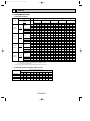
1. PERFORMANCE DATA
1) COOLING CAPACITY
Outdoor intake air DB temperature (˚F)
Indoor air
75
Airflow
Models
(˚F)
PK18FL1
0.14
TPC
TC
SHC
TPC
TC
SHC
TPC
TC
SHC
TPC
TC
SHC
TPC
71
21.5
14.8
1.52
20.8
14.3
1.65
19.9
13.7
1.80
19.0
13.0
1.95
18.1
12.4
2.10
67
20.1
16.5
1.49
19.3
15.8
1.61
18.5
15.2
1.75
17.6
14.4
1.89
16.7
13.7
2.03
63
18.8
17.9
1.46
18.0
17.2
1.57
17.2
16.4
1.70
16.4
15.6
1.83
15.5
14.8
1.96
DB75˚F(50%RH)
62.5
18.6
16.0
1.45
17.9
15.4
1.57
17.1
14.7
1.70
16.2
13.9
1.83
15.4
13.2
1.96
DB72˚F(50%RH)
60
17.8
15.6
1.43
17.1
15.0
1.55
16.3
14.3
1.67
15.5
13.6
1.79
14.6
12.8
1.92
DB70˚F(50%RH)
59
17.4
15.0
1.43
16.7
14.4
1.54
16.0
13.8
1.66
15.1
13.1
1.78
14.3
12.4
1.90
71
27.9
16.4
2.04
26.9
15.8
2.21
25.8
15.1
2.40
24.6
14.4
2.61
23.4
13.7
2.81
67
26.1
18.8
1.99
25.1
18.1
2.16
24.0
17.3
2.34
22.9
16.5
2.53
21.7
15.6
2.71
63
24.3
20.7
1.95
23.4
20.0
2.11
22.4
19.1
2.28
21.3
18.2
2.45
20.1
17.2
2.62
DB75˚F(50%RH)
62.5
24.1
18.3
1.94
23.2
17.6
2.10
22.2
16.8
2.27
21.1
16.0
2.44
19.9
15.1
2.62
DB72˚F(50%RH)
60
23.0
17.8
1.92
22.1
17.1
2.07
21.1
16.4
2.23
20.0
15.5
2.40
18.9
14.7
2.56
DB70˚F(50%RH)
59
22.6
17.3
1.91
21.7
16.6
2.05
20.7
15.8
2.22
19.6
15.0
2.38
18.5
14.1
2.54
71
34.9
21.5
2.66
33.7
20.8
2.89
32.3
19.9
3.14
30.8
19.0
3.41
29.3
18.1
3.68
67
32.6
24.5
2.61
31.4
23.6
2.82
30.0
22.5
3.06
28.6
21.5
3.30
27.1
20.3
3.54
63
30.4
26.9
2.55
29.2
25.8
2.75
27.9
24.6
2.98
26.6
23.5
3.21
25.1
22.2
3.43
DB75˚F(50%RH)
62.5
30.2
23.8
2.54
29.0
22.9
2.75
27.7
21.9
2.97
26.3
20.7
3.20
24.9
19.6
3.42
DB72˚F(50%RH)
60
28.8
23.2
2.51
27.7
22.3
2.70
26.4
21.3
2.92
25.1
20.2
3.14
23.7
19.1
3.35
DB70˚F(50%RH)
59
28.3
22.5
2.49
27.1
21.5
2.69
25.9
20.6
2.90
24.6
19.5
3.11
23.2
18.4
3.32
71
39.8
23.0
3.02
38.4
22.1
3.28
36.8
21.2
3.57
35.1
20.2
3.87
33.4
19.3
4.17
67
37.1
26.3
2.96
35.7
25.3
3.20
34.2
24.3
3.47
32.6
23.1
3.74
30.9
21.9
4.02
63
34.7
29.3
2.89
33.3
28.1
3.12
31.9
26.9
3.38
30.3
25.6
3.64
28.7
24.2
3.89
DB75˚F(50%RH)
62.5
34.4
25.8
2.88
33.1
24.8
3.11
31.6
23.7
3.37
30.0
22.5
3.63
28.4
21.3
3.88
DB72˚F(50%RH)
60
32.8
25.1
2.84
31.5
24.1
3.07
30.1
23.0
3.31
28.6
21.9
3.56
27.0
20.7
3.80
DB70˚F(50%RH)
59
32.2
24.3
2.83
30.9
23.3
3.05
29.5
22.3
3.29
28.0
21.1
3.53
26.4
19.9
3.77
DB 80˚F
PK24FL
710
PK24FL1
0.14
DB 80˚F
PK30FL
990
PK30FL1
0.15
DB 80˚F
PK36FL
990
PK36FL1
0.15
115
105
SHC
DB 80˚F
710
95
TC
B.F
PK18FL
85
IWB
(CFM)
Notes 1. B.F. : Bypass Factor, IWB : Intake air wet-bulb temperature
TC : Total Capacity (x103 Btu/h), SHC : Sensible Heat Capacity (x103 Btu/h)
TPC : Total Power Consumption (kW)
2. Cooling capacity correction factors and Refrigerant piping length (one way) range.
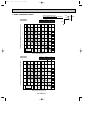
2) COOLING CAPACITY CORRECTIONS FACTOR
Refrigerant piping length (one way)
MODEL
25ft
40ft
55ft
70ft
85ft
100ft
115ft
130ft
150ft
164ft
PK18FL, PK18FL1
1.0
0.992
0.983
0.978
0.966
0.959
0.950
0.945
—
—
PK24FL, PK24FL1
1.0
0.981
0.968
0.952
0.940
0.925
0.913
0.900
0.886
0.874
PK30FL, PK30FL1
1.0
0.981
0.968
0.952
0.940
0.925
0.913
0.900
0.886
0.874
PK36FL, PK36FL1
1.0
0.981
0.968
0.952
0.940
0.925
0.913
0.900
0.886
0.874
OC185A-5
OC185A--1.qxp 1.12.19 10:23 AM Page 6
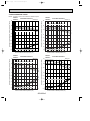
2. PERFORMANCE CURVE
NOTE : A point on the curve shows the reference point.
PK18FL
COOLING CAPACITY
PK18FL1
SHF=0.82
24
71
67
63
18
indoor intake air WB temperature (°F)
12
3.0
2.5
71
67
63
2.0
1.5
1.0
023 3235
indoor intake air WB temperature (°F)
45
55
65(67) 75
85
95
105
30
24
71
67
63
18
3.5
71
3.0
67
63
2.5
2.0
indoor intake air WB temperature (°F)
1.5
0 23 32 35 45 55 65 (67) 75 85 95
115
PK36FL
PK36FL1
COOLING CAPACITY
SHF=0.75
36
71
67
63
24
4.0
71
67
63
3.5
3.0
2.5
indoor intake air WB temperature (°F)
2.0
0 23 32 35 45 55 65 (67) 75 85 95
COOLING CAPACITY
SHF=0.71
42
indoor intake air WB temperature (°F)
30
105 115
Outdoor intake air DB temperature (°F)
105 115
Total power consumption (kW) Total capacity (✕103 Btu/h)
Total power consumption (kW) Total capacity (✕103 Btu/h)
42
SHF=0.72
indoor intake air WB temperature (°F)
Outdoor intake air DB temperature (°F)
PK30FL
PK30FL1
COOLING CAPACITY
36
Total power consumption (kW) Total capacity (✕103 Btu/h)
30
Total power consumption (kW) Total capacity (✕103 Btu/h)
PK24FL
PK24FL1
36
71
67
30
indoor intake air WB temperature (°F)
63
indoor intake air WB temperature (°F)
71
67
63
24
4.5
4.0
3.5
3.0
2.5
023 3235
Outdoor intake air DB temperature (°F)
45
55
65(67) 75
85
95
Outdoor intake air DB temperature (°F)
OC185A-6
105
115
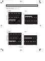
OC185A--1.qxp 1.12.19 10:23 AM Page 7
Condensing pressure
<Cooling mode>
PK24FL
[psi.G] PK24FL1
350
340
330
320
310
300
290
280
270
260
250
240
230
220
210 Indoor DB temperature (°F)
200
190
180
170
160
150
30
40
50 60 70
80 90
Outdoor ambient temperature
PK18FL
PK18FL1
86
80
75
70
[psi.G]
100
86
80
75
70
90
Indoor DB temperature (°F)
80
Suction pressure
<Cooling mode>
PK18FL
[psi.G] PK18FL1
360
350
340
330
320
310
300
290
280
270
260
250
240
230 Indoor DB temperature (°F)
220
210
200
190
180
170
160
30
40
50 60 70
80 90
Outdoor ambient temperature
70
60
50
40
30
20
100 110
DB(°F)
30
40
50 60 70
80 90
Outdoor ambient temperature
100 110
DB(°F)
PK24FL
PK24FL1
86
80
75
70
[psi.G]
100
90
Suction pressure
Condensing pressure
Data is based on the condition of indoor humidity 50%.
Air flow should be set at HI.
A point on the curve shows the reference point.
80
Indoor DB temperature (°F)
70
86
80
75
70
60
50
40
30
100 110
DB(°F)
OC185A-7
20
30
40
50 60 70
80 90
Outdoor ambient temperature
100 110
DB(°F)
OC185A--1.qxp 1.12.19 10:23 AM Page 8
Data is based on the condition of indoor humidity 50%.
Air flow should be set at HI.
A point on the curve shows the reference point.
PK30FL
PK30FL1
86
80
75
70
Condensing pressure
<Cooling mode>
PK30FL
[psi. G] PK30FL1
340
330
320
310
300
290
Indoor DB temperature (°F)
280
270
260
250
240
230
220
210
200
190
180
170
160
150
140
30 40 50 60 70 80 90
[psi.G]
100
Suction pressure
90
80
70
60
50
40
30
30
100 110
DB(°F)
Outdoor ambient temperature (°F)
100 110
DB(°F)
Outdoor ambient temperature (°F)
40
50
60
70
80
90
100 110
DB(°F)
Outdoor ambient temperature (°F)
PK36FL
PK36FL1
86
80
75
70
[psi. G]
Indoor DB temperature (°F)
90
80
Suction pressure
Condensing pressure
<Cooling mode>
PK36FL
[psi. G] PK36FL1
340
330
320
310
300
290
280
270
260
250
240
230
220
210
200
190
180
170
160
Indoor DB temperature (°F)
150
140
30 40 50 60 70 80 90
86
80
75
70
Indoor DB temperature (°F)
70
60
50
40
30
20
30
OC185A-8
40
50
60
70
80
90
100 110
DB(°F)
Outdoor ambient temperature (°F)
86
80
75
70
OC185A--1.qxp 1.12.19 10:23 AM Page 9
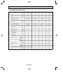
3. STANDARD OPERATION DATA
Model
PK18FL, PK18FL1
PK24FL, PK24FL1
PK30FL, PK30FL1
PK36FL, PK36FL1
Unit
Cooling
Cooling
Cooling
Cooling
Btu / h
18,500
24,000
30,000
34,200
SHF
—
0.82
0.72
0.75
0.71
Input
kW
1.75
2.34
3.06
3.47
PK18FL, PK18FL1
PK24FL, PK24FL1
PK30FL, PK30FL1
PK36FL, PK36FL1
115, 1, 60
115, 1, 60
115, 1, 60
115, 1, 60
0.09
0.09
0.12
0.12
Item
Total
Capacity
INDOOR UNIT MODEL
Power supply (V, phase, Hz)
Electrical circuit
Input
kW
0.7
0.7
1.0
1.0
PU18EK1
PU24EK1
PU30EK1
PU36EK1
208/230, 1, 60
208/230, 1, 60
208/230, 1, 60
208/230, 1, 60
kW
1.66
2.25
2.94
3.35
Comp. current
A
12.0
11.5
14.0
17.5
Fan current
A
0.75
0.65+0.65
0.65+0.65
0.75+0.75
Condensing pressure
psi-G
255
240
247
247
Suction pressure
psi-G
82
74
77
73
Discharge temp.
˚F
171
155
163
163
Condensing temp.
˚F
118
114
116
116
Suction temp.
˚F
51
44
46
43
Ref. pipe length
ft
25
25
25
25
DB
˚F
80
80
80
80
WB
˚F
67
67
67
67
DB
˚F
61
58
59
58
WB
˚F
59
56
58
56
Fan speed (High)
rpm
1,300
1,300
1,380
1,380
Airflow (High)
CFM
710
710
990
990
DB
˚F
95
95
95
95
WB
˚F
75
75
75
75
Fan speed upper / lower
rpm
790
Airflow
CFM
1,590
Fan current
A
OUTDOOR UNIT MODEL
Power supply (V, phase, Hz)
Refrigerant circuit
Input
Outdoor side
Indoor side
Intake air temperature
Discharge air temperature
Intake air temperature
OC185A-9
750
750
3,170
750
750
3,170
760
760
3,350
OC185A--1.qxp 1.12.19 10:23 AM Page 10
4. OPERATING RANGE
1) POWER SUPPLY
Rating
Allowable voltage
Indoor unit
115V 1 phase 60Hz
Min. 103V — Max. 127V
Outdoor unit
208/230V 1 phase 60Hz
Min. 198V — Max. 253V
2) OPERATION
Intake air temperature
Outdoor
Indoor
Function
D.B. (˚F)
W.B. (˚F)
D.B. (˚F)
W.B. (˚F)
Standard temperature
80
67
95
75
Maximum temperature
95
71
115
75
Minimum temperature
67
57
*0
—
Maximum humidity
80
75
80
75
Condition
Cooling
* With wind baffle D.B. 23°F if no wind baffle.
5. OUTLET AIR SPEED AND COVERAGE RANGE
Standard
PK18FL, PK18FL1
PK24FL, PK24FL1
PK30FL, PK30FL1
PK36FL, PK36FL1
(CFM)
710
710
990
990
(ft / sec.)
16.1
16.1
17.7
17.7
41
41
50
50
Airflow
height
Air speed
(8.2ft)
Coverage range
(ft)
● The air coverage range is the value up to the position where the air speed is 0.8ft/sec. when air is blown out
horizontally from the unit at the High fan setting.
The coverage range should be used only as a general guideline since it varies according to the size of the
room and furniture installed inside the room.
6. ADDITIONAL REFRIGERANT CHARGE (R22 (OZ))
Model
Outdoor unit
precharged
(up to 100ft)
25ft
40ft
55ft
70ft
85ft
100ft
115ft
130ft
150ft
164ft
PK18FL,PK18FL1
5 lbs 8 oz
0
0
0
0
0
0
2
4
—
—
PK24FL,PK24FL1
9 lbs 15 oz
0
0
0
0
0
0
2
4
7
9
PK30FL,PK30FL1
10 lbs 2 oz
0
0
0
0
0
0
5
10
16
20
PK36FL,PK36FL1
10 lbs 9 oz
0
0
0
0
0
0
5
10
16
20
Refrigerant piping length (over way)
OC185A-10
OC185A--1.qxp 1.12.19 10:23 AM Page 11
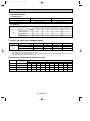
7. NOISE CRITERION CURVES
Ambient temperature 80˚F
Test conditions are based on JIS Z8731
PK18/24FL
PK18/24FL1
NOTCH
SPL(dB)
Hi
48
Lo
41
LINE
3.3ft
OCTAVE BAND SOUND PRESSURE LEVEL, dB re 0.0002 MICRO BAR
90
80
70
NC-70
60
NC-60
50
NC-50
40
NC-40
30
NC-30
20
10
APPROXIMATE
THRESHOLD OF
HEARING FOR
CONTINUOUS
NOISE
63
125
NC-20
250
500
1000
2000
4000
8000
BAND CENTER FREQUENCIES, Hz
PK30/36FL
PK30/36FL1
NOTCH
SPL(dB)
Hi
49
Lo
44
LINE
OCTAVE BAND SOUND PRESSURE LEVEL, dB re 0.0002 MICRO BAR
90
80
70
NC-70
60
NC-60
50
NC-50
40
NC-40
30
NC-30
20
10
APPROXIMATE
THRESHOLD OF
HEARING FOR
CONTINUOUS
NOISE
63
125
NC-20
250
500
1000
2000
BAND CENTER FREQUENCIES, Hz
OC185A-11
4000
8000
Unit
Wall
3.3ft
OC185A-12
Wall fixture
1-17/32
32-{15/32
hole for bolt
B
8-27/32
23/32
3-27/32
1-15/32
2-29/32
A
1-3/16
Knock out hole for piping
66-{1/4 hole for
tapping screw
3-15/16
5/32 1-17/32
1-15/32
2-9/16
7-3/32
12-{1/4 Hole for
tapping screw
9-7/16
on left-hand side
12-3/8
2-3/8
42-15/16
Air outlet
Liquid pipe
Refrigerant pipe. Drain pipe
(Cool)
9-1/4
Terminal block for control
9-7/16
B
MITSUBISHI
ELECTRIC
4-1/32
4-3/8
Liquid pipe 3/8F
Gas pipe 5/8F
Terminal block for power supply
Gas pipe
Drain hose
Bolt
19/32
C
Knock out hole for right piping
Refrigerant pipe. Drain pipe
Emergency switch
POWER
ON
OFF
Power lamp
Receiving section
Right side
ON
2-5/32
4-23/32 (Gas pipe)
7-7/32 (Liquid pipe)
Change vane (manual)
Under panel
Removable at left-hand
side piping
Knock out hole for under-piping
44-3/32
21-23/32
Auto vane
Lower side
Drain hose
Air intake
55-1/8
Front
9-1/4
1-25/32
9-1/4
1-25/32
2-15/32
1/2
Top
43-11/16
9-1/4
1-25/32
21-23/32 Air outlet
9-1/4
3-17/32 Rear piping opening
3-19/32
Range for left rear piping opening
11-1/32
24
on right-hand side
11-7/32
3/4
17-29/32
10x3-19/32=(35-13/16)
35-7/16
Drainage range
23/32 Drainage range
Drain hose for 31/32
left-hand side piping
Knock out hole for
left piping
9-21/32
Unit center
1-15/32
1-17/32
5/32 3-15/16
38-31/32
2-9/16
2-29/32
C
1-3/16
A
Left side
13-3/8
13/32
1-3/16
1-5/32
1. Indoor Unit
PK18/24FL
PK18/24FL1
1-21/32
2-9/32
6
1-3/18 7-1/4
1-3/16
3-5/32
11-1/32
7-3/4
Display section
OC185A--1.qxp 1.12.19 10:23 AM Page 12
OUTLINES AND DIMENSIONS
Unit : inch
3-15/16
1-17/32
for bolt
2-9/16
C
1-17/32
A
35-7/16
29-17/32
11-1/32
3-19/32
23-7/16
13x3-19/32=(7-3/16)
7-3/32
Range for left rear piping hole
rear piping hole
50
Unit center
1-15/32
1-3/16
2-29/32
9-7/16
2-9/16
1-15/32
Range for left
8-27/32
23/32
Wall fixture
23/32
11-5/8
B
3-27/32
Unit out line
Left hand side
41- 15/32 hole
screw
for tapping
1-17/32
1-15/32
Knock out hole for wiring
Drainage range on
2-29/32
1-3/16
A
84- 1/4 hole
5/32
3-15/16
5/32
Rear piping hole
12-3/8
3/4
11-7/32
9-21/32
right-hand side
Drainage range on
Drain hose for
left-hand side piping
31/32
for left piping
Knock out hole
Left side
1-3/16
1-5/32
for tapping screw
12- 1/4 hole
7-17/32
9-1/4
11-1/32
66-5/32
Front
27-5/16 Air outlet
1-25/32
9-1/4
louvers (manual)
27-5/16 Air outlet
Lower side
Auto vanes
7-7/32
Refrigerant pipe .Drain pipe
Knock out hole for under-piping
left-hand piping)
Under panel (Removable at
55-1/8
1
Terminal block for power supply
Drain hose
9-1/4
1-25/32
Terminal block for control
53-15/16 Air Intake
1-25/32
9-1/4
43-11/16 (Drain hose)
1-25/32
9-1/4
2
Knock out hole
for right piping
19/32
or less
9-7/16
B
2-5/32(Gas pipe)
4-23/32(Liquid pipe)
2-9/32
Top
2-15/32
1/2
1-21/32
13-3/8
13/32
7-1/4
1-3/16
OC185A-13
1-3/16
3-5/32
9-1/4
MITSUBISHI
ELECTRIC
4-3/8
4-1/32
Bolt
C
Emergency switch
POWER
ON
OFF
(Cool)
Right side
ON
Power lamp
Receiving section
3-1/2~
>
< 1 Sleeves are available
in the market.
3-1/2
4
Through hole
1/2F
3/4F
Liquid pipe
Gas pipe
Sleeve >
<1
1
2
PK30/36FL
PK30/36FL1
2-3/8
7-3/4
Display section
OC185A--1.qxp 1.12.19 10:23 AM Page 13
Unit : inch
OC185A--1.qxp 1.12.19 10:23 AM Page 14
Unit : inch
2. Remote controller
WIRELESS REMOTE CONTROLLER
2-1/4
SET TEMP
DRY
˚F
FAN
SWING
AM
PM
FAN
ON
OFF
1/8 23/32
COOL
AM
PM
NOT AVAILABLE
6-1/32
POWER ON / OFF
TEMP
2-5/32
7
REFRIGERANT SYSTEM DIAGRAM
PK18/24FL
PK18/24FL1
PK30/36FL
PK30/36FL1
Indoor unit
Indoor
heat
exchanger
Pipe temperature
thermistor
RT2
Refrigerant pipe
(Option)
{5/8
(with heat insulator)
Indoor unit
Indoor
heat
exchanger
Pipe temperature
thermistor
RT2
Refrigerant flow
COOLING
Refrigerant pipe
(Option)
{3/4
(with heat insulator)
Distributor
Distributor
Refrigerant pipe
(Option)
{1/2
(with heat insulator)
Refrigerant pipe
(Option)
{3/8
(with heat insulator)
OC185A-14
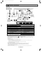
OC185A--1.qxp 1.12.19 10:23 AM Page 15
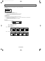
8
WIRING DIAGRAM
Indoor Unit
PK18/24/30/36FL
PK18/24/30/36FL1
L1
N
GR
GRN/YLW
10.6VAC
MF
POWER SUPPLY
~(1 PHASE)
AC115V 60Hz
GROUND
TB2
115V
7
14.5VAC
C
1 3 CNT
TRANS
1 3
F2
F1
7
W.R
SW1
ORN
YLW
REMOTE
CONTROLLER
TB4
2
1
TO OUTDOOR UNIT
CONNECTING WIRES
DC12V
RT2
RT1
CN28
12345678 12345
MODELS
CN20
INTAKE
CN2
1 2 3 4 5
PIPE
TIMER
TWIN-2 TWIN-1
CN70
SW2 WIRELESS
CN21
DRAIN
CN27
SW1
CN50
1
D.U.M
ON
OFF
3 2 1
1 2 3 4 5
SW3
ON
OFF
CN30
L.TEST
OUTDOOR 2 1 2 1
CN51
MULTIPLE
ZNR
JR
SW1
MV
1
VANE
123
LD1
6
6
CN6V
CN2B CN2A
BRN
4 3 2 1 CN4T
TRANS
X4
X4
RED
BRN
RED
WHT
RED
RED
POWER
W.B
CNB
Ru
7
CND
FAN1 1 3 5
BLU
RED
WHT
BLK
I.B
T
PK18FL, PK18FL1 PK24FL, PK24FL1 PK30FL, PK30FL1 PK36FL, PK36FL1
ON
OFF
ON
OFF
12345678
NAME
SYMBOL
FAN MOTOR CAPACITOR
C
CN2<I.B> TIMER ADAPTOR CONNECTOR
CN2A<I.B> TRANSMISSION WIRES No.1 CONNECTOR
CN2B<I.B> TRANSMISSION WIRES No.2 CONNECTOR
CN27<I.B> DRAIN LIFT-UP MECHANISM
CN28<I.B> TIME SHORTENING CONNECTOR
CN51<I.B> MULTIPLE CONNECTOR
F1, 2<I.B> FUSE(6A 250V)
INDOOR CONTROLLER BOARD
I.B
JUMPER RESISTORS
JR
(FUNCTION SELECTOR)
LD1<W.B> LED(RUN INDICATOR)
FAN MOTOR
MF
VANE MOTOR
MV
ROOM TEMPERATURE THERMISTOR
RT1
(32- F/15K', 77- F/5.4K' DETECT )
ON
OFF
ON
OFF
12345678
12345678
12345678
NAME
PIPE TEMPERATURE THERMISTOR
(32- F/15K', 77- F/5.4K' DETECT)
Ru<W,B> RECEIVING UNIT
SW1<I.B> FUNCTION SELECTOR SWITCH
SW2<I.B> UNIT SELECTOR SWITCH
SW3<I.B> EMERGENCY OPERATION SWITCH
SW1<W.B> ON/OFF SWITCH
T
TRANSFORMER
TB2
TERMINAL BLOCK(POWER SUPPLY)
TERMINAL BLOCK(INDOOR/OUTDOOR
TB4
CONNECTING WIRE)
X4<I.B>
FAN MOTOR RELAY
ZNR
VARISTOR
W.B
WIRELESS REMOTE CONTROLLER BOARD
W.R
WIRELESS REMOTE CONTROLLER
SYMBOL
RT2
NOTES:
1.Since the outdoor side electric wiring may change be sure to check the outdoor unit electric wiring for servicing.
:Connector,
:Terminal block.
2.Symbols used in wiring diagram above are,
3.Emergency operation
If remote controller or microcomputer fails but there is no other trouble, emergency operation is possible by setting
dip switch (SW3<I.B>) on the indoor controller board.
[Check items]
(1)Compressor and fan.
(2)Check the trouble position using self diagnostic function.
If the result of self diagnosis indicates protective device such as freeze protection is functioning emergency
operation is not possible unless the cause is removed.
Emergency operation will be continuous operation mode due to power ON/OFF
(ON/OFF with remote controller is not possible).
[Emergency operation procedure]
(1)Set the dip switch (SW3<I.B>) on the indoor controller board to 1 - 2 on and 3 off for cooling.
(2)Turn on outdoor unit side circuit breaker then indoor unit side circuit breaker, in this order.
(3)During emergency operation indoor fan runs at high speed but automatic vane remains stop.
If vane is closed open the vane by hands.
(4)Thermostat will not function
(5)Emergency cooling should be limited to 10 hours maximum (The indoor unit heat exchanger may freeze).
OC185A-15
OC185A--1.qxp 1.12.19 10:23 AM Page 16
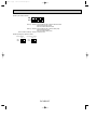
9
OPERATION FLOW-CHART
MAIN OPERATION
START
Power circuit
breaker
1
NO
YES
YES
Check SW
ON twice
NO
Operation SW
ON
w 1
YES
NO
“OFF” timer
YES
NO
NO
Set time
complete
“ON” timer
YES
YES
Set time
complete
NO
YES
w 2
NO
Trouble
NO
YES
STOP
Trouble STOP
PROTECTION DEVICE
SELF HOLD RELEASE
PROTECTION DEVICE
SELF HOLD
w 3
Remote controller
trouble display
Remote controller
indicator lamp OFF
Remote controller
operation display
Operating mode
(COOL)
NO
Operating mode
(DRY)
YES
COOL operation
YES
DRY operation
w 5
FAN operation
Indoor side
Fan STOP
Outdoor side
w 4
Compressor OFF
Fan STOP
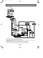
w1 In addition, the centralised control and remote control can be operated.
w2 The modes which indicate the sources of trouble are listed below.
● EO-Signal transmitting/receiving error
● P1-Room temperature thermistor malfunction
● P2-Indoor coil thermistor malfunction
● P4-Drain sensor malfunction
● P5-Drain overflow
● P6-Coil frost/overheat protection
● P7-System error
● P8-Outdoor unit trouble
w3 The CHECK switch will show if an error has occurred in the past.
w4 The 3-minute time-delay functions after compressor stops.
w5 In FAN mode, fan speed and vane operation depend on the remote controller setting. (Compressor is OFF.)
OC185A-16
OC185A--1.qxp 1.12.19 10:23 AM Page 17
COOLING OPERATION
COOL operation
NO
Initial
COOLING
YES
w8
Vane initial
setting
Vane
55 deg downward angle
70 deg downward angle
NO
YES
Fan speed
LOW
NO
YES
NO
Vane setting notch
Downward discharge
1 hour
YES
Vane horizontal
airflow
w9
Compressor
YES
thermostat
ON
NO
Allowance
cancel
NO YES
3-minute
time delay
YES
NO
6-minute
time delay
NO
3-minute
compressor operation
Allowance
period
NO
6 minute
time delay
NO
YES
Coil frost protection
Allowance set
YES
Coil frost
protection
w 10
YES
NO
w 11
NO
Cooling area
NO
YES
10-minute
compressor operation
Indoor coil
temperature is
50˚F or higher
YES
YES
Allowance cancel
Coil frost
prevention
YES
Defrosting protection
detection temperature
30˚F or lower
NO
NO
Compressor ON
NO
1 min continue
YES
NO
6-minute
time delay
FAN speed
LOW
FAN speed
LOW 5 min
elapse
NO
YES
16-minute
compressor operation
YES
Indoor pipe
temperature is
34˚F or lower
NO
NO
3-minute
time delay
YES
Outdoor unit
trouble
YES
Coil frost
prevention
Coil frost
prevention release
Compressor OFF
1
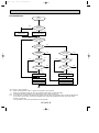
w8 When operation stops or changes to cooling or dry mode, the auto vane turns to a horizontal angle. If operation changes
during auto vane SWING, the auto vane will continue to swing.
w9 When operating TEST RUN, the thermostat will be continuously ON.
w10After 3 minute compressor operation, if the indoor coil thermistor reads 5°F or below for 3 minutes, the compressor will
stop for 6 minutes.
w11Heating area : Indoor coil temperature is more than 9 degrees above the room temperature.
Cooling area : Indoor coil temperature is more than 9 degrees below the room temperature.
FAN area : Indoor coil temperature is within 9 degrees either way of the room temperature.
OC185A-17
OC185A--1.qxp 1.12.19 10:23 AM Page 18
DRY OPERATION
DRY
operation
NO
Initial dry
operation
w8
YES
Vane
setting notch
Vane initial setting
YES
w12
Room temperature is
64°F or lower
NO
NO
During
compressor ON
YES
3-minute
compressor
operation
NO
NO
YES
NO
YES
3-minute
time delay
w9
Compressor &
thermostat ON
YES
Compressor &
thermostat
ON
w9
NO
YES
NO
Compressor ON
time completes
10-minute
compressor
OFF
NO
YES
YES
w13
10-minute compressor
OFF timer start
Compressor ON
time set
Compressor OFF
Compressor ON
w14
Fan STOP
w14
Fan speed LOW
1
w8—9 Refer to page OC185A-17.
w12
When room temperature is 64°F or below, the compressor cannot operate.
When room temperature rises over 64°F the compressor starts after a 3-minute time delay.
w13
Compressor ON time is decided by room temperature. Refer to page OC185A-22.
w14
In dry operation, compressor ON makes the fan speed LOW. Also, when the compressor OFF and the pipe temperature
is 79°F or less, the fan stops, or when the compressor OFF and the pipe temperature is below 43°F the fan speed
changes to LOW mode.
It is not possible to set the fan speed with the remote controller
OC185A-18
OC185A--1.qxp 1.12.19 10:23 AM Page 19
10
MICROPROCESSOR CONTROL
1. OUTLINE OF MICROPROCESSOR CONTROL
REMOTE CONTROLLER
INPUT to remote controller
● Processes and transmits orders.
OUTPUT to remote controller
● Indication LCD lights.
● OFF-ON switching.
● COOL • DRY • FAN selector switching.
● HIGH-LOW fan speed switching.
● TIMER mode selector-switching
● Timer setting.
● Self diagnostic troubleshooting.
● TEST RUN switching.
● CHECK mode switching.
● AUTO Vane setting.
SET TEMP
COOL
DRY
˚F
FAN
SWING
AM
PM
FAN
ON
OFF
AM
PM
NOT AVAILABLE
POWER ON / OFF
Indoor unit
TEMP
INPUT from indoor unit
INDOOR CONTROLLER BOARD
● Room temperature thermistor.
● Indoor coil thermistor.
● Receives orders from remote controller and temperature
data from indoor unit.
● Processes orders and data.
● Controls indoor and outdoor operation.
● Self diagnostic function
w System control operation.<Optional>
w Emergency operation
OUTPUT to indoor unit
● Fan: ON-OFF.
● Fan speed: HIGH-LOW.
● AUTO vane’s angle setting.
● Emergency stop.
Polar, two (2) - core cable
INPUT from outdoor unit
● Compressor protection device working.
12VDC
Independent Control of
Outdoor Unit
OUTDOOR CONTROLLER
BOARD
● Receives orders from
indoor controller.
● Emergency stop.
OUTPUT to outdoor unit
● Compressor motor and outdoor fan motor : ON-OFF.
OC185A-19
Outdoor unit
OC185A--1.qxp 1.12.19 10:23 AM Page 20
2. INDOOR UNIT CONTROL
2-1COOL operation
<How to operate>
1 Press POWER ON/OFF button.
2 Press MODE button to set operation mode to COOL.
3 Set desired temperature with
or
button.
NOTE: 1. Set temperature changes by 2 °F in the range 65~87 °F
each TEMP
or
button is pressed.
2. Set temperature is displayed on the LCD.
SET TEMP
COOL
DRY
˚F
FAN
SWING
AM
PM
FAN
ON
OFF
AM
PM
NOT AVAILABLE
POWER ON / OFF
TEMP
<COOL operation time chart>
Operation starts by
POWER button
ON.
Room temperature
becomes equal to
set temperature.
Room temperature
rises above set
temperature.
Operation stops by
POWER button
OFF.
ON
Thermostat
OFF
LOW or HIGH
ON
Indoor fan
LOW or HIGH
OFF
Depends on remote controller setting
ON
Auto vane
OFF
Compressor
OFF
CLOSE
CLOSE
ON
Minimum 3 minutes
w1
w1 Even if the room temperature rise above the set temperature during this period, the compressor will not start until this period has ended.
(1) Compressor control
1 3-minute time delay
To prevent overload, the compressor will not start within 3 minutes after stop.
2 The compressor runs when room temperature is higher than set temperature.
The compressor stops when room temperature is equal to or lower than the set temperature.
The compressor maintains the previous state when the room temperature minus the set temperature is 0 degrees or more,
or lower than 2 degrees.
3 The compressor stops in check mode or during protective functions.
4 Coil frost prevention
To prevent indoor coil frost, the compressor will stop when the indoor coil thermistor (RT2) reads 34°F or below after the
compressor has been continuously operated for at least 16 minutes or more. When the indoor coil temperature rises to
50°F or above, the compressor will start in a 3-minute(w2) time delay.
w2 When the indoor coil temperature is 30°F or less, the compressor starts in 6 minutes.
NOTE : By cutting the jumper wire JR2 on indoor controller board, the start temperature of coil frost prevention changes from
34°F to 36°F.
OC185A-20
OC185A--1.qxp 1.12.19 10:23 AM Page 21
5 Coil freeze protection
When the indoor coil temperature becomes - 5°F or below, coil freeze protection will proceed as follows.
<Start condition>
After the compressor has been continuously operated for 3 minutes or more, and the indoor coil temperature has been
- 5°F or below for 3 minutes, the coil frost protection will start.
<Coil frost protection>
Compressor stops for 6 minutes, and then restarts.
If the start condition is satisfied again during the first 10 minutes of compressor operation, both the indoor and outdoor units
stop, and the remote controller displays this occurrence.
<Termination conditions>
Coil frost protection released when the start condition is not satisfied again during the allowance, or when the COOL mode
stops changes another mode.
(2)Indoor fan control
Indoor fan speed depends on the remote controller setting.
However, if an outdoor unit abnormality is detected, the indoor fan speed will be LOW, regardless of the remote controller
setting.
(3)Auto vane control
Auto vane position depends on the remote controller setting.
(4)Detecting abnormalities in the outdoor unit
After the compressor has been continuously operated for 3 minutes, if the difference between the indoor coil temperature
and the room temperature is out of RANGE C for 1 minute, the indoor fan speed will turn to LOW. Five minutes later, if the
difference is still out of RANGE C, the outdoor unit is functioning abnormally. Thus, the compressor will stop and the remote
controller will display this occurrence.
RANGE A : Indoor coil temperature is more than 9 degrees above room temperature.
RANGE B : Indoor coil temperature is within 9 degrees either way of room temperature.
RANGE C : Indoor coil temperature is more than 9 degrees below room temperature.
(5)AUTO VANE CONTROL
1 Frequency judgement
When the unit operates for the first time after the circuit breaker turned to ON, the frequency, 60Hz, is judged by the horizontally sensing switch. If The frequency cannot be judged immediately for some reason, the sensing operation continues
for 3 minutes with the vane motor at ON.
If the frequency cannot be judged yet after 3-minute sensing, the vane motor turns to OFF. But the AIR DISCHARGE
DIRECTION display continues to be indicated.
2 During cooling operation
When the cooling operation starts, the vane is automatically set to the horizontal However, the desired direction among four
below-listed can be selected with the vane button on the remote controller.
a) 10°
b) 30° downward
10°
c) 60° downward
d) 70° downward
e) Automatic swing
30°
NOTE : 30° is available only when the fan speed is HIGH.
<AUTO RETURN>
When discharge 60° or 70° continues for 1 hour with the fan speed at LOW, the
discharge direction turns to the horizontal discharge automatically.
NOTE1 : After that, 60° or 70° is available by setting with the remote controller, and
it continues for 1 hour.
NOTE2 : If the discharge direction changes from 60° or 70° , the direction returns
to the horizontal discharge when 1 hour has passed since the discharge 60° started.
NOTE3 : If the discharge direction changes from 60° (or 70° ) to the horizontal discharge,
the 1-hour timer to return the horizontal discharge is cancelled.
3 During the operation OFF, the auto vane is in the airflow shut-off position.
4 When the vane motor is out of order or the connector is badly connected, the
remote controller display of the remote controller does not change.
OC185A-21
60°
70°
Automatic
swing
OC185A--1.qxp 1.12.19 10:23 AM Page 22
2-2 DRY operation
<How to operate>
1 Press POWER ON/OFF button.
2 Press MODE button to set operation mode to DRY.
3 Set desired temperature with
or
button.
NOTE: 1. Set temperature changes by 2 °F in the range 65~87 °F
each TEMP
or
button is pressed.
2. Set temperature is displayed on the LCD.
SET TEMP
COOL
DRY
˚F
FAN
SWING
AM
PM
FAN
ON
OFF
AM
PM
NOT AVAILABLE
POWER ON / OFF
TEMP
Operation starts by
POWER button
ON.
Room temperature
becomes equal to
set temperature.
Room temperature
rises above set
temperature.
Operation stops by
POWER button
OFF.
ON
Thermostat
OFF
LOW speed
ON
Indoor fan
LOW speed
OFF
Depends on remote controller setting
ON
Auto vane
OFF
Compressor
OFF
CLOSE
CLOSE
ON
MIN. 3 minutes w2
w2 Even if the room temperature rises above the set temperature during this period, the compressor will not start until this period has ended.
(1)Compressor control
1 3-minute time delay
To prevent overload, the compressor will not start within 3 minutes after stop.
2 The compressor runs when the room temperature is higher than the set temperature.
The compressor stops when the room temperature is equal to or lower than the set temperature.
3 The compressor stops in check mode or during protective functions.
4 The compressor will not start when the room temperature is below 63 °F. The compressor starts intermittent operation when
the power is turned ON with room temperature above 63 °F. The compressor ON/OFF time depends on the thermostat
ON/OFF and the room temperature as follows.
After 3-minute compressor operation,
● If the room temperature thermistor reads above 83 °F with thermostat ON, the compressor will operate for 6 more minutes and then stop for 3 minutes.
● If the room temperature thermistor reads 79 °F to 83 °F with thermostat 0N, the compressor will operate for 4 more minutes and then stop for 3 minutes.
● If the room temperature thermistor reads 75 °F to 79 °F with thermostat ON, the compressor will operate for 2 more minutes and then stop for 3 minutes.
● If the room temperature thermistor reads below 75 °F with thermostat ON, the compressor will stop for 3 minutes.
● If the thermostat is OFF, regardless of room temperature, the compressor will stop for 10 minutes.
5 Coil frost protection
Coil frost protection in DRY operation is the same as in COOL operation.
6 Coil freeze prevention
Coil freeze prevention does not operate in DRY operation.
OC185A-22
OC185A--1.qxp 1.12.19 10:23 AM Page 23
(2) Indoor fan control
The indoor fan runs on LOW speed during compressor operation. The fan speed cannot be changed with the remote controller.
Also, the indoor fan does not run during compressor OFF.
(3)Auto vane control
Same as in COOL operation.
(4)Detecting abnormalities in the outdoor unit
An abnormality in the outdoor unit can not be detected in DRY operation.
2-3 FAN operation
<How to operate>
1 Press POWER ON/OFF button.
2 Press MODE button to set operation mode to Fan.
(1) Indoor fan control
The indoor fan speed depends on the remote controller setting.
(2) Auto vane control
The auto vane position depends on the remote controller setting.
SET TEMP
COOL
DRY
˚F
FAN
SWING
AM
PM
FAN
OFF
ON
AM
PM
NOT AVAILABLE
POWER ON / OFF
TEMP
2-4 TIMER operation
SET TEMP
COOL
DRY
˚F
FAN
SWING
AM
PM
FAN
ON
<How to operate>
1 Push POWER ON/OFF button.
2 Check if or not the current time is correct.
3 Push the STOP or START button and select the desired time.
4 Set the timer time using HR and MIN buttons.
OFF
AM
PM
NOT AVAILABLE
POWER ON / OFF
MODE
FAN
CLOCK
TIMER SET
VANE
STOP
START
HR
MIN.
OC185A-23
OC185A--1.qxp 1.12.19 10:23 AM Page 24
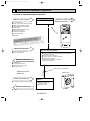
2-5 Test run
(1) Turn on the main power of unit.
(2) Turn the adjusting switch on the back of the
wireless remote controller to “SET”
CHECK and TEST RUN will
start flashing.
SET TEMP
COOL
Wireless remote controller with backside battery cover
removed Display will start finishing.
DRY
˚F
FAN
SWING
AM
PM
FAN
ON
OFF
AM
PM
★(3) Push the MIN button TEST RUN and
the operating mode will be displayed (Refer
to the illustrated sample display at left)
Turn the adjusting switch to "SET"
Display will start flashing
NOT AVAILABLE
POWER ON / OFF
★(4) Push the MODE button, change the
mode to “FAN” and make sure that there
will be blowout of air.
Reset
After refiling batteries.
Press the reset button.
COOL
DRY
FAN
FAN
TIMER SET
VANE
STOP
START
HR
MIN.
★(5) Push the MODE button, change the mode to
COOL and make sure that there will be
blowout of cool air.
45
23
901
Nrm Set
CLOCK
8
67
MODE
ON / OFF
★(6) Push the FAN button and make sure that
★ For operations marked , point the transmitter to the wireless
receiver, and make sure that you will hear a short beep
from the receiver.
there will be HIGH (or LOW) discharge of air.
★(7) Push the VANE button and make sure the
operation of the auto vane.
★(8) Push the POWER ON/OFF button and cancel
the test run.
(9) After completing a test run, be sure to turn the
adjusting switch back to “Nrm”.
● The test run automatically stops in 2 hours.
● Set temperature is not displayed during test run.
2-6 Emergency operation
When the remote controller or microprocessor malfunctions and no other trouble exists, emergency operation is available
by setting the dip switch on the controller board.
[Check items]
(1) Make sure the compressor and the fans are running normally.
(2) Locate the trouble with the self-diagnostic function. If the selfdiagnostic function indicates that the protection device (such
as coil frost protection) is functioning, the sources must be
removed before attempting emergency operation.
Emergency operation ON/OFF is activated not with the remote
controller but with the circuit breaker.
[Emergency operation procedure]
(1)Cooling operation is available by setting the dip switch SW3
1and 2 ON and 3 OFF on the indoor controller board.
(2)To start emergency operation, turn the outdoor side circuit
breaker ON first, and then the indoor side circuit breaker ON.
(3)During emergency operation, the indoor fan runs on HIGH
speed, the compressor runs continuously, and the louver stops.
(4)Thermostat will not function.
(5)Do not use emergency cooling operation for more than 10 hours,
as the indoor coil may freeze.
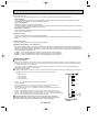
INDOOR CONTROLLER BOARD
SW3
ON
OFF
OC185A-24
1 2 3
COOLING
OC185A--1.qxp 1.12.19 10:23 AM Page 25
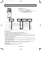
2-7 Wireless remote controller pair number setting operation
Switches are located on the indoor unit PC board and inside the remote
controller as shown.
• Setting the SW1 (PC board inside indoor unit)
Sub-switches 7 or 8 of SW1 can be used as follows to assign a pair No.
Pair Number
SW1
0
ON
OFF
1
ON
OFF
12 34 5 6 78
12 34 5 6 78
Pair Number
SW1
2
ON
OFF
3
ON
OFF
12 34 5 6 78
12 34 5 6 78
• The pair No. SW of the remote controller has been set to ‹‹0›› at the time of
shipment.
Reset
After refiling batteries.
Press the reset button.
901
45
23
8
67
Nrm Set
A
Note:
Make sure that a pair number of the remote controller (shown an A)
agrees with that of the indoor unit PC board.
This is because wireless signals of indoor units are distinguished
from one another when several indoor units are installed in the same
room.
OC185A-25
OC185A--1.qxp 1.12.19 10:23 AM Page 26
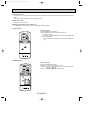
2-8 Function of jumper wire and dip switch on indoor controller board
1. Jumper wire
JR
1
2
3
4
5
6
1 JR1:Jumper wire for the auto vanes.
Cut JR1 for the unit WITHOUT auto vanes.
2 JR2:Jumper wire for the temperature to start coil frost prevention.
Cutting JR2 changes the temperature from 34°F to 36°F.
3 JR3:Not for use.
4 JR4:Not for use.
5 JR5:Jumper wire for detecting abnormalities in the outdoor unit.
Cutting JR5 makes this detection unavailable. (Occurrence of abnormality can not be detected.)
6 JR6:Jumper wire for auto restart function.
Cutting JR6 makes the auto restart function available.
2.Dip switch
1 SW1 (Function selector switch)
ON
OFF
1 2 3 4 5 6 7 8
SW1-1) Switch for power supply
Not for use.(Only 115V)
SW1-2) Not for use.
SW1-3) Not for use.
SW1-4 ~ SW1-6) Switch for capacity of each model
PK18FL, PK18FL1 PK24FL, PK24FL1 PK30FL, PK30FL1 PK36FL, PK36FL1
ON
OFF
ON
OFF
4 5 6
ON
OFF
4 5 6
ON
OFF
4 5 6
4 5 6
SW1-7 ~ SW1-8) Switch for the pair number of wireless remote controller
1
0
ON
OFF
ON
OFF
7 8
2
ON
OFF
7 8
3
ON
OFF
7 8
OC185A-26
7 8
OC185A--1.qxp 1.12.19 10:23 AM Page 27
2 SW2 (Unit selector switch)
ON
OFF
1 2 3 4 5
SW2-1) Switch for air conditioner with or without electric heater
ON:Unit with electric heater
OFF:Unit without electric heater
SW2-2) Switch for air conditioner with or without heat pump
ON:Unit with heat pump
OFF:Unit without heat pump
SW2-3, SW2-4, SW2-5) Switch for function code
3 SW3 (Emergency operation switch)
Normal operation
For emergency cooling
1 2 3
ON
OFF
1 2 3
ON
OFF
OC185A-27
OC185A--1.qxp 1.12.19 10:23 AM Page 28
11
TROUBLESHOOTING
1. Self-diagnostic function
(1) Turn on the main power of the unit.
(2) Turn the adjusting switch on the back of the wireless remote controller to “SET” CHECK TEST RUN TEST RUN will start flashing.
★(3) Push the HR button CHECK will start flashing.
★(4) While pointing the transmitter to the receiver, push the HR button. At this point, you will hear an intermittent buzzer sound, and
operating flash will show check codes.
Intermittent buzzer sound
Operating lamp flashing time
SET TEMP
COOL
DRY
˚F
FAN
SWING
AM
PM
FAN
Buzzer sound
ON
OFF
AM
PM
NOT AVAILABLE
1 second (0.5 second interval)
Repeats as often as the number of the check code
Beep
POWER ON / OFF
MODE
Check code
Nature of irregularity
1
Irregular intake sensor
2
Irregular piping sensor
4
Irregular drain sensor
5
Irregular drain pump
6
Freezing protected
8
Irregular outdoor unit
9
NO irregular
FAN
CLOCK
TIMER SET
VANE
STOP
START
HR
MIN.
★(5) Push the POWER ON/OFF button and cancel the test run.
(6) After completing a test run, be sure to turn the adjusting switch
back to “Nrm”.
Wireless remote controller with backside battery cover removed Display will start flashing.
For operations marked*, point the transmitter to the wireless receiver, and make sure that you will hear a short beep from the
receiver.
Turn the adjusting switch to "Set"
Display will start flashing
Reset
After refiling batteries.
Press the reset button.
COOL
DRY
FAN
901
45
23
8
67
Nrm Set
POWER ON / OFF
OC185A-28
OC185A--1.qxp 1.12.19 10:23 AM Page 29
2. OTHER TROUBLES AND CAUSES
Auto vanes do not work.
Unit stops after 5 to
20 seconds operation
Power ON/OFF button
is not available.
Auto vane motor is damaged.
Auto vane motor does not work.
Auto vane motor relay is damaged.
Connector is poorly connected.
Auto vane motor is poorly assembled.
Indoor controller board is damaged.
Protection function is working.
Refer to check code on remote controller display.
Indoor/outdoor connecting wire is connected
incorrectly.
Indoor/outdoor connecting wire shorts.
Compressor protector is damaged.
Defroster is broken.
Remote controller is damaged.
Transmission wire is poorly connected
Check
Diagnosis of malfunction
Cause
code
Abnormality of room temper- 1) Bad contact of thermistor
1
ature thermistor (RT1)
2) Damaged thermistor
Transmission wire is damaged.
Connector is poorly connected.
Check points
1) Check the thermistor.
2) Measure the resistance of the thermistor.
Normal resistance should be as follows.
32°F····15kΩ
86°F·····4.3kΩ
50°F······9.6kΩ 104°F·····3.0kΩ
68°F······6.3kΩ
If the resistance is normal, replace the indoor
controller board.
2
Abnormality of indoor coil
thermistor (RT2)
4
Abnormality of drain sensor
1) Bad contact of transmission
wire
2) Damaged thermistor
1) Check the connector.
2) Measure the resistance of the thermistor
(between ➃ - ➄of CN50).
As for the normal resistance, refer to the case
of 1.
If the resistance is normal, replace the indoor controller board.
5
Malfunction of drain pump
1) Malfunction of drain pump
2) Damaged drain sensor
1) Check the drain pump.
2) Check the drain sensor.
Check the drain sensor heater. Normal resis
tance should be 82Ω. (between 1 - 3of CN50).
If the resistance is normal, replace the indoor controller board.
6
Coil frost protection is working.
1) Short cycle of air cycle
2) Dirty air filter
3) Damaged fan
4) Abnormal refrigerant
1)
2)
3)
4)
Clear obstructions from the air cycle.
Clean the air filter
Check the fan.
Check the refrigerant temperature.
8
Abnormality in outdoor unit
1) Wrong wiring of indoor/outdoor
connecting wire
2) Reversed phase
3) Protection device is working
4) Damaged outdoor coil thermistor
1)
2)
3)
4)
Check the indoor/outdoor connecting wire.
Change the connection of electric wiring.
Check the protection device.
Measure the resistance of the outdoor coil thermistor. If the resistance is normal, replace the
outdoor controller board.
❈ The number of check code shows times of Buzzer sound.
OC185A-29
OC185A--1.qxp 1.12.19 10:23 AM Page 30
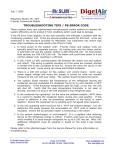
3. WRONG WIRING ON SITE
Symptom due to wrong wiring between indoor and outdoor units
Wrong wiring
Indoor unit
1
Thermostat
Outdoor unit
1
2
Phenomena
OFF
The outdoor unit stops.
ON
Operation stops. 9 minutes later, the check code ¨P8¨ appears
on the remote controller display.
OFF
Operation stops.
ON
9 minutes later, the check code ¨P8¨ appears on the remote controller display.
2
Disconnect between 1 and 1 or 2 and
2.
4. HOW TO CHECK THE PARTS
Parts name
Check points
Room temperature
thermistor
(RT1)
Pipe temperature
thermistor
(RT2)
Disconnect the connector, then measure the resistance using a tester.
(Surrounding temperature 50°F to 86°F)
Fan motor
Measure the resistance between the terminals using a tester.
Relay connector
1
Red
1
3 White
5
3
Black
5
Normal
Motor terminal
or
PK
Abnormal
Relay connector 18/24FL, 18/24FL1 30/36FL, 30/36FL1
Red-White
99.5'i10%
62.6'i10%
Open or short
White-Black
74.0'i10%
103.5'i10%
Measure the resistance between the terminals using a tester.
(Surrounding temperature 68°F to 86°F)
Vane motor
Orange
Red
M
Blue
Brown
Yellow
Pink
Connector
Abnormal
Open or short
Opening and closing temperature of protector
Open: 266i41°F(Fan motor OFF)
Close: 176i68°F(Fan motor ON)
Protector
4
5
2
Normal
4.3k' to 9.6k'
3 6 1
Brown-Yellow
Brown-Blue
Red-Orange
Red-Pink
Normal
Abnormal
186 to 214'
Open or short
OC185A-30
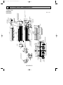
OC185A--2.qxp 1.12.19 10:18 AM Page 31
12
DISASSEMBLY PROCEDURE
Indoor unit PK24FL, PK24FL1
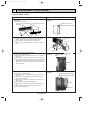
OPERATING PROCEDURE
1. Removing the lower side of the indoor unit from the installation plate
(1) Remove the 2 screws.
Hang the indoor unit hangers to the catches on the installation plate.
PHOTOS&ILLUSTRATION
Figure 1
Hanger of indoor unit
Catch of installation plate
Metal fixture
Screws
2. Removing the right side panel
(1) Remove the 2 screws of the right side panel:one on the
bottom and the other on the upper right-hand side.
(2) Disconnect the connector from the adapter case.
(3) Sliding the right side panel to the right, pull it out toward
you.
Figure 2
Connector
Indoor controller
board
Right side panel
Terminal cover
Connector
Electrical box cover
3. Removing the indoor controller board
(1) Remove the right side panel.
(2) Remove the screw of the electrical box cover, and remove
the cover.
(3) Disconnect the connectors on the indoor controller board.
(4) To unhook the catches on the right-hand side of the indoor
controller board, pull the left-hand side toward you and lift
up the cover to the right. Then the indoor controller board
can be removed.
4. Removing the electrical box
(1) Remove the right side panel.
(2) Remove the screw of the electrical box cover, and remove
the cover.
(3) Remove the room temperature thermistor and the pipe
temperature thermistor.
(4) Disconnect the vane motor connector on the indoor controller board.
(5) Remove the 2 screws of the electrical box.
(6) Disconnect the connector of the heater lead wire connector.
(7) Disconnect the connector of the fan motor lead wire.
(8) Remove the electrical box.
OC185A-31
Photo 1
Indoor controller
board
Electrical box
cover
Catches
Photo 2
Room temperature thermistor
Pipe temperature thermistor
Screws
Electrical box
OC185A--2.qxp 1.12.19 10:18 AM Page 32
OPERATING PROCEDURE
PHOTOS&ILLUSTRATION
(8) Remove the screws of the indoor controller board case,
and pull out the indoor controller board case.
Then the transformer and the capacitor and relay can be
serviced.
Photo 3
RELAY
Transformer
Capacitor
Indoor controller
board case
5. Removing the vane motor
(1) Remove the right side panel.
(2) Remove the screw of the electrical box cover, and remove
the cover.
(3) Remove the 2 screws of the vane motor, and remove the
motor from the shaft.
(4) Disconnect the vane motor connector on the indoor controller board.
Photo 4
Electrical parts box
Screws
Vane motor
Indoor controller board
6 Removing the intake grilles
(1) Remove the right side panel.
(2) To remove the left side panel, remove the screw on the
bottom and the screw on the upper left-hand side. (See
Figure 3.)
1. Press up this side of the left side panel to unhook the
catch on the panel from the catch on the unit.
2. Slide the left side panel to the left to remove the panel.
Note: Fix the unit to the metal fixture securely
(3) Remove the air filters.
(4) Hold and press the center cover to remove.
(5) Remove the screws of the grilles.
(6) Pull the lower side of the grille toward you and slide the
upper to the right to remove the grilles.
Figure 3
Catch on the left side panel
Catch on
the unit
Photo 5
Left side panel
Slide to the
right
Grilles
Screws for grilles
7. Removing the drain pan
(1) Remove the left and right side panels.
(2) Remove the grilles.
(3) Remove the electrical box cover.
(4) Loosen the drain hose band to remove.
(5) Remove the 3 screws of the drain pan, and slide the drain
pan toward you to remove.
Photo 6
Drain pan
Drain hose
band
Screws
Drain hose
OC185A-32
OC185A--2.qxp 1.12.19 10:19 AM Page 33
OPERATING PROCEDURE
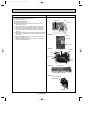
8. Removing the line flow fan and the fan motor
(1) Remove the left and right side panels.
(2) Remove the grilles.
(3) Remove the electrical box.
(4) Remove the drain pan.
(5) Loosen the screw that fixes the line flow fan to the fan
motor. (See Photo 7. )
(6) Remove the 4 screws of the motor fixture, and remove the
fan motor and the motor fixture at a time (See Photo 8.)
(7) Remove the screws of the left and right motor supports,
and remove the motor supports and the fan motor. (See
Photo 9.)
(8) Remove the 2 screws on the left and right sides of the heat
exchanger, and pull the bearing support toward you. (See
Photo 11.)
(9) Remove the screw of the center support, and remove the
support. (See Photo 10. )
(10) Pull the left-hand side of the heat exchanger toward you,
and remove the line flow fan.
PHOTOS
Photo 7
Screw
Line flow fan
Fan motor
Photo 8
Screws
Fan motor
Motor fixture
Photo 9
Fan motor
Screw
Screw
Motor support
Motor
support
Photo 10
Line flow fan
Center support
Screw
Photo 11
Heat exchanger
Bearing support
Line flow fan
OC185A-33
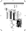
OC185A--2.qxp 1.12.19 10:19 AM Page 34
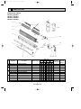
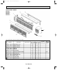
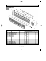
13
PARTS LIST
ELECTRICAL PARTS
PK18FL, PK18FL1
PK24FL, PK24FL1
PK30FL, PK30FL1
PK36FL, PK36FL1
23
1
2
24
3
26
22
25
4
5
20
21
19
6
7
18
13
14
11 12
8
9
10
15
16
Q'ty / set
Wiring
Remarks
Diagram
(Drawing No.)
Symbol
FL FL1 FL FL1 FL FL1 FL FL1
PK18 PK24 PK30 PK36
No.
Parts No.
1
R01 005 103
SLEEVE BEARING
1
1
1
1 1
1
1 1
2
R01 Z61 102
BEARING MOUNT
1
1
1
1 1
1
1 1
R01 13G 114
LINE FLOW FAN (L)
1
1
1
1
R01 17G 114
LINE FLOW FAN (L)
1
1
1 1
T7W B04 480
HEAT EXCHANGER
T7W B06 480
HEAT EXCHANGER
T7W B05 480
HEAT EXCHANGER
1
1
1 1
T7W B04 529
DRAIN PAN ASSY
T7W E13 529
DRAIN PAN ASSY
T7W B05 529
DRAIN PAN ASSY
T7W E14 529
DRAIN PAN ASSY
3
4
5
Parts Name
Specifications
17
1
1
1
1
1
1
1
1
1
1
1
OC185A-34
1
OC185A--2.qxp 1.12.19 10:19 AM Page 35
Q'ty / set
No.
Parts No.
Parts Name
Specifications
Wiring
Remarks
Diagram
(Drawing No.)
Symbol
FL FL1 FL FL1 FL FL1 FL FL1
PK18 PK24 PK30 PK36
6
R01 12G 063 JOINT SHAFT
1 1
1 1
1 1
1 1
7
R01 12G 621 CENTER COVER
1 1
1 1
1 1
1 1
R01 12G 002 AUTO VANE W
2 2
2 2
2 2
2 2
1 1
1 1
1 1
1 1
10 R01 12G 223 VANE MOTOR
1 1
1 1
1 1
1 1
MV
11 R01 87Y 202 ROOM TEMPERATURE THERMISTOR
1 1
1 1
1 1
1 1
RT1
12 R01 22A 202 PIPIE TEMPERATURE THERMISTOR
1 1
1 1
1 1
1 1
RT2
8
R01 16G 002 AUTO VANE W
9
R01 KV5 527 DRAIN HOSE
13 R01 556 246 TERMINAL BLOCK
2P(1,2)
1 1
1 1
1 1
1 1
TB4
14 T7W 410 716 TERMINAL BLOCK
3P(L1,N,GR)
1 1
1 1
1 1
1 1
TB2
15 T7W B02 255 FAN MOTOR CAPACITOR
8µF 440V
1 1
1 1
1 1
1 1
C
1 1
1 1
1 1
1 1
I.B
2 2
2 2
2 2
2 2
F1.2<I.B>
1 1
1 1
1 1
1 1
T
2 2
2 2
2 2
2 2
1 1
1 1
16 T7W E03 310 INDOOR CONTROLLER BOARD
17 T7W 410 239 FUSE
250V 6A
18 T7W E01 799 TRANSFORMER
19
R01 12G 105 RUBBER MOUNT
R01 16G 105 RUBBER MOUNT
20
R01 13G 115 LINE FLOW FAN (R)
1 1
1 1
R01 17G 115 LINE FLOW FAN (R)
21
T7W B02 762 FAN MOTOR
PN4W40-K
T7W B03 762 FAN MOTOR
PN4W70-K
1 1
MF
1 1
1 1
1 1
22 R01 18G 075 WIRELESS REMOTE CONTROLLER HOLDER
1 1
1 1
1 1
1 1
23 T7W E01 714 WIRELESS REMOTE CONTROLLER
1 1
1 1
1 1
1 1
24 T7W 71J 675 FAN GUARD
2 2
2 2
2 2
2 2
25 R01 12G 103 SLEEVE BEARING
1 1
1 1
1 1
1 1
26 R01 KV5 102 BEARING MOUNT
1 1
1 1
1 1
1 1
OC185A-35
MF
W.R
OC185A--2.qxp 1.12.19 10:19 AM Page 36
STRUCTURAL PARTS
PK18FL
PK18FL1
PK24FL
1
PK24FL1
9
8
7
2
3
7
6
4
5
Part number that is circled is not shown in the figure.
Q'ty / set
No.
Parts No.
Parts Name
18FL 18FL1
1
2
3
R01 12G 662 SIDE PANEL (L) W
1
R01 12G 812 UNDER PLATE W
1
1
1
1
1
1
1
R01 E00 811 NOSE W
1
1
1
R01 E01 812 UNDER PLATE W
R01 12G 811 NOSE W
Wiring
Remarks
Diagram
(Drawing No.)
Symbol
24FL 24FL1
PK
Specifications
1
4
R01 A17 500 AIR FILTER W
4
4
4
4
5
T7W E01 317 WIRELESS ADAPTER BOARD
1
1
1
1
6
T7W E00 661 SIDE PANEL (R)
1
1
1
1
7
R01 12G 691 INTAKE GRILLE W
2
2
2
2
8
R01 12G 808 BACK PLATE
1
1
1
1
9
R01 E01 641 TOP PLATE W
1
1
1
1
1
1
1
1
10 R01 12G 523 DRAIN SOCKET
OC185A-36
W.B
OC185A--2.qxp 1.12.19 10:19 AM Page 37
STRUCTURAL PARTS
PK30FL
PK30FL1 1
PK36FL
PK36FL1
9
10
7
8
2
3
7
6
4
5
Part number that is circled is not shown in the figure.
Q'ty / set
No.
Parts No.
Parts Name
30FL 30FL1
1
2
3
Wiring
Remarks
Diagram
(Drawing No.)
Symbol
36FL 36FL1
PK
Specifications
R01 12G 662 SIDE PANEL (L) W
1
R01 16G 812 UNDER PLATE W
1
1
1
1
1
R01 E00 812 UNDER PLATE W
1
R01 16G 811 NOSE W
1
1
1
R01 E01 811 NOSE W
1
1
4
R01 A17 500 AIR FILTER W
5
5
5
5
5
T7W E01 317 WIRELESS ADAPTER BOARD
1
1
1
1
6
T7W E00 661 SIDE PANEL (R)
1
1
1
1
7
R01 12G 691 INTAKE GRILLE W
2
2
2
2
8
R01 16G 692 INTAKE GRILLE W
1
1
1
1
9
R01 16G 808 BACK PLATE
1
1
1
1
10 R01 E00 641 TOP PLATE W
1
1
1
1
11 R01 12G 523 DRAIN SOCKET
1
1
1
1
OC185A-37
W.B
3400 Lawrenceville Suwanee Road ● Suwanee, Georgia 30024
Toll Free: 800-433-4822 ● Toll Free Fax: 800-889-9904
www.mrslim.com
Specifications are subject to change without notice.