1
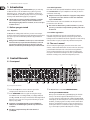
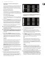
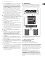
User Manual ULTRAGRAPH DIGITAL DEQ1024 Ultra-High Precision 24-Bit/96 kHz Equalizer, Feedback Destroyer and Dynamics Processor 2 ULTRAGRAPH DIGITAL DEQ1024 Table of Contents Thank you........................................................................ 2 Important Safety Instructions....................................... 3 Legal Disclaimer.............................................................. 3 Limited Warranty............................................................ 3 1. Introduction................................................................ 4 1.1 Before you get started....................................................... 4 1.1.1 Shipment........................................................................... 4 1.1.2 Initial operation.............................................................. 4 1.1.3 Online registration........................................................ 4 1.2 The user’s manual................................................................ 4 2. Control Elements........................................................ 4 2.1 Front panel............................................................................. 4 2.2 Rear panel.............................................................................. 6 3. Applications................................................................ 7 3.1 Master equalizer in sound reinforcement systems.............................................................. 7 3.2 Equalizer in the monitor path......................................... 8 3.2.1 Priming a monitor system.......................................... 8 3.3 Using the ULTRAGRAPH DIGITAL in the studio.................................................................................. 9 3.4 Special sound effects......................................................... 9 4. Installation.................................................................. 9 4.1 Rack mounting ..................................................................... 9 4.2 Audio connections.............................................................. 9 4.3 Digital connections (AES/EBU and S/PDIF).............. 10 5. Specifications............................................................ 10 Thank you Thank you very much for expressing your confidence in BEHRINGER products by purchasing the ULTRAGRAPH DIGITAL DEQ2496, an extremely high-quality digital equalizer with built-in 24-bit/96 kHz A/D and D/A converters, making it an ideal tool for both live and studio applications. 3 ULTRAGRAPH DIGITAL DEQ1024 Important Safety Instructions Terminals marked with this symbol carry electrical current of sufficient magnitude to constitute risk of electric shock. Use only high-quality professional speaker cables with ¼" TS or twist-locking plugs pre-installed. All other installation or modification should be performed only by qualified personnel. This symbol, wherever it appears, alerts you to the presence of uninsulated dangerous voltage inside the enclosure - voltage that may be sufficient to constitute a risk of shock. This symbol, wherever it appears, alerts you to important operating and maintenance instructions in the accompanying literature. Please read the manual. Caution To reduce the risk of electric shock, do not remove the top cover (or the rear section). No user serviceable parts inside. Refer servicing to qualified personnel. Caution To reduce the risk of fire or electric shock, do not expose this appliance to rain and moisture. The apparatus shall not be exposed to dripping or splashing liquids and no objects filled with liquids, such as vases, shall be placed on the apparatus. 9. Do not defeat the safety purpose of the polarized or grounding-type plug. A polarized plug has two blades with one wider than the other. A grounding-type plug has two blades and a third grounding prong. The wide blade or the third prong are provided for your safety. If the provided plug does not fit into your outlet, consult an electrician for replacement of the obsolete outlet. 10. Protect the power cord from being walked on or pinched particularly at plugs, convenience receptacles, and the point where they exit from the apparatus. 11. Use only attachments/accessories specified by the manufacturer. 12. Use only with the cart, stand, tripod, bracket, or table specified by the manufacturer, or sold with the apparatus. When a cart is used, use caution when moving the cart/apparatus combination to avoid injury from tip-over. 13. Unplug this apparatus during lightning storms or when unused for long periods of time. 14. Refer all servicing to qualified service personnel. Servicing is required when the apparatus has been damaged in any way, such as power supply cord or plug is damaged, liquid has been spilled or objects have fallen into the apparatus, the apparatus has been exposed to rain or moisture, does not operate normally, or has been dropped. 15. The apparatus shall be connected to a MAINS socket outlet with a protective earthing connection. 16. Where the MAINS plug or an appliance coupler is used as the disconnect device, the disconnect device shall remain readily operable. Caution These service instructions are for use by qualified service personnel only. To reduce the risk of electric shock do not perform any servicing other than that contained in the operation instructions. Repairs have to be performed by qualified service personnel. 1. Read these instructions. 2. Keep these instructions. 3. Heed all warnings. 4. Follow all instructions. 5. Do not use this apparatus near water. 6. Clean only with dry cloth. 7. Do not block any ventilation openings. Install in accordance with the manufacturer’s instructions. 8. Do not install near any heat sources such as radiators, heat registers, stoves, or other apparatus (including amplifiers) that produce heat. LEGAL DISCLAIMER TECHNICAL SPECIFICATIONS AND APPEARANCES ARE SUBJECT TO CHANGE WITHOUT NOTICE AND ACCURACY IS NOT GUARANTEED. BEHRINGER, KLARK TEKNIK, MIDAS, BUGERA, AND TURBOSOUND ARE PART OF THE MUSIC GROUP (MUSIC-GROUP.COM). ALL TRADEMARKS ARE THE PROPERTY OF THEIR RESPECTIVE OWNERS. MUSIC GROUP ACCEPTS NO LIABILITY FOR ANY LOSS WHICH MAY BE SUFFERED BY ANY PERSON WHO RELIES EITHER WHOLLY OR IN PART UPON ANY DESCRIPTION, PHOTOGRAPH OR STATEMENT CONTAINED HEREIN. COLORS AND SPECIFICATIONS MAY VARY FROM ACTUAL PRODUCT. MUSIC GROUP PRODUCTS ARE SOLD THROUGH AUTHORIZED FULLFILLERS AND RESELLERS ONLY. FULLFILLERS AND RESELLERS ARE NOT AGENTS OF MUSIC GROUP AND HAVE ABSOLUTELY NO AUTHORITY TO BIND MUSIC GROUP BY ANY EXPRESS OR IMPLIED UNDERTAKING OR REPRESENTATION. THIS MANUAL IS COPYRIGHTED. NO PART OF THIS MANUAL MAY BE REPRODUCED OR TRANSMITTED IN ANY FORM OR BY ANY MEANS, ELECTRONIC OR MECHANICAL, INCLUDING PHOTOCOPYING AND RECORDING OF ANY KIND, FOR ANY PURPOSE, WITHOUT THE EXPRESS WRITTEN PERMISSION OF MUSIC GROUP IP LTD. ALL RIGHTS RESERVED. © 2013 MUSIC Group IP Ltd. Trident Chambers, Wickhams Cay, P.O. Box 146, Road Town, Tortola, British Virgin Islands LIMITED WARRANTY For the applicable warranty terms and conditions and additional information regarding MUSIC Group’s Limited Warranty, please see complete details online at www.music-group.com/warranty. 4 ULTRAGRAPH DIGITAL DEQ1024 1. Introduction 1.1.2 Initial operation In addition to graphic EQing, the ULTRAGRAPH DIGITAL gives you a wide array of additional functions, such as feedback destroyer, pink noise generator, limiter/noise gate etc., leaving no wishes open. With these and many more features the DEQ1024 is an absolutely all-purpose device for your recording or mastering studio and will definitely upgrade your equipment. Please make sure the unit is provided with sufficient ventilation, and never place the ULTRAGRAPH DIGITAL on top of an amplifier or in the vicinity of a heater to avoid the risk of overheating. ◊ Faulty fuses must be replaced with fuses of appropriate rating without exception! The correct value of the fuses needed can be found in the chapter “SPECIFICATIONS”. ◊ The following user’s manual is intended to familiarize you with the unit’s control elements, so that you can master all the functions. After having thoroughly read the user’s manual, store it at a safe place for future reference. 1.1 Before you get started Power is delivered via the cable enclosed with the unit. All requiered safety precautions have been adhered to. ◊ Please make sure that the unit is grounded at all times. For your own protection, you should never tamper with the grounding of the cable or the unit itself. 1.1.1 Shipment The DEQ1024 was carefully packed at the factory to assure secure transport. Should the condition of the cardboard box suggest that damage may have taken place, please inspect the unit immediately and look for physical indications of damage. ◊ Damaged units should NEVER be sent directly to us. Please inform the dealer from whom you acquired the unit immediately as well as the transportation company from which you took delivery of the unit. Otherwise, all claims for replacement/repair may be rendered invalid. 1.1.3 Online registration Please take a few minutes and send us the completely filled out warranty card within 14 days of the date of purchase. You may also register online at behringer.com. The serial number needed for the registration is located at the top of the unit. Failure to register your product may void future warranty claims. 1.2 The user’s manual The user’s manual is designed to give you both an overview of the control elements, as well as detailed information on how to use them. In order to help you understand the links between the controls, we have arranged them in groups according to their function. If you need to know more about specific issues, please visit our website at behringer.com, where you’ll find additional information on mixing consoles, effects units and dynamic processors. 2. Control Elements 2.1 Front panel (1) (14) (2) (12) (3) (4) (5) (6) (7) (11) (8) (9) (13) (10) Fig. 2.1: Front panel control elements (1) Use the 45-mm EQ faders to increase or decrease any one of the 31 frequency bands. Each fader has its own red LED. (2) Use the FADER RANGE switches to regulate increasing/decreasing in three different levels: +12/-12 dB (green LED), +6/-6 dB (green LED) and 0/-24 dB (yellow LED). The last option is well suited for eliminating feedback frequencies, since you can select a very pronounced lowering of a specific frequency range (-24 dB). ◊ Each switch on your DEQ1024 (with the exception of CONFIG and CLOCK) has its own LED that lights up when the respective function is activated. ◊ All settings you implement always affect both channels of your DEQ1024. (3) The DEQ1024 features an automatic FEEDBACK DESTROYER. Activating the FEEDBACK DESTROYER: When you press the ON/OFF switch (yellow LED lights up), the feedback destroyer scans the audio signal for feedback frequencies. As soon as one or more frequencies show feedback, the red LED of the RESET (HOLD) switch lights up. The affected frequencies are then automatically lowered. In addition, your audio program is constantly scanned for new feedback frequencies, and feedback is destroyed as it comes up. This makes sense for microphones that are in constant motion during a stage performance (e. g. vocal microphones), where feedback may arrise constantly. 5 ULTRAGRAPH DIGITAL DEQ1024 Deactivating the search function (feedback suppression remains active): If you now press the ON/OFF switch for a second time, the feedback analysis stops. Those frequencies emitting feedback will continue being lowered (RESET (HOLD) LED is still on). This procedure is well suited for stationary microphones, such as drum microphones. To start the “hunt” for feedback again, hit the ON/OFF switch once again. Displaying the feedback frequencies: If you briefly (for approx. 2 seconds) depress the RESET (HOLD) switch, the feedback frequencies that the DEQ1024 was able to find will be indicated on the respective fader LEDs. If no feedback occurs, the LEDs will stop being lit up for roughly 2 seconds. Deactivating the FEEDBACK DESTROYER: If you hold the RESET (HOLD) switch depressed for a few seconds, the filter settings are reset (RESET (HOLD) LED dies out) and the FEEDBACK DESTROYER is deactivated. Fig. 2.2: Graphic equalizer without frequency response correction This occurrence can be corrected by means of a specially developed algorithm utilized in the ULTRAGRAPH DIGITAL DEQ1024. Simply press the TRUE CURVE switch (green switch LED lights up). (4) If you press the FB INDICATOR switch (green switch LED lights up), the FBQ feedback detection system is activated. The frequency (or the frequencies) that cause feedback are now shown in the form of a brightly shining fader LED. All other LEDs are dimmed. Simply lower somewhat the pertinent frequency range until feedback is no longer present and the LED dies out. By displaying the intensity of individual frequency ranges, the feedback recognition system also functions as an audio analyzer. ◊ Please keep in mind that the FB INDICATOR only shows the intensity of the individual frequency bands. Not every frequency that is present automatically causes feedback. ◊ FEEDBACK DESTROYER and FB INDICATOR function independently from one another and can be activated simultaneously. Please bear in mind: when in 96-kHz mode, FEEDBACK DESTROYER and FB INDICATOR are not available! (5) When you keep the PINK NOISE switch depressed for a few seconds, the internal pink noise generator of your DEQ1024 is activated (red switch LED lights up) and the volume level of the test signal is gradually increased as long as the switch remains depressed (the level is shown on LEVEL METER (13)). Briefly pressing the PINK NOISE switch once again deactivates the function. PINK NOISE Room resonance and the transmission characteristics of your P.A. system naturally lift certain frequencies while lowering others. Pink noise is a neutral signal that can be played back over the P.A. system in order to measure these room characteristics. One such measurement of the frequency response with a special measurement microphone (e. g. BEHRINGER ECM8000) coupled to a real-time analyzer (integrated in the BEHRINGER ULTRACURVE PRO DEQ2496) delivers the foundation for setting up the equalizer. Boosted frequencies can be lowered by means of your equalizer, while frequencies that are too weak can be boosted, and a nearly linear playback is achieved. ◊ Try to orient yourself on a frequency whose signal level lies in the 0 dB to -3 dB range in order to avoid overdriving the equipment connected (e. g. amp, crossover). (6) In the world of ordinary graphic equalizers, there is always a difference between the adjusted curve and the resulting frequency response. This phenomenon is simply caused by the construction of such equalizers. This difference depends on the frequency and its cut/boost. Near-by frequency bands influence one another, whereby individual instances of cut or boost can also be added up to one another. Fig. 2.3: Graphic equalizer with frequency response correction (TRUE CURVE) The resulting frequency response now corresponds exactly to the settings that you adjusted with the graphic equalizer. (7) The BYPASS switch lets you directly compare the processed and unprocessed audio program. When the BYPASS function is activated (red switch LED lights up), the input of the unit is directly forwarded to the output so you can monitor the unprocessed signal. (8) The DYNAMICS section of the DEQ1024 consists of a GATE and a LIMITER. Use the GATE and LIMITER controls to determine the threshold. When the threshold is exceeded (LIMITER) or when the signal falls below the threshold (GATE), the dynamic processors starts affecting the signal. GATE When the input signal falls below the threshold value, the signal is completely faded out. Tape hiss, crosstalk or disturbing noise can thus be effectively removed from the signal. The yellow GATE LED in the METER section (see (13)) lights up as soon as the GATE closes. The range of the threshold lies between -60 and -10 dB. When turned all the way to the left, the GATE is deactivated (OFF). LIMITER The LIMITER protects your equipment from signal peaks that could for example damage your speakers. Output signal levels that exceed the selected threshold value are limited, and the red LIMITER LED in the METER section (see (13)) lights up. By reducing signal dynamics, a more expressive sound is achieved. The threshold range lies between -6 and +9 dB. When turned all the way to the right, the LIMITER is deactivated (OFF). ◊ Please keep in mind that boosting many frequency bands also increases the output signal level. In this case, the limiter is activated sooner. You can avoid this by achieving signal correction not only by boosting frequency bands but by also lowering signal levels. To achieve creative sound effects, the peak limiter can deliberately be driven to its limits. 6 ULTRAGRAPH DIGITAL DEQ1024 (9) The DEQ1024 features a LOW CUT and HIGH CUT filter in its FILTER section, allowing you to limit the entire frequency spectrum upward or downward. The HIGH CUT control is used to determine the cut-off frequency above which the high frequency range is lowered (2.5 - 16 kHz). When turned all the way to the right, the filter is deactivated (OFF). The LOW CUT control is used to determine the cut-off frequency above which the low frequency range is lowered (20 - 160 Hz). When turned all the way to the left, the filter is deactivated (OFF). (10) Use the GAIN control in the MASTER section to determine the output volume of the ULTRAGRAPH DIGITAL in the range between -9 to +9 dB. In addition, there is also a stereo imager function that lets you adjust the stereo width and therefore the separation between the left and the right stereo side. When the STEREO IMAGE control is turned all the way to the right, you achieve the maximum widening of the stereo signal (WIDE); when the control is turned all the way to the left, the stereo signal is transformed into a mono signal (MONO). When the STEREO IMAGE control is in its middle position, your signal is not processed (STEREO). (11) When you keep the CONFIG switch depressed for a few seconds, you can select the operating mode of your DEQ1024: ANALOG (green LED), DIGITAL (yellow LED), PRE EQ (yellow LED) or POST EQ (yellow LED). When in the PRE EQ or POST EQ mode, you can use the rear panel digital connectors as inserts, for example for an additional dynamics processor. When the unit is in PRE EQ mode, the insert point is located pre EQ; when the unit is in POST EQ mode, the insert point is located post EQ (see fig. 2.5 and 2.6). Fig. 2.5: Signal flow in PRE EQ mode Fig. 2.6: Signal flow in POST EQ mode (12) When you keep the CLOCK switch depressed for a few seconds, you can select the desired sample rate with which your DEQ1024 is working: 44.1 kHz, 48 kHz or 96 kHz (green LEDs). To synchronise your DEQ1024 with the sample rate of an external unit (e. g. through a digital mixing console), you have to select the DIG IN setting (yellow LED lights up). ◊ If you select the DIG IN setting, although no signal is connected to the digital input, the DEQ1024 is not able to synchronise with any sample frequency (yellow DIG IN LED is blinking). In this case the ULTRAGRAPH DIGITAL switches to the sample frequency last connected to the digital input. If you connect a signal to the digital input while operating in the unsynchronised mode, your DEQ1024 switches back to normal mode and synchronises with the connected sample frequency (yellow LED lights up). To select the word length of the digital output signal (16 bit or 24 bit), keep the CONFIG and CLOCK switches simultaneously pressed. The 24-bit setting is shown by means of the -24 dB LEDs in the METER display (see (13)). When the 16-bit setting is selected, no METER LED lights up. This way, the DEQ1024 can be adjusted to the 16-bit inputs of DAT and CD recorders or sound cards. The analog output signal is always converted with 24 bit, independent of the above setting. Fig. 2.4: Input/output wiring depending on operating mode Pink Noise ON CONFIG Analog Digital Pre EQ Post EQ 1 B C C B 2 A A B A 3 A A A B 1 2 3 A A A A A A B A A A A B Tab. 2.1: Input/output wiring depending on operating mode 2.2 Rear panel (20) (22) (21) Fig. 2.7: Rear panel control elements and connectors (19) (18) (23) (17) (16) (17) (15) 7 ULTRAGRAPH DIGITAL DEQ1024 (13) The 12-digit LEVEL METER shows the signal level of the input and output signals. Use the METER switch located below it to select the respective signal, whereby the output signal is indicated when the switch LED lights up (green), and the input signal is indicated when the switch LED is not lit. The red CLIP LED lights up as soon as the indicated signal is overdriven. The GATE and the LIMITER LED shows that the threshold of the respective dynamics processors is either exceeded or is below the selected value; the LED also indicates that the dynamics processor is active at this time (see (8)). Additionally, the volume of the pink noise generator and the 24-bit word length setting (see (12)) is shown on the LED METER. (14) Keeping the STANDBY switch depressed for a few seconds puts the DEQ1024 into standby mode (red switch LED lights up). In this case, the signal connected to the DEQ1024 is looped through without being processed. ◊ All new settings are saved after approx. 2 seconds, so that powering 3. Applications The flexible concept of the ULTRAGRAPH DIGITAL, with its wide-ranging possibilities for audio processing, opens up many application options. We will now present to you some of those possibilities with their typical settings. Outputs Inputs L&R L&R ULTRAGRAPH DIGITAL DEQ1024 Main Inserts L & R the DEQ1024 off and then on again (by using the STANDBY or the POWER switch (20) on the rear panel) recalls the current settings. (15) The balanced XLR and 1/4" TRS inputs are used for connecting an analog input signal. (16) The analog output signal of the DEQ1024 can be taken by using these balanced XLR and 1/4" TRS connectors. (17) The MAX. LEVEL switches increase the maximum signal level on the analog inputs and outputs from +12 dBu to +22 dBu. (18) You can selectively connect an input signal in the AES/EBU format (via the XLR connector) or in the S/PDIF format (via the RCA connector) to the digital inputs. In PRE EQ and POST EQ modes, these connectors can also be used as insert returns (see (12)). Here, you can connect the output of your dynamics processor or similar equipment. EURORACK UB2442FX PRO EUROPOWER EP1500 ◊ Never connect a signal simultaneously to the AES/EBU and to the S/PDIF input. (19) The output signal is available on the digital output in the AES/EBU format (XLR connector) and in the S/PDIF format (RCA connector). In PRE EQ or POST EQ mode you can use these connectors as insert sends (see (11)). Connect the input of your external dynamics processor or similar equipment here. Unlike with the digital inputs, both digital outputs can be used simultaneously. (20) The POWER switch powers up your ULTRAGRAPH DIGITAL. The POWER switch should always be in its “Off” position when you are about to connect the DEQ1024 to the mains. EUROLIVE B1520 Fig. 3.1: The ULTRAGRAPH DIGITAL DEQ1024 as master equalizer 3.1 Master equalizer in sound the mains. Unplug the power cord completely when the unit is not used reinforcement systems ◊ Attention: The POWER switch does not fully disconnect the unit from for prolonged periods of time. (21) The mains connection is achieved via the standard IEC connector. A matching power cord is included. (22) You can exchange blown fuses that are located in the FUSES COMPARTMENT of your DEQ1024. Blown fuses must be replaced by fuses of the same type and rating. Please refer to chapter 5 “SPECIFICATIONS” for further details. (23) SERIAL NUMBER of the ULTRAGRAPH DIGITAL. Please take the time to fill in and return the warranty card within 14 days after the date of purchase. Or register online at behringer.com. This is surely the most common DEQ1024 application. To achieve optimal results, you should keep in mind the following: Before you begin correcting the frequency response, running your audio program “unprocessed” first has proved itself useful. If distortion occurs, it should first be confronted within the P.A. system. The physical location of your loudspeakers also plays a huge role. No equalizer in the world can majorly improve the sound that was thoroughly wattered down by being bounced off the walls and ceilings. Modifying speaker positioning alone can create major improvements in the quality of your sound. When using multi-way active speakers, you should also first correct the run-time and phase settings (the ULTRADRIVE PRO DCX2496 digital crossover from BEHRINGER gives you all the tools needed for this). Only then does the ULTRAGRAPH DIGITAL come into play. Background noise such as mains hum as well as extremely narrow-band resonance should first be eliminated by using the DEQ1024 (also see ch. 3.2.1). This should definitely be done before setting up the sound. 8 ULTRAGRAPH DIGITAL DEQ1024 After this editing, you have a basic setup; now, you can do some manual fine-tuning, if necessary. EUROLIVE F1520 Floor monitors The following is true: A linear response curve is not ideal for every application. For example, when dealing with voice transmission, being able to understand the speaker is the most important factor. Therefore, the response curve should drop away in the bass range, since the voice can carry subsonic noise and floor rumble. As a rule, extremely low and extremely high frequencies are transmitted much weaker. It makes no sense to burden a small P.A. system with frequencies below 50 Hz; the only result in addition to the higher power consumption would most likely be expensive repair costs. ◊ Always keep in mind where the physical limitations of your system are. Upon setting up your system as accurately as possible to the desired response curve, walk around the listening area so you can get an idea what your system sounds like from various positions. Don’t forget to implement frequent pauses and a various music selection into your program. You will get a better feeling for the transmission characteristic of your system as well as of the room/ auditorium itself. EUROPOWER EP1500 Outputs L&R ULTRAGRAPH DIGITAL DEQ1024 ◊ Achieving good EQ settings requires a lot of time and patience! Aux sends 1&2 If extreme settings of your EQ are required in order to produce a useful frequency response, this should be seen as an alarm sign that a serious error or defect is present somewhere in your sound system, be it in room acoustics or in your equipment. An equalizer is no solution that can make up for a poor P.A. system, but it is an extremely useful and effective sound tool for musical fine tuning. Fine tuning often lets you create amazing results and improvements in acoustic penetration and in the overall quality of your sound. 3.2 Equalizer in the monitor path Basically, the on-stage volume level should be kept as low as possible, because: 1. it will be easier on your hearing, 2. there are less feedback problems, and 3. it’s easier to achieve a good front-of-house sound. Often, the volume of the monitor speakers is raised as a concert goes on. Use breaks and pauses to reduce all monitor paths by about 3 dB. The musicians will not or hardly hear that the volume has been reduced, because during a break their hearing can relax a bit. This gives you valuable headroom in your system. Extremely low frequencies are usually faded out completely to avoid a “muddy” sound on stage caused by low-frequency feedback. Use the low-cut filter for this purpose and set it up in such a way so that extremely deep feedback disappears, creating a transparent-sounding monitor sound. EURORACK UB2222FX-PRO Fig. 3.2: The ULTRAGRAPH DIGITAL DEQ1024 in a monitor system 3.2.1 Priming a monitor system Priming describes the process of detecting and suppressing feedback frequencies. After placing and setting up your microphones and monitor speakers (including amplifiers), you should crank up the aux send controls on all the channels of your mixing console needed for the monitor mix. Now, activate the feedback detection system by pressing the FB INDICATOR switch (4). The fader LEDs (11) indicate the intensity of the individual frequency bands. Then, use the aux send master controls to increase the amplification on your mixing console until you first begin to notice feedback. Possible feedback frequencies are now indicated on the fader LEDs that are lit up most brightly. Frequency ranges that cause feedback can now be lowered by using the respective EQ faders. Repeat this procedure to detect additional feedback frequencies. After having worked on all critical frequencies, when you crank up the aux send master control, you will be able to hear only negligible multi-frequency feedback. Your monitor system has now achieved its maximum volume. Leave the other faders in the middle position as long as there is no need to proceed with frequency correction (e.g. measuring with a real-time analyzer). Now, adjust the desired stage volume, and you will have tons of available headroom without causing feedback problems. 9 ULTRAGRAPH DIGITAL DEQ1024 3.3 Using the ULTRAGRAPH DIGITAL in the studio Additional applications of your DEQ1024 are possible in the studio. Your imagination has no limits. Here are only some of the examples: Center frequency (Hz) 1/3 octave 31 to 63 As equalizer for your studio monitors: You can perform graphic equalization of your monitor sound. Besides, you can supress narrow-band room resonances. An analyzer, such as the one integrated into the BEHRINGER digital equalizer ULTRACURVE PRO DEQ2496, can help you in your search for room resonances and a linear frequency response. For general sound processing: The equalizer lets you process both individual and sum signals. To process individual signals, you should connect the ULTRAGRAPH DIGITAL via the channel insert on your mixing console. To control several signals, either use a subgroup or a main insert. Especially in mastering studios, the sound of a finished mix is nowadays still processed with equalizers. Often, the mixes are not evened out, meaning certain frequency ranges are featured too prominently while others can hardly be heard. A graphic equalizer lets you even out the intensity of such frequency ranges, so you end up with a homogenous sound characteristics. 80 to 125 160 to 250 315 to 500 630 to 1 k 1.25 k to 4 k 3.4 Special sound effects 5 k to 8 k Be it in the studio, on the stage or in radio plays, the ULTRAGRAPH DIGITAL can become an indispensable tone tool. You can for example change the sound of a voice so that it sounds like it’s coming through the phone, or you can prominently filter the sound of instruments so that they fit well into an existing mix. 10 k to 16 k The following tables represent the connection between frequencies and their acoustic meaning. They should encourage you to start using your DEQ1024 in many creative ways. Center frequency (Hz) 1/3 octave 40 to 125 160 to 250 315 to 500 630 to 1 k 1.25 k to 4 k 5 k to 8 k 10 k to 16 k Tab. 3.1: Frequency allocation (voice) Effect on voice Sense of power in some outstanding bass singers. Voice fundamentals. Important for voice quality. Important for voice naturalness. Too much boost in the 315 to 1 kHz range produces a telephone-like quality. Voice fricatives-accentuation of vocals. Important for speech intelligibility. Too much boost between 2 and 4 kHz can mask certain speech sounds e.g. “m”, “b”, and “v” can become indistinguishable. Too much boost anywhere between 1 and 4 kHz can produce “listening fatigue”. Vocals can be highlighted by slightly boosting the vocal at 3 kHz and at the same time slightly dipping the instruments at the same frequency. Accentuation of voice. The range from 1.25 to 8 kHz governs the clarity of voice. Too much boost causes sibilance. Effect on voice Fundamentals of bass drum, tuba, double bass and organ. These frequencies give music a sense of power. If over-emphasised they make the music “muddy”. The50or60Hzbandisalsoused to reject AC mains hum. Fundamentals of lower tympani. Too much boost produces excessive “boom”. 100 or 125 Hz are also used for hum rejection. Drum and lower bass. Too much boost produces excessive “boom”. Also useful for 3rd harmonic mains hum rejection. Fundamentals of strings and percussion. Fundamentals and harmonics of strings, keyboards and percussion. Boosting the 600 to 1 kHz range can make instruments sound horn-like. Drums, guitar, accentuation of vocals, strings and bass. Too much boost in the 1 to 2 kHz range can make instuments sound tinny. Too much boost anywhere between 1 to 4 kHz can produce “listening fatigue”. Accentuation of percussion, cymbals and snare drum. Reduction at 5 kHz makes overall sound more distant and transparent. Reduction of tape hiss and system noise. The 1.25 to 8 kHz governs clarity and definition. Cymbals and over all brightness. Too much boost causes sibilance. Reduction of tape hiss and system noise. Tab. 3.2: Frequency allocation (instruments) 4. Installation 4.1 Rack mounting The BEHRINGER ULTRAGRAPH DIGITAL requires two height units (2 HU) for being installed into a 19” rack. Please allow at least an extra 4” of space for the connectors on the rear panel. Also, please make sure that sufficient ventilation of the unit is provided for, and never put the device onto an amp or similar equipment to avoid overheating. Please use M6 machine screws and nuts to install your DEQ1024 into a rack. ◊ To disconnect your DEQ1024 from the mains, please pull the power cord out of the socket. When your unit is operational, always make sure you can easily access the power socket. If you install your DEQ1024 into a rack, please make sure that you can easily unplug the unit out of the wall socket or that you are using an extension cord with a power switch. 4.2 Audio connections You will need many different cables for the various applications. The following illustrations show how these cables should be laid out. Please use exclusively high-grade cabels. The audio connectors of the ULTRAGRAPH DIGITAL are electronically balanced and ensure automatic hum and noise reduction. Of course, you can also connect equipment featuring un-balanced outputs. To this end, use either mono jacks or connect ring and sleeve of the stereo jack (bridge pin 1 and pin 3 when using XLR connectors). 10 ULTRAGRAPH DIGITAL DEQ1024 Balanced use with XLR connectors Insert send return ¼" TRS connector strain relief clamp sleeve ring tip 2 1 3 input 1 = ground/shield 2 = hot (+ve) 3 = cold (-ve) 1 sleeve ground/shield 2 ring return (in) tip send (out) 3 output For unbalanced use, pin 1 and pin 3 have to be bridged Fig. 4.1: XLR connections Connect the insert send with the input and the insert return with the output of the effects device. Fig. 4.4: 1/4" TRS connector for insert send/return applications Unbalanced ¼" TS connector strain relief clamp sleeve tip sleeve (ground/shield) tip (signal) Fig. 4.2: 1/4" TS connector Balanced ¼" TRS connector strain relief clamp sleeve ring tip 4.3 Digital connections (AES/EBU and S/PDIF) The AES/EBU interface whose name is derived from the Audio Engineering Society and the European Broadcasting Union, is mainly used in professional studio environments and broadcasting studios for the transmission of digital signals, also over greater distances. The connection is made via balanced XLR cables with a wave resistance of 110 ohms. Cables can be up to 100 m long. The interface complies with the AES3 format, which allows for the two-channel transmission of signals with a resolution of up to 24 bits. The signal has an autoclock and auto-synchronization feature (important when several digital devices are used). An additional wordclock connection between DEQ1024 and connected AES/EBU equipment is therefore not required. The sample rate is not fixed and can be chosen freely. Typical rates are 44.1 kHz, 48 kHz, 88.2 kHz and 96 kHz. The AES/EBU interface is largely compatible with the popular S/PDIF interface. A connection can be made using an adapter. 5. Specifications Analog inputs Type electronically balanced ConnectorXLR sleeve ground/shield ring cold (-ve) tip hot (+ve) For connection of balanced and unbalanced plugs, ring and sleeve have to be bridged at the stereo plug. Fig. 4.3: 1/4" TRS connector Impedance 22 kΩ at 1 kHz Max. input level +12 or +22 dBu, switchable CMRR 80 dB typ. Analog outputs Typeservo-balanced ConnectorXLR Impedance 100 Ω at 1 kHz Max. output level +12 or +22 dBu, switchable 11 ULTRAGRAPH DIGITAL DEQ1024 System specifications Master Frequency response 15 Hz to 35 kHz, +/- 3 dB Signal-to-noise ratio 104 dBu, a-weighted, 22 Hz - 22 kHz THD 0.004 % typ. @ +4 dBu, 1 kHz, gain 1 Crosstalk < -85 dB, 22 Hz - 22 kHz Gain -9 dB to +9 dB Filter Low Cut 20 Hz to 160 Hz (12 dB/oct.) High Cut 2.5 kHz to 16 kHz (12 dB/oct.) Bypass Type Relay, hard-bypass in case of power failure Digital inputs Type XLR transformer-balanced Standard AES/EBU or S/PDIF Input impedance 110 Ω Nom. input level 0.2 - 5 V peak-to-peak Digital Outputs Dynamics Type gate and limiter with digital IGC (Interactive Gain Control) Threshold variable: -60 to -10 dB (gate) variable: -6 to +9 dB (limiter) Function switches Bypass switch, to deactivate equalizer functions Meter in/out selects between input and output metering Fader range sets the maximal cut/boost for the 31 bands Type XLR transformer-balanced Standard AES/EBU or S/PDIF Standby switches into standby mode Impedance 110 Ω Pink noise -48 dB to 0 dB Output level 2 - 5 V peak-to-peak FB indicator recognition of frequency band intensity True Curve Algorithm for achieving filter curve linearity Digital processing Converter 24-bit Delta-Sigma, 64/128 oversampling Sample rate 44.1 kHz, 48 kHz, 96 kHz Displays Input/output level 12-digit LED display: -48/-36/-24/-18/ -12/-6/-3/0/+3/+6/+9 dB/CLIP Function switch LED display of each switch (except for clock and configuration switches) Graphic equalizer Type analog 1/3-oct EQ Frequency range 20 Hz to 20 kHz 31 1/3-oct. bands according to ISO frequencies Bandwidth1/3-oct. Control range +/-6, +/-12 dB or 0/-24 dB (switchable) Feedback Destroyer (FBD) Type digital signal analysis for feedback identification Filter max. 10 digital notch filters per channel, automatic feedback suppression system Frequency range 20 Hz - 20 kHz Bandwidth1/10-oct. Control range -48 dB in 6 dB-steps Power supply Voltage 85 to 250 V~, 50/60 Hz, auto range Power consumption typ. 10 W Fuse T 1A H Mains connector Standard IEC receptacle Dimensions/Weight Dimensions (H x W x D) approx. 3.5 x 19 x 5.3" approx. 89 x 482.6 x 135 mm Shipping weight approx. 2.5 kg / 5 lbs BEHRINGER continuously strives to assure the highest quality standards possible. Required modifications may be implemented without prior notice. Technical data and the appearance of the unit may deviate from the above values and/or illustrations. We Hear You