1
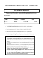
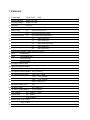
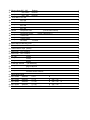
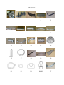
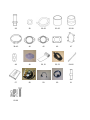
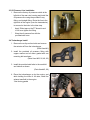
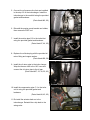
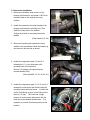
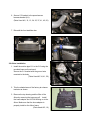
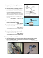
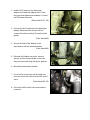
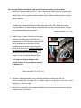
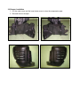
GReddy Turbo Kit
2003 Mazda RX-8 (13B-MSP)
T618Z 10cm2 (Actuator Type)
Emanage Ultimate
2003 Mazda RX-8 (13B-MSP)T618Z 10cm2 (Actuator Type)
Installation Manual
Please read the entire manual before installing this kit.
Application:
Make
Mazda
Model
Chassis
RX-8
Year
LA-SE3P
•
This GReddy Turbo Kit is designed only for the vehicles specified above.
•
Premium grade gasoline (91 octane or higher) is required with this Kit.
•
Make sure that the vehicle is not equipped with any ECU upgrade chips.
•
This kit is designed for High Power 6 speed manual transmission Vehicle only.
Important
1. This installation should only be performed by a trained specialist who is very
familiar with the automobile’s mechanical, electrical and fuel management
system.
2. If installed by an untrained person, it may cause damage to the kit as well as
the vehicle.
3. GReddy Performance Products Inc. is not responsible for any damage to the
vehicle’s electrical system caused by improper installation.
4. Make sure to follow the instruction and pay attention to the “Important”,
“Warning!” and “Caution!” notice through out the instruction.
5. Improper installation can be dangerous! Please make sure to inspect the
installation before operating the vehicle.
6. Call your GReddy Authorized dealer or GReddy Performance Products if
there are any problems or questions regarding this product.
2003
1. Parts List
1. Turbocharger
T618Z 10cm2
2. Exhaust Manifold
Ductile Iron Cast
1
3. Downpipe Adapter
Ductile Iron Cast
1
4. Intercooler
Type 31C
1
5. Intercooler Bracket
(Steel)
1
6. Suction Pipe
S-1
(80∅-60∅ Aluminum)
1
7.
S-2
(60∅ Aluminum with flange)
1
C-1
(50∅ Aluminum flange elbow )
1
“
8. Compression Pipe
P380
1
9.
“
C-2
(50∅ Aluminum)
1
10.
“
C-3
(50∅ Aluminum)
1
11.
“
C-4
(60∅ Aluminum elbow)
1
12.
“
C-5
(60∅ Aluminum)
1
13.
“
C-6
(80∅ Aluminum)
1
14. Airflow meter adapter X-4008 (Aluminum elbow)
1
15. Airinx
AY-MB (Blue)
1
16. Airinx
Hose Adapter 80∅
1
17.
"
Hose band #48
1
18.
"
Bracket (Steel)
1
19. Air Pump Pressure Hose
1
20. Down Pipe Adapter Bracket
1
21. Oil Pressure
Hose SUS
(800mm)
1
22. Oil Pressure Copper Washer 10∅ (t=1.0mm)
1
23. Oil Pressure Union Fitting
3-Way 1/8PT Fitting
1
24.
“
1/8PT – 1/8 PT Straight
1
25.
“
1/8PT – 1/8 PF Straight
1
26.
“
1/8PF – M10 P1.25
1
27. Oil Return Flange Tube
16∅
1
28. Oil Return Fitting
16∅ - M14 P1.5
1
29. Oil Return Copper Washer
14∅ (t=2.0mm)
1
30. Vacuum Hose
5∅ x 2000mm
31. Rubber Hose
9∅ x 450mm
1
32.
16∅ x 150mm
1
"
(Blue)
1
33. Rubber Hose 50∅ x 70mm
2
34.
"
60∅ x 70mm
3
35.
"
80∅ x 60mm
1
36. Silicone Hose 50∅ - 60∅
Reducer
1
37.
“
80∅ x 80∅
Reducer
1
38.
“
80∅ - 90∅
Reducer
1
39. Hose Band 16∅ #10
2
40.
“
50∅ #32
5
41.
“
60∅ #36
8
42.
“
80∅ #48
4
43.
“
90∅ #56
1
44. Gasket
Compressor Inlet
(Part # 14465-54C00)
1
45.
"
Compressor Outlet
46.
"
Turbine Inlet
1
47.
"
Turbine Outlet
1
48.
"
Oil Return
(Part # 14465-05U11)
1
TD Small
1
49. Intake Manifold Blocking Plate
1
50. Thermo Cloth
1
100mm x 250mm
51. Thermo Barrier Tape (14002)
1
52. Wire Loom
13∅ x 500mm
1
53. Wire Loom
19∅ x 250mm
1
54. Zip Ties
100mm
10
55.
"
150mm
5
56.
"
200mm
5
57. E-Manage Ultimate
(US-RX8 6MT)
1
58.
“
Plug-In Harness
1
59.
“
Pressure Sensor
1
60.
“
Pressure sensor Harness
1
61. Orifice Hose Fitting
1
62. M4 x 10mm
Stainless
P=0.7
B
2
63. M6 x 15mm
Stainless
P=1.0
B S/W F/W
-
4
64. M8 x 20mm
Stainless
P=1.25
B S/W F/W
N
2
65. M8 x 25mm
Stainless
P=1.25
B S/W F/W
-
4
66. M8 x 30mm
Stainless Stud P=1.25 – 1.25
B S/W
N
9
-
Part List
1
2
3
4
5
6
7
8
9
10
11
12
13
14
15
16
17
18
19
20
21
22
23
24~26
27
28
29
30~32
33~35
36~38
39~43
44
45
46
47
48
49
50, 51
52, 53
54~56
57
58
59
60
61
62-66
2. Factory Parts Removal
When removing the stock parts, please refer to the factory RX8
Workshop manual for proper procedures.
2-1 Factory Parts Removal
1. Remove the engine cover and the battery cover. Disconnect the negative terminal of
the battery.
2. Remove the battery, battery box, and battery tray.
3. Drain the engine oil.
4. Remove the front strut bar, air cleaner box, air cleaner insulator and intake pipe.
(RX8 Workshop Manual pages 01-13-2 ~ 01-13-6)
5. Remove the engine under cover, front inner fender, and front bumper.
(RX8 Workshop Manual pages 09-10-7)
6. Remove the Front Stabilizer Bar.
7. Remover the AIR pump, AIR Control Valve, and AIR Control pipe.
(RX8 Workshop Manual pages 01-16-2, 01-16-2, 01-16-8)
8. Remove the Transverse Member.
(RX8 Workshop Manual pages 02-13-18)
9. Disconnect the rear o2 sensor and remove the Cross Member, and Catalytic
Converter.
(RX8 Workshop Manual pages 01-15-2)
10. Disconnect the front O2 sensor and remove the Right Engine Mount Bracket, Right
Engine Mount Rubber and exhaust manifold using the SST tool to hold the engine.
(RX8 Workshop Manual pages 01-15-2 ~ 01-15-4)
3. Turbo Kit Installation
3-1 Intake Manifold Plate Installation
1. Remove the extension manifold (upper).
Please refer to RX8 workshop manual pages
01-13-4 to 01-13-11.
*
Make sure to prevent any dirt or objects from
entering the intake manifold.
2. Install the Intake Manifold Blocking Plate onto
the manifold as shown in the picture.
(Parts Used #49)
3. Apply silicone gasket to the manifold surface
shown in the picture. Make sure the manifold
is clean before installing. You do not need to
apply silicone gasket to factory o rings.
Replace O rings if necessary.
4. Install extension manifold back onto intake
manifold. Refer to RX8 workshop manual.
3-2 Thermo Cloth Installation
1. Apply the provided Thermo Tape to the fire wall
around the exhaust manifold. (To secure the
Thermo Tape, Apply Aluminum tape on the
edges)
2. Bend and push the heat shield on the chassis
more against the body.
(Parts Used #51)
Caution!
It is very important to protect the parts surrounding the exhaust manifold and turbo from high
temperature. Improper installation of the thermo barrier may cause damage and fire.
3-3 Oil Pressure Line Installation
1. Remove the factory oil pressure switch at the
left side of the rear rotor housing and install the
Oil pressure line using the provided 3 way
fitting, and straight fitting. Route the line to the
right side of the engine (over the transmission)
to connect to the turbo in the later step.
*
Apply Teflon tape on the PT thread in and
to not over tighten the fitting.
*
Wrap the oil pressure line with the
provided wire loom.
3-4 Turbocharger Install
1. Remove the e-clip and two bolts and remove
the actuator off from the turbocharger.
(Parts Used #1)
2. Install the provided oil pressure fitting with
copper washer and oil return gasket with one
mounting bolt as shown.
(Parts Used #22, 26, 48, 63)
3. Install the provided stud bolts to the manifold
and turbine as shown.
(Parts Used #2, 66)
4. Place the turbocharger up by the engine, and
while holding the turbo to the side, install the
exhaust manifold to the engine.
*Use factory gasket
5. Connect the oil pressure line that was installed
in the step 3-2 to the turbocharger. Install the
turbocharger to the manifold using the provided
gasket and hardware.
(Parts Used #46, 66)
6. Reinstall the engine mount bracket and rubber,
then remove the SST tool.
7. Install the suction pipe S-3 to the turbo inlet
using the provided gasket and hardware.
(Parts Used #7, 44, 65)
8. Replace the oil drain plug with the provided oil
return fitting and copper washer.
(Parts Used #28, 29)
9. Install the oil return pipe to the turbo charger.
Wrap the thermo cloth to the 16∅ hose and
connect the oil return pipe to the oil pan.
(Parts Used #27, 32, 39, 50, 63)
10. Install the compression pipe C-1 to the turbo
out let using the provided gasket and
hardware.
(Parts Used #8, 45, 65)
11. Re install the actuator back on to the
turbocharger. Reinstall the e-clip back to the
swing valve.
3-5 Intercooler Installation
1. Remove the auxiliary temp sensor on the
bumper reinforcement, and rotate it 180°, then
reinstall it back to the original mounting
location.
2. Install the intercooler mounting bracket to the
bumper reinforcement mounting bolt. Then
install the intercooler to the bracket.
*Adjust the bracket to mounting intercooler
parallel.
(Parts Used #4, 5, 64)
3. Remove the plastic part between the lower
radiator hose and bracket. Bend the bracket up
and secure it with zip ties as shown.
4. Install the compression pipe C-2 and C-3
between the C-1 to the intercooler with
provided hose and hose band.
Secure C-2 bracket to the speed sensor
harness bracket (RH).
(Parts Used #9, 10, 33, 36, 40, 41)
5. Install the compression pipe C-4, C-5, and C-6
between the intercooler and throttle using the
provided hoses and hose bands. Connect the
Jet Air Fuel Mixing sir hose to the fitting on the
back of C-6 pipe. This hose has a large
amount of suction when idling and is the top
hose that routes behind the alternator. It is
important to connect this hose properly to this
location.
6. Secure C-5 bracket to the speed sensor
harness bracket (LH).
(Parts Used #11, 12, 13, 34, 35, 37, 41, 42, 56)
7. Reinstall the front stabilizer bar.
3-6 Airinx Installation
1. Install the suction pipe S-1 tot he S-2 using the
provided hose and hose band.
Secure the S-1 bracket with the ground wire
mounted to the body.
(Parts Used #6, 34, 41, 50)
2. Trim the shaded area of the factory air cleaner
insulator as shown.
3. Remove the top housing and the filter of the
Airinx by removing the top screw off. Install
the hose adapter and 10∅-M18 fitting on to the
Airinx. Make sure that the hose adapter is
properly install on the Airinx frame.
(Parts Used #15, 16)
4. Assemble the Airinx back together and hand
tight the top screw.
5. Remove the factory Airflow meter off from the
air cleaner box and install the Airflow mete to
the provided air flow meter adapter. Install the
Airinx and the adapter to suction Pipe S-1.
* The O-ring on the Airflow meter will be reused.
Apply some grease on the O-ring on the Airflow
meter, and make sure not to damage when
installing.
(Parts Used #14, 17, 38, 42, 43, 62)
Airflow
Sensor
6. Secure the Airinx with the provided bracket and
connect the Airflow meter connector.
(Parts Used #18)
7. Connect the air hose from the Metering Oil
Sensor
FLOW
Attachment
Pump to suction pipe S-1.
(Parts Used #31)
Do not mistake this for the Jet Air Fuel Mixing hose.
8. Connect the Engine by pass hose on the Oil
filler pipe to the suction pipe S-1
(Parts Used #31)
Do not mistake this for the Jet Air Fuel Mixing hose.
3-7 Air Pump and Exhaust Installation
1. Install the provided Air Pump Hose to the factory AIR control valve and install the valve
back to the original location. And route the Air Pump Hose over the turbocharger.
*Use the factory gasket and bolts.
(Parts Used #20)
2. Install the O2 sensor to the down pipe
adapter and install the adapter to the Turbo
using provided gasket and hardware. Connect
the O2 sensor connector.
(Parts Used #3, 47, 66)
3. Connect the Air Pump hose to the down pipe
adapter. Bend the hose so that it will not
contact the turbine housing. Re-use the stock
gasket.
(Parts Used #63)
4. Secure the Down Pipe Adapter to the
transmission with the provided bracket.
(Parts Used #20)
5. Reinstall the Catalytic converter, exhaust
system, and the cross member in the order
they were removed using the factory gaskets.
6. Reinstall the transverse member.
7. Cover the Air pump hose with provided wire
loom and connect the hose for the AIR control
valve.
(Parts Used #53, 56)
8. Connect the AIR control valve hose and the
connector.
3-8 e-manage Ultimate installation and vacuum hose connection for the actuator.
1. Remove the washer tank and drill a 1" hole on the fire wall. Make sure not to drill through
any thing on the other side. There is a hump on the fire with a circle indentation behind the
washer tank, which would be a perfect location to drill. Install a rubber grommet to protect
the wire harness.
2. Remove the PCM cover and disconnect the Main harness from the PCM. Connect the
provided plug-in harness between the Main harness and the PCM. Route the harness
along the fender in to the passenger compartment through the hole that was cut. Connect
the e-manage Ultimate to the harness.
(Parts Used #54, 55, 57, 58)
3. Install a vacuum hose to the port on the intake
manifold (right after the throttle) that was
connected to the VFAD actuator (removed with
the Air cleaner box) and connect it to the
provided pressure sensor with the provided
Orifice Fitting
orifice hose fitting in line. Install the fitting with
the orifice facing toward the manifold. Route
the harness with the e-manage harness and
connect it to the e-manage Ultimate Option
Port #1.
*You may have engine damage if the
pressure sensor is not connected properly
to Option Port 1.
*secure vacuum hose with provided zip ties.
(Parts Used #30, 54, 59, 60, 61)
4. Stick the e-manage emblem on the e-manage Ultimate unit and mount the unit.
*Avoid mounting the e-manage unit in a place where it can get wet or wet. Also, avoid
exposing it to direct sun light.
5. Remove the rubber plug on the intake manifold and connect a vacuum hose from this port
to the actuator on the turbo.
3-9 Bumper installation
1. Cut the under cover and the inner fender cover to clear the compression pipe.
2. Reinstall the front bumper.
Starting the Engine
1. Reinstall the battery tray, battery box, battery, and connect the positive terminal only.
2. Reinstall the front strut tower bar.
3. Refill the engine oil and inspect the hoses and wire connection, then connect the negative
terminal of the battery.
4. Turn the ignition to “ON” position and confirm that the "ACTIVE" L.E.D. lights up GREEN.
5. Remove the ECM fuse and crank the engine to get oil pressure to the turbo. (Until the oil light
on the dash turns off) Check for any oil leaks, then reinstall the fuse and start the engine.
6. While idling, check for any oil, coolant, or air leaks.
7. After inspection, reinstall the under cover and other stock parts that was removed.
8. On the initial run, be sure to have a boost gauge to check the turbo-actuator setting. This turbo
kit is preset to boost between 0.4kg/cm2 to 0.45kg/cm2 .
It is very important that you monitor the boost pressure, and make sure not to over boost.
Over boosting can cause engine damage.
This completes the Turbo Kit installation.
• Important!
•
It is very important that you monitor the boost pressure, and make sure not to over
boost. Over boosting can cause engine damage.
•
Please ensure that the vehicle is in proper working order before installing this kit. This
kit will not operate properly if the vehicle is not in optimum operating condition.
•
GReddy Performance Products, Inc. is not responsible for any engine damage caused
by over boosting (increased boost), modification to the kit, and/or misuse of the product.
NO WARRANTY is offered.
•
Due to lack of control over proper installation and use of this product,
NO WARRANTY is offered for this kit.
e-manage Ultimate Information
Important!
•
The e-manage Ultimate included in this kit is preprogrammed for this turbo kit.
•
•
Do not attempt to adjust any of the settings or dip switches on the e-manage Ultimate.
Any adjustments made can cause damage to the e-manage Ultimate, engine and the
factory ECU.