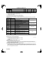
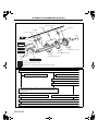
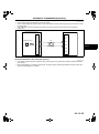
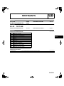
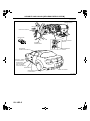
1
2006
Mazda
RX-8
Service
Highlights
FOREWORD
This manual explains components, system
operations and functions for the Mazda RX-8.
For proper repair and maintenance, a thorough
familiarization with this manual is important,
and it should always be kept in a handy place
for quick and easy reference.
All the contents of this manual, including
drawings and specifications, are the latest
available at the time of printing.
As modifications affecting repair or
maintenance occur, relevant information
supplementary to this volume will be made
available at Mazda dealers.
This manual should be kept up-to-date.
Mazda Motor Corporation reserves the right to
alter the specifications and contents of this
manual without obligation or advance notice.
All rights reserved. No part of this book may be
reproduced or used in any form or by any
means, electronic or mechanical—including
photocopying and recording and the use of any
kind of information storage and retrieval
system—without permission in writing.
Mazda Motor Corporation
HIROSHIMA, JAPAN
APPLICATION:
This manual is applicable to vehicles
beginning with the Vehicle Identification
Numbers (VIN), and related materials shown
on the following page.
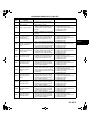
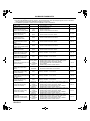
CONTENTS
Title
Section
GENERAL INFORMATION
00
ENGINE
01
SUSPENSION
02
DRIVELINE/AXLE
03
BRAKES
04
TRANSMISSION/TRANSAXLE
05
STEERING
06
HEATER, VENTILATION &
AIR CONDITIONING (HVAC)
07
RESTRAINTS
08
BODY & ACCESSORIES
09
© 2005 Mazda Motor Corporation
PRINTED IN U.S.A., OCTOBER 2005
Form No. 3409–1U–05J
Part No. 9999–95–102F–06
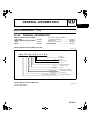
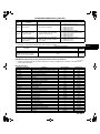
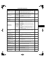
VEHICLE IDENTIFICATION NUMBERS (VIN)
JM1 FE173✻6#
JM1 FE17N✻6#
200001—
200001—
RELATED MATERIALS
Material Name
MNAO Part No.
Mazda Material No.
2004 Mazda RX-8 Service Highlights
9999–95–102F–04
3378–1U–03C
2005 Mazda3, Mazda MX-5 Miata/MX-5, MAZDASPEED MX-5,
Mazda MPV, Mazda RX-8 Service Highlights
9999–95–MODL–05
3400–1U–04H
1995, 1996, 1997, 1998, 1999, 2000 OBD-II Service Highlights
9999–95–OBD2–00
3344–1U–99K
2006 Mazda RX-8 Workshop Manual
9999–95–064B–06
1857–1U–05J
Engine Workshop Manual 13B-MSP
9999–95–E13B–MSP
1773–1U–03C
9999–95–T15M–D
1774–1U–03C
Automatic Transmission Workshop Manual RC4A-EL
9999–95–RC4A–EL
1775–1U–03C
2004 Mazda RX-8 Bodyshop Manual
9999–95–120F–04
3379–1U–03D
2006 Mazda RX-8 Wiring Diagram
9999–95–040G–06
5650–1U–05J
Manual Transmission Workshop Manual Y16M-D
00
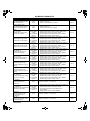
GENERAL INFORMATION
SECTION
Toc
of SCT INFORMATION . . . . 00-00
GENERAL
Toc of SCT
00–00
GENERAL INFORMATION
Conversion to SI Units (Système
International d'Unités) . . . . . . . . . . . .
Rounding Off . . . . . . . . . . . . . . . . . . . .
Upper and Lower Limits . . . . . . . . . . . .
SAE STANDARD . . . . . . . . . . . . . . . . . . .
VEHICLE IDENTIFICATION NUMBER
(VIN) CODE . . . . . . . . . . . . . . . . . . . . . . 00–00–1
VEHICLE IDENTIFICATION NUMBER
(VIN) . . . . . . . . . . . . . . . . . . . . . . . . . . . . 00–00–1
UNITS . . . . . . . . . . . . . . . . . . . . . . . . . . . . 00–00–2
00–00–2
00–00–2
00–00–2
00–00–3
End of Toc
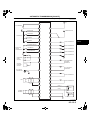
VEHICLE IDENTIFICATION NUMBER (VIN) CODE
EHU000000000105
J M1 FE17N *6 # 1 2 3 4 5 6
Serial No.
Plant
0= Hiroshima
1= Hofu
Model year
4=2004, 5=2005...
Check Digit
*=0 to 9, X
Engine
Body style
Restraint system
Carline, series
World manufacturer identification
N= 13B-Standard power
3= 13B-High power
7= Coupe
1=Driver, Passenger Airbag,
Side Airbag, Curtain Airbag
FE= Mazda RX-8
JM1= Mazda/passenger car
EHU000ZW8008
End Of Sie
VEHICLE IDENTIFICATION NUMBER (VIN)
EHU000000000106
JM1 FE173*6# 200001—
JM1 FE17N*6# 200001—
End Of Sie
00–00–1
00–00
GENERAL INFORMATION
UNITS
Electrical current
Electric power
Electric resistance
Electric voltage
Length
Negative pressure
Positive pressure
Torque
Volume
Weight
EHU000000000103
A (ampere)
W (watt)
ohm
V (volt)
mm (millimeter)
in (inch)
kPa (kilo pascal)
mmHg (millimeters of mercury)
inHg (inches of mercury)
kPa (kilo pascal)
kgf/cm2 (kilogram force per square
centimeter)
psi (pounds per square inch)
N·m (Newton meter)
kgf·m (kilogram force meter)
kgf·cm (kilogram force centimeter)
ft·lbf (foot pound force)
in·lbf (inch pound force)
L (liter)
US qt (U.S. quart)
Imp qt (Imperial quart)
ml (milliliter)
cc (cubic centimeter)
cu in (cubic inch)
fl oz (fluid ounce)
g (gram)
oz (ounce)
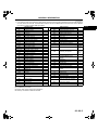
Conversion to SI Units (Système International d'Unités)
• All numerical values in this manual are based on SI units. Numbers shown in conventional units are converted
from these values.
Rounding Off
• Converted values are rounded off to the same number of places as the SI unit value. For example, if the SI unit
value is 17.2 and the value after conversion is 37.84, the converted value will be rounded off to 37.8.
Upper and Lower Limits
• When the data indicates upper and lower limits, the converted values are rounded down if the SI unit value is
an upper limit and rounded up if the SI unit value is a lower limit. Therefore, converted values for the same SI
unit value may differ after conversion. For example, consider 2.7 kgf/cm2 in the following specifications:
210—260 kPa {2.1—2.7 kgf/cm2, 30—38 psi}
270—310 kPa {2.7—3.2 kgf/cm2, 39—45 psi}
• The actual converted values for 2.7 kgf/cm2 are 265 kPa and 38.4 psi. In the first specification, 2.7 is used as
an upper limit, so the converted values are rounded down to 260 and 38. In the second specification, 2.7 is
used as a lower limit, so the converted values are rounded up to 270 and 39.
End Of Sie
00–00–2
GENERAL INFORMATION
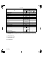
SAE STANDARD
EHU000000000104
• In accordance with new regulations, SAE (Society of Automotive Engineers) standard names and abbreviations
are now used in this manual. The table below lists the names and abbreviations that have been used in Mazda
manuals up to now and their SAE equivalents.
Abbreviation
AP
APP
ACL
A/C
BARO
B+
CMP sensor
CAC
CLS
CTP
CPP
CIS
CKP sensor
DLC
DTM
DTC
DI
DLI
EI
ECT
EM
EVAP
EGR
FC
FF
4GR
GEN
GND
HO2S
IAC
IAT
KS
MIL
SAE Standard
Remark
Name
Accelerator Pedal
Accelerator Pedal Position
Air Cleaner
Air Conditioning
Barometric Pressure
Battery Positive Voltage
Camshaft Position Sensor
Charge Air Cooler
Closed Loop System
Closed Throttle Position
Clutch Pedal Position
Continuous Fuel Injection System
Crankshaft Position Sensor
Data Link Connector
Diagnostic Test Mode
#1
Diagnostic Test Code(s)
Distributor Ignition
Distributorless Ignition
Electronic Ignition
#2
Engine Coolant Temperature
Engine Modification
Evaporative Emission
Exhaust Gas Recirculation
Fan Control
Flexible Fuel
Fourth Gear
Generator
Ground
Heated Oxygen Sensor
Idle Air Control
Intake Air Temperature
Knock Sensor
Malfunction Indicator Lamp
With
heater
Abbreviation
MAP
MAF sensor
MFL
OBD
OL
OC
O2S
PNP
PSP
PCM
SAE Standard
Name
Manifold Absolute Pressure
Mass Air Flow Sensor
Multiport Fuel Injection
On-board Diagnostic System
Open Loop
Oxidation Catalytic Converter
Oxygen sensor
Park/Neutral Position
Power Steering Pressure
Powertrain Control Module
Remark
#3
PAIR
Pulsed Secondary Air Injection
Pulsed
injection
AIR
Secondary Air Injection
Injection
with air
pump
SAPV
SFI
3GR
TWC
TB
TP sensor
TCC
Secondary Air Pulse Valve
Sequential Multiport Fuel
Injection
Third Gear
Three Way Catalytic Converter
Throttle Body
Throttle Position Sensor
Torque Converter Clutch
TCM
Transmission (Transaxle) Control
Module
TR
TC
VSS
VR
VAF sensor
Transmission (Transaxle) Range
Turbocharger
Vehicle Speed Sensor
Voltage Regulator
Volume Air Flow Sensor
WU-TWC
WOP
Warm Up Three Way Catalytic
Converter
#4
Wide Open Throttle
#1: Diagnostic trouble codes depend on the diagnostic test mode.
#2: Controlled by the PCM
#3: Device that controls engine and powertrain
#4: Directly connected to exhaust manifold
End Of Sie
00–00–3
00–00
2006 Mazda RX-8 Service Highlights (3409–1U–05J)
01
ENGINE
SECTION
01–00
Toc
of SCT . . . . . . . . . . . . . . . . . . 01-00
OUTLINE
INTAKE-AIR SYSTEM . . . . . . . 01-13
ON-BOARD DIAGNOSTIC . . . . 01-02
Toc of SCT
01–00
OUTLINE
ENGINE ABBREVIATIONS . . . . . . . . . . . 01–00–1
ENGINE FEATURES . . . . . . . . . . . . . . . . 01–00–1
ENGINE SPECIFICATIONS. . . . . . . . . . . 01–00–2
End of Toc
ENGINE ABBREVIATIONS
A/C
APV
CCM
DC
CSERS
FP1
KOEO
KOER
L/F
L/R
MT
RP1
SSV
SW
T/F
T/R
VDI
VFAD
EHU010002000101
Air Conditioner
Auxiliary Port Valve
Comprehensive Component Monitor
Drive Cycle
Cold Start Emission Reduction Strategy
Front Primary 1
Key On Engine Off
Key On Engine Running
Leading Front
Leading Rear
Manual Transmission
Rear Primary 1
Secondary Shutter Valve
Switch
Trailing Front
Trailing Rear
Variable Dynamic Effect Intake
Variable Fresh Air Duct
End Of Sie
ENGINE FEATURES
To meet OBD-II regulations
EHU010002000102
• Modes 01, 02, 03, and 06 of diagnostic test modes changed
End Of Sie
Revised 4/2006 (Ref. No. R027/06)
01–00–1
2006 Mazda RX-8 Service Highlights (3409–1U–05J)
OUTLINE
ENGINE SPECIFICATIONS
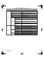
EHU010002000103
Specification
2006MY Mazda RX-8
2005MY Mazda RX-8
13B-MSP
13B-MSP
13B-MSP
13B-MSP
(Standard
(High
(Standard
(High
power)
power)
power)
power)
Item
MECHANICAL
Engine type
Rotor arrangement and number
Combustion chamber type
Displacement
Compression ratio
Compression pressure
Open
IN
Port timing
Close
Rotary
In-line 2-rotor, longitudinal
Bathtub
(ml {cc, cu in})
654 {654, 40.0}×2
10.0
830 {8.5, 120}[250]
←
3°
12°
3°
←
←
←
←
←
←
←
←
Force-fed type
Trochoid gear
←
←
441—490
{4.5—5.0, 64.0—71.0}
←
Full-flow
←
(kPa {kgf/cm psi}
)
78—118
{0.8—1.2, 11.4—17.1}
←
(kPa {kgf/cm2, psi} [rpm] )
350 {3.57, 50.8} [3,000]
←
3.3 {3.5, 2.9}
3.5 {3.7, 3.1}
4.7 {5.0, 4.1}
5.7 {6.0, 5.0} 6.4 {6.7, 5.6}
SL
5W–20
GF–3
←
←
←
←
←
←
←
Water-cooled, forced
circulation
9.8 {10.4, 8.6}
Centrifugal, V-ribbed beltdriven
Wax
80—84 {176—183}
95 {203}
8.5 {0.33} or more
Corrugated fin
←
(kPa {kgf/cm2, psi} [rpm])
Primary port
Secondary port ATDC
Auxiliary port
Primary port
Secondary port ABDC
Auxiliary port
BBDC
BTDC
Open
Close
LUBRICATION SYSTEM
Type
Type
Oil pump
Relief valve opening pressure
(approx. quantity)
EX
(kPa {kgf/cm2, psi}
)
Type
Oil filter
Relief valve opening pressure
(approx. quantity)
Oil pressure (approx.
quantity)
[oil temperature 100°C
{212°F}]
2,
Oil replacement
Oil capacity
(approx. quantity)
Oil and oil filter replacement
(L {US qt, lmp qt}) Engine overhaul
Total (dry engine)
API service
Recommended oil
SAE viscosity
ILSAC
COOLING SYSTEM
Type
Coolant capacity
(L {US qt, lmp qt})
Water pump
Type
Opening temperature
(°C {F°})
Thermostat
Full-open temperature
(°C {F°})
Full-open lift
(mm {in})
Radiator
Type
Cap valve opening pressure
Cooling system cap
(kPa {kgf/cm2, psi} )
01–00–2
←
←
←
←
←
–
60°
45°
–
40°
38°
65°
36°
80°
50°
73.3—103.3 {0.748—
1.053, 10.63—14.98}
←
←
←
←
←
←
←
←
←
OUTLINE
Item
Type
Cooling fan
Number of blades
Outer diameter
(mm {in})
Specification
2006MY Mazda RX-8
2005MY Mazda RX-8
13B-MSP
13B-MSP
13B-MSP
13B-MSP
(High
(Standard
(High
(Standard
power)
power)
power)
power)
Electronic
←
Cooling fan No.1: 5,
←
Cooling fan No.2: 7
300 {11.8}
←
FUEL SYSTEM
Injector
Type
Type of fuel delivery
Type of drive
Pressure regulator control
pressure
Fuel pump type
Fuel tank capacity (approx.
quantity)
(kPa {kgf/cm2, psi})
(L {US gal, lmp gal})
Fuel type
EMISSION SYSTEM
AIR system
←
←
←
Approx. 390 {3.98, 56.6}
←
Electric
←
60 {15.9, 13.2}
←
Unleaded premium
(unleaded high-octane)
gasoline
←
Air pump, air control valve
Three-way catalyst
(monolithic)
Canister design
Closed design
Catalyst type
EVAP control system
PCV system
CHARGING SYSTEM
Voltage
Battery
Type and capacity
(5 hour rate)
Out-put
Generator
Regulated voltage
Self diagnosis function
IGNITION SYSTEM
(V)
12
(A·h)
75D23L (52)
(V–A)
(V)
12—100
Controlled by PCM
Distributorless Ignition
(DLI)
Electronic
When idling:
T/F-L/F-T/R-L/R
Except for idling:
L/F-T/F-L/R-T/R
(Independent ignition
control)
Type
Spark advance
Ignition system
Firing order
Spark plug
Multiple hole design
Top-feed
Electronic
←
←
←
←
←
←
50D20L (40), 55D23L (48)
75D23L (52), 75D26L (52)
←
←
←
←
←
←
Leading side
N3H5 18 110 (RE7C-L)*1,
N3Y8 18 110 (RE7C-L)*1,
N3Y9 18 110 (RE6C-L)*2
N3H2 18 110C
(RE7A-L)*1,
N3Y2 18 110 (RE7A-L)*1,
N3Y3 18 110 (RE6A-L)*2,
N3H5 18 110 (RE7C-L)*1,
N3Y8 18 110 (RE7C-L)*1,
N3Y9 18 110 (RE6C-L)*2
Trailing side
N3H1 18 110C
(RE9B-T)*1,
N3Y1 18 110 (RE9B-T)*1
←
Type
STARTING SYSTEM
Type
Starter
Output
Coaxial reduction
(kW)
2.0
←
AT: 1.8*3, MT: 1.4*3
2.0*4
01–00–3
01–00
OUTLINE
Item
CONTROL SYSTEM
Neutral switch (MT)
CPP switch (MT)
SSV switch
APV position sensor
ECT sensor
IAT sensor
TP sensor
APP sensor
MAF sensor (Inside MAF)
Front HO2S
Rear HO2S
BARO sensor
KS
Eccentric shaft position sensor
Metering oil pump switch
Brake switch
Throttle valve actuator
APV motor
Fuel injector (primary 1)
Fuel injector (secondary)
Fuel injector (primary 2)
Stepping motor (in metering oil pump)
Specification
2006MY Mazda RX-8
2005MY Mazda RX-8
13B-MSP
13B-MSP
13B-MSP
13B-MSP
(High
(Standard
(High
(Standard
power)
power)
power)
power)
ON/OFF
ON/OFF
ON/OFF
–
Hall element
Thermistor
Thermistor
Hall element
Hall element
Hot-wire
Zirconia element (all range
air/fuel ratio sensor)
Zirconia element
(Stoichiometric air/fuel
ratio sensor)
Piezoelectric element
Piezoelectric element
Magnetic pickup
ON/OFF
ON/OFF
DC motor
–
DC motor
Multiple hole type (12
holes)
Multiple hole type (4 holes)
Multiple hole
–
type
(4 holes)
Stepping motor
←
←
←
←
←
←
←
←
←
←
←
←
←
←
←
←
←
←
←
←
←
←
*1 : Standard equipment
*2 : Hot type plug: Available only for customers who often drive their car at very low speed which causes the plugs
to foul easily.
*3 : Applied VIN (Assumed)
JM1 FE173*5# 100001–150736
JM1 FE17N*5# 100001–150736
*4 : Applied VIN (Assumed)
JM1 FE173*5# 150737–
JM1 FE17N*5# 150737–
End Of Sie
01–00–4
ON-BOARD DIAGNOSTIC
01–02
ON-BOARD DIAGNOSTIC
ON-BOARD DIAGNOSTIC OUTLINE . . .
Features . . . . . . . . . . . . . . . . . . . . . . . .
ON-BOARD DIAGNOSTIC
WIRING DIAGRAM . . . . . . . . . . . . . . . .
DIAGNOSTIC TEST MODE. . . . . . . . . . .
On-board system readiness test . . . . .
OBD-II Freeze Frame Data
(Mode 02). . . . . . . . . . . . . . . . . . . . . .
01–02–1
01–02–1
01–02–2
01–02–4
01–02–4
01–02–4
OBD-II Diagnostic Trouble Code
(Mode 03) . . . . . . . . . . . . . . . . . . . . . . 01–02–5
OBD-II Diagnostic Monitoring System
Test Results (Mode 06) . . . . . . . . . . . . 01–02–8
DTC DETECTION LOGIC AND
CONDITIONS . . . . . . . . . . . . . . . . . . . . . 01–02–8
KOEO/KOER SELF-TEST . . . . . . . . . . . . 01–02–9
PID/DATA MONITOR AND RECORD . . . . 01–02–12
SIMULATION TEST . . . . . . . . . . . . . . . . . 01–02–14
End of Toc
ON-BOARD DIAGNOSTIC OUTLINE
EHU010200000101
Features
To meet OBD-II regulations
• Modes 02, 03, and 06 of diagnostic test modes changed
End Of Sie
01–02–1
01–02
ON-BOARD DIAGNOSTIC
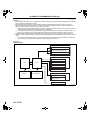
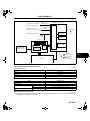
ON-BOARD DIAGNOSTIC WIRING DIAGRAM
EHU010200000107
IG2
IG1
FUEL PUMP RELAY
STARTER RELAY
5A
5P
START
ACC
FUEL PUMP
SPEED CONTROL RELAY
5J
MAIN RELAY
4M
4E
5AC
FUEL PUMP RESISTOR
5AF
BATTERY
FUEL INJECTOR (FP)
IGNITION RELAY
2M
FUEL INJECTOR (FS)
4Q
2G
DRIVE-BY-WIRE RELAY
FUEL INJECTOR (RP)
2J
5H
4C
FUEL INJECTOR (RS)
2D
2
CPP SWITCH *
FUEL INJECTOR (FP2) *1
4F
3A
NEUTRAL SWITCH *2
FUEL INJECTOR (RP2) *1
2O
3D
BRAKE SWITCH *3
4P
PCM
2AD
IGNITION COIL (T/F)
2AC
IGNITION COIL (T/R)
2AA
IGNITION COIL (L/F)
2Z
IGNITION COIL (L/R)
CRUISE CONTROL SWITCH *3
5V
4U
METERING OIL PUMP SWITCH
2N
METERING OIL PUMP
SSV SWITCH
1D
2W
REFRIGERANT PRESSURE SWITCH
2V
A/C
AMPLIFIER
HI, LO
MIDDLE
4W
2AB
4Z
OIL LEVEL SWITCH
2Y
2R
OIL-PRESSURE SWITCH
4H
2E
COOLANT LEVEL SWITCH
4T
d
c
a
b
4D
EVAP SYSTEM
LEAK DETECTION
PUMP
*1: 13B-MSP (HIGH POWER)
*2: MT
*3: WITH CRUISE CONTROL SYSTEM
EHU140ZT8003
01–02–2
ON-BOARD DIAGNOSTIC
c
a
b
c
d
ECT SENSOR
VFAD SOLENOID VALVE *1
2K
MAF SENSOR
5Z
5U
VDI SOLENOID VALVE
1W
5N
01–02
SSV SOLENOID VALVE
5K
1L
IAT SENSOR
PURGE SOLENOID VALVE
BARO SENSOR
2P
5S
AIR SOLENOID VALVE
1O
4K
KS
AIR PUMP RELAY
1T
4O
1F
1G
AIR PUMP
1U
APP SENSOR
4Y
NO.1
2I
5F
GENERATOR
2T
5AE
4X
NO.2
A/C AMPLIFIER
5W
5C
5AB
THROTTLE BODY
TP SENSOR
A/C RELAY
1Q
NO.1
1J
NO.2
1M
PCM
5AA
COOLING FAN RELAY NO.1
5X
2F
THROTTLE ACTUATOR
1C
COOLING FAN RELAY NO.2
5AD
1B
APV MOTOR *1
APV
POSITION
SENSOR
APV MOTOR
COOLING FAN RELAY NO.3
1S
3B
3J
4V
CAN_H
3G
ECCENTRIC SHAFT POSITION SENSOR
2U
4S
2X
CAN_L
OTHER MODULE
·EPS CONTROL MODULE
·TCM
·ABS HU/CM
·DSC HU/CM
·KEYLESS CONTROL MODULE
·TPMS CONTROL MODULE
·STEERING ANGLE SENSOR
·INSTRUMENT CLUSTER
2H
2B
4A
2C
4J
1V
5D
FRONT HO2S
REAR HO2S
5O
2Q
5R
2A
5T
*1: 13B-MSP (HIGH POWER)
EHU140ZT8004
End Of Sie
01–02–3
ON-BOARD DIAGNOSTIC
DIAGNOSTIC TEST MODE
• The diagnostic test mode is essentially carried over from that of the 2005 MY except for following.
— To meet OBD-II regulations, modes 02, 03, and 06 have been changed.
Diagnostic test mode
Mode 01
Mode 02
Mode 03
Mode 04
Mode 06
Mode 07
Mode 08
Mode 09
EHU010200000102
Item
Sending diagnostic data (PID data monitor/On-board system readiness test)
Sending freeze frame data
Sending emission-related malfunction code (DTC)
Clearing/resetting emission-related malfunction information
Sending intermittent monitoring system test results (DMTR)
Sending continuous monitoring system test results (pending code)
On-board device control (simulation test, active command mode)
Request vehicle information
On-board system readiness test
• The items supported by the on-board system readiness test are shown below.
Continuous monitoring system
— HO2S heater
— Thermostat
— Fuel system
— Misfire
— CCM
Intermittent monitoring system
— HO2S
— AIR system
— Catalyst
— EVAP system
— Engine cooling system
— CSERS
OBD-II Freeze Frame Data (Mode 02)
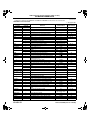
• Differences between the 2006 MY and 2005 MY Freeze Frame Data monitor items are shown below.
Freeze Frame Data monitor table
X: Applicable
—: Not applicable
2006 MY
X
X
X
X
X
X
X
X
X
X
X
X
X
X
X
X
X
X
X
X
X
X
X
01–02–4
2005 MY
X
X
X
X
X
X
X
X
X
X
X
X
X
—
X
X
X
X
X
X
X
X
X
Full names
DTC that caused required Freeze Frame Data storage
Fuel system status
Calculated LOAD Value
Engine Coolant Temperature
Short term fuel trim
Long term fuel trim
Engine RPM
Vehicle Speed Sensor
Ignition Timing Advance
Intake Air Temperature
Air Flow Rate from Mass Air Flow Sensor
Absolute Throttle Position
Commanded Secondary Air Status
Rear HO2S
Time since engine start
Commanded Evaporative Purge
Fuel Level Input
Number of warm-ups since DTCs cleared
Distance travelled since DTCs cleared
Barometric Pressure
Catalyst Temperature
Control module voltage
Absolute load value
Unit
—
Refer to list below.
%
°C
°F
%
%
rpm
km/h
mph
°
°C
°F
g/s
%
—
%
s
%
%
—
km
miles
kPa
°C
°F
V
%
ON-BOARD DIAGNOSTIC
2006 MY
X
X
X
X
X
X
X
2005 MY
X
X
X
X
X
X
X
Full names
Commanded Equivalence Ratio
Relative Throttle Position
Ambient air temperature
Absolute Throttle Position No.2
Accelerator Pedal Position No.3
Accelerator Pedal Position No.4
Commanded Throttle Actuator Control
Unit
—
%
°C
%
%
%
%
01–02
Meaning of fuel system loop status
• The following information is displayed on the tester.
— Feedback operating: HO2S being used for feedback is normal.
— Feedback stops: ECT is lower than the determined feedback zone.
— Feedback stops: Open loop due to driving condition.
— Feedback stops: Open loop due to detected system fault.
OBD-II Diagnostic Trouble Code (Mode 03)
• The following DTCs have been adopted.
— P0116, P0134, P0137, P0411, P050A
• Differences between the 2006 MY and 2005 MY DTCs are shown below.
DTC table
DTC No.
2006 MY 2005 MY
P0030
←
P0031
←
P0032
←
P0037
←
P0038
←
P0076
←
P0077
←
P0101
←
P0102
←
P0103
←
P0107
←
P0108
←
P0111
←
P0112
←
P0113
←
P0116*3
×: Applicable
—: Not applicable
MIL
DC
Front HO2S heater control circuit problem
Front HO2S heater control circuit low
Front HO2S heater control circuit high
Rear HO2S heater control circuit low
Rear HO2S heater control circuit high
VDI solenoid valve control circuit low
VDI solenoid valve control circuit high
MAF sensor circuit range/performance problem
MAF sensor circuit low input
MAF sensor circuit high input
BARO sensor circuit low input
BARO sensor circuit high input
IAT sensor circuit range/performance problem
IAT sensor circuit low input
IAT sensor circuit high input
ON
ON
ON
ON
ON
OFF
OFF
ON
ON
ON
ON
ON
ON
ON
ON
2
2
2
2
2
2
2
2
1
1
1
1
2
1
1
—
Engine coolant temperature circuit range/
performance
ON
2
P0117
P0118
P0122
P0123
←
←
←
←
ECT sensor circuit low input
ECT sensor circuit high input
TP sensor No.1 circuit low input
TP sensor No.1 circuit high input
ON
ON
ON
ON
1
1
1
1
P0125
←
Insufficient coolant temperature for closed loop fuel
control
ON
2
P0126
P0130
P0131
P0132
P0133
←
←
←
←
←
Insufficient coolant temperature for stable operation
Front HO2S circuit problem
Front HO2S circuit low voltage
Front HO2S circuit high voltage
Front HO2S circuit slow response
ON
ON
ON
ON
ON
2
2
2
2
2
Monitor
item*1
HO2S heater
HO2S heater
HO2S heater
HO2S heater
HO2S heater
Other
Other
CCM
CCM
CCM
CCM
CCM
CCM
CCM
CCM
Engine
cooling
system
CCM
CCM
CCM
CCM
Engine
cooling
system
Thermostat
HO2S
HO2S
HO2S
HO2S
P0134*3
—
Front HO2S no activity detected
ON
2
*3
—
Rear HO2S circuit low input
ON
←
Rear HO2S circuit high voltage
ON
P0137
P0138
Condition
Self -test Memory
function
type*4
C, O, R
×
C, O, R
×
C, O, R
×
C, O, R
×
C, O, R
×
C, O, R
×
C, O, R
×
C
×
C, O, R
×
C, O, R
×
C, O, R
×
C, O, R
×
C
×
C, O, R
×
C, O, R
×
C
×
C, O, R
C, O, R
C, O, R
C, O, R
×
×
×
×
C
×
C
C, O, R
C, O, R
C, O, R
C
×
×
×
×
×
HO2S
C, R
×
2
HO2S
C
×
2
HO2S
C, R
×
01–02–5
ON-BOARD DIAGNOSTIC
DTC No.
2006 MY 2005 MY
P0139
←
P0171
←
P0172
←
P0222
←
P0223
←
Condition
Rear HO2S circuit slow response
System too lean
System too rich
TP sensor No.2 circuit low input
TP sensor No.2 circuit high input
P0300
←
Random misfire detected
P0301
←
Front rotor misfire detected
P0302
←
Rear rotor misfire detected
P0327
P0328
P0335
←
←
←
P0336
←
P0410
←
MIL
DC
ON
ON
ON
ON
ON
Flas
h/ON
Flas
h/ON
Flas
h/ON
ON
ON
ON
2
2
2
1
1
1 or
2
1 or
2
1 or
2
1
1
1
ON
Monitor
item*1
HO2S
Fuel system
Fuel system
CCM
CCM
Self -test Memory
function
type*4
C, R
×
C, R
×
C, R
×
C, O, R
×
C, O, R
×
Misfire
C
×
Misfire
C
×
Misfire
C
×
CCM
CCM
CCM
C, O, R
C, O, R
C
×
×
×
1
CCM
C, R
×
ON
2
AIR system
C, R
×
ON
2
AIR system
C
×
ON
ON
ON
ON
ON
ON
2
2
2
2
2
2
Catalyst
EVAP system
EVAP system
CCM
EVAP system
EVAP system
C
C, R
C, R
C, R
C, R
C, R
×
×
×
×
×
×
ON
2
EVAP system
C, R
×
P0420
P0441
P0442
P0443
P0446
P0455
←
←
←
←
←
←
KS circuit low input
KS circuit high input
Eccentric shaft position sensor circuit problem
Eccentric shaft position sensor circuit range/
performance problem
Secondary air injection system problem
Secondary air injection system incorrect upstream
flow
Catalyst system efficiency below threshold
EVAP system incorrect purge flow
EVAP system leak detected (small leak)
Purge solenoid valve circuit problem
EVAP system vent control circuit problem
EVAP system leak detected (large leak)
P0456*2
←
EVAP system leak detected (very small leak)
P0461
←
ON
2
CCM
C
×
P0462
P0463
P0480
P0481
P0500
P0505
P0506
P0507
←
←
←
←
←
←
←
←
Fuel gauge sender unit circuit range/performance
problem
Fuel gauge sender unit (main) circuit low input
Fuel gauge sender unit (main) circuit high input
Cooling fan No.1 control circuit problem
Cooling fan No.2 control circuit problem
VSS circuit problem
Idle air control system problem
Idle air control system RPM lower than expected
Idle air control system RPM higher than expected
ON
ON
OFF
OFF
ON
OFF
ON
ON
2
2
2
2
2
—
2
2
CCM
CCM
Other
Other
CCM
—
CCM
CCM
C, O, R
C, O, R
C, O, R
C, O, R
C
R
C
C
×
×
×
×
×
—
×
×
P050A*3
P0562
P0564
P0571
P0601
P0602
P0604
P0610
—
Cold start idle air control system performance
ON
2
CSERS
C
×
←
←
←
←
←
←
←
ON
OFF
OFF
ON
ON
ON
ON
1
1
1
1
1
1
1
CCM
Other
Other
CCM
CCM
CCM
CCM
C, O, R
C, O, R
C, O, R
C, O, R
C, O, R
C, O, R
C, O, R
×
×
×
×
×
×
×
P0638
←
ON
1
CCM
C
×
P0661
P0662
P0703
←
←
←
System voltage low (KAM)
Cruise control switch input circuit problem
Brake switch input circuit problem
PCM memory check sum error
PCM programming error
PCM random access memory error
PCM vehicle options error
Throttle actuator control circuit range/performance
problem
SSV solenoid valve control circuit low
SSV solenoid valve control circuit high
Brake switch input circuit problem
ON
ON
ON
2
2
2
CCM
CCM
CCM
C, O, R
C, O, R
C
×
×
×
P0704*3
←
CPP switch input circuit problem
ON
2
CCM
C
×
*3
P0850
P1260
←
Neutral switch input circuit problem
ON
2
CCM
C
×
←
OFF
1
Other
C, O
—
P1686
←
Immobilizer system problem
Metering oil pump control circuit low flow side
problem
ON
1
CCM
C, R
×
P0411
*3
01–02–6
—
ON-BOARD DIAGNOSTIC
DTC No.
2006 MY 2005 MY
Condition
Metering oil pump control circuit high flow side
problem
Metering oil pump control circuit initial check
problem
Self -test Memory
function
type*4
MIL
DC
Monitor
item*1
ON
1
CCM
C, R
×
ON
1
CCM
C, R
×
P1687
←
P1688
←
P2004*3
←
APV stuck open
ON
2
CCM
C, O, R
×
*3
P2006
←
APV motor control driver IC problem
ON
2
CCM
C
×
P2009*3
←
APV motor control circuit low
ON
2
CCM
C, O, R
×
P2010*3
←
APV motor control circuit high
ON
2
CCM
C, O, R
×
*3
←
APV position sensor circuit low
ON
2
CCM
C, O, R
×
P2016
P2017
P2067
P2068
P2070
P2096
P2097
P2102
P2103
←
APV position sensor circuit high
ON
2
CCM
C, O, R
×
←
←
←
←
←
←
←
ON
ON
ON
ON
ON
ON
ON
2
2
2
2
2
1
1
CCM
CCM
CCM
Fuel system
Fuel system
CCM
CCM
C, O, R
C, O, R
C, O, R
C, R
C, R
C, O, R
C, O, R
×
×
×
×
×
×
×
P2106
←
ON
1
CCM
C
×
P2107
P2108
←
←
ON
ON
1
1
CCM
CCM
C, O, R
C
×
×
P2109
←
ON
1
CCM
C
×
P2112
←
ON
1
CCM
C
×
P2119
←
ON
2
CCM
C, O, R
×
P2122
P2123
P2127
P2128
P2135
←
←
←
←
←
ON
ON
ON
ON
ON
1
1
1
1
1
CCM
CCM
CCM
CCM
CCM
C, O, R
C, O, R
C, O, R
C, O, R
C, O, R
×
×
×
×
×
P2136
←
ON
1
CCM
C, O, R
×
P2138
←
ON
1
CCM
C, O, R
×
P2195
P2196
P2257
P2258
P2259
P2260
P2270
P2271
←
←
←
←
←
←
←
←
ON
ON
ON
ON
ON
ON
ON
ON
2
2
2
2
2
2
2
2
HO2S
HO2S
AIR system
AIR system
AIR system
AIR system
HO2S
HO2S
C, R
C, R
C, O, R
C, O, R
C, O, R
C, O, R
C, R
C, R
×
×
×
×
×
×
×
×
P2401
←
ON
2
EVAP system
C, O, R
×
P2402
←
ON
2
EVAP system
C, O, R
×
P2404
←
ON
2
EVAP system
C
×
P2405
←
ON
2
EVAP system
C, O, R
×
P2407
←
Fuel gauge sender unit (sub) circuit low input
Fuel gauge sender unit (sub) circuit high input
SSV stuck open
Target A/F feedback system too lean
Target A/F feedback system too rich
Drive-by-wire relay control circuit low
Drive-by-wire relay control circuit high
Throttle actuator control system-forced limited
power
Throttle actuator control module processor error
Throttle actuator control module performance error
TP sensor minimum stop range/performance
problem
Throttle actuator control system range/performance
problem
Throttle actuator control throttle body range/
performance problem
APP sensor No.1 circuit low input
APP sensor No.1 circuit high input
APP sensor No.2 circuit low input
APP sensor No.2 circuit high input
TP sensor No.1/No.2 voltage correlation problem
TP sensor No.1/No.3 (calculation value in PCM)
voltage correlation problem
TP sensor No.3 (calculation value in PCM)/No.4
(calculation value in PCM) voltage correlation
problem
Front HO2S signal stuck lean
Front HO2S signal stuck rich
AIR pump relay control circuit low
AIR pump relay control circuit high
AIR solenoid valve control circuit low
AIR solenoid valve control circuit high
Rear HO2S signal stuck lean
Rear HO2S signal stuck rich
EVAP system leak detection pump control circuit
low
EVAP system leak detection pump control circuit
high
EVAP system leak detection pump sense circuit
range/performance problem
EVAP system leak detection pump sense circuit
low
EVAP system leak detection pump sense circuit
intermittent/erratic problem
ON
2
EVAP system
C, O, R
×
*3
01–02–7
01–02
ON-BOARD DIAGNOSTIC
DTC No.
Condition
2006 MY 2005 MY
P2502
←
Charging system voltage problem
P2503
←
Charging system voltage low
P2504
←
Charging system voltage high
*1
*2
*3
*4
MIL
DC
OFF
OFF
OFF
1
1
1
Monitor
item*1
Other
Other
Other
Self -test Memory
function
type*4
C, R
×
C, R
×
C, R
×
: Indicates the applicable item in the On-Board System Readiness Test as defined by CARB.
: California emission regulation applicable model
: 13B-MSP (HIGH POWER)
: C: CMDTC self-test, O: KOEO self-test, R: KOER self-test
OBD-II Diagnostic Monitoring System Test Results (Mode 06)
• Differences between the 2006 MY and 2005 MY diagnostic monitoring system test results are shown below.
DMTR table
Test ID
2006 MY
10:01:80
10:01:81
10:01:82
10:01:83
10:02:03
10:02:04
10:02:05
10:21:80
10:3A:80
10:3B:80
2005 MY
←
←
—
—
←
←
←
←
←
←
←
10:3C:80*1
10:3D:80
10:71:80
10:71:81
←
←
—
10:A2:0B
←
10:A2:0C
←
10:A3:0B
←
10:A3:0C
10:E1:81
←
←
*1
Description
Response lean to rich
Response rich to lean
Response lean to rich delayed
Response rich to lean delayed
Low sensor voltage for switch time calculation
High sensor voltage for switch time calculation
Rich to lean sensor switching time
Front and rear HO2S switching time ratio
Large leak check
Small leak check
Very small leak check
Purge flow monitor
Secondary airflow test 1 (secondary air functional check)
Secondary airflow test 2 (secondary airflow rate check)
Exponentially weighted moving average misfire counts for
last 10 driving cycles
Misfire counts for last/current driving cycles
Exponentially weighted moving average misfire counts for
last 10 driving cycles
Misfire counts for last/current driving cycles
ECT
Related system
HO2S (front HO2S)
HO2S (rear HO2S)
Catalyst
EVAP system
AIR system
Misfire
Thermostat
: California emission regulation applicable model
End Of Sie
DTC DETECTION LOGIC AND CONDITIONS
EHU010200000103
• The following DTCs have been adopted detection condition.
— P0116, P0134, P0137, P0411, P050A
• The following DTCs have been changed detection condition.
— P0030
• Detection conditions are shown below.
P0030 Front HO2S heater control circuit problem
• The PCM monitors the front HO2S impedance when under the front HO2S heater control for 190 s. If the
impedance is more than 44 ohms while PCM turns front HO2S heater on, the PCM determines that there is a
front HO2S heater control circuit problem.
P0116 Engine coolant temperature circuit range/performance
• The PCM monitors the maximum value and minimum value of engine coolant temperature when the engine is
started and 5 min have been passed after leaving the vehicle 6 h or more. If difference between maximum and
minimum values of engine coolant temperature is below 5.6 °C {42.1 °F} the PCM determines that there is an
ECT circuit range/performance problem.
01–02–8
ON-BOARD DIAGNOSTIC
P0134 Front HO2S no activity detected
• The PCM monitors the front HO2S element impedance when the following conditions are met. If the front
HO2S element impedance is 50 ohms or more, the PCM determines that front HO2S is not activated.
MONITORING CONDITIONS
— HO2S, HO2S heater and TWC Repair Verification Drive Mode
— Following conditions are met
• Time from engine start is above 40 s (ECT when engine start is 20 °C {68 °F}).
P0137 Rear HO2S circuit low input
• The PCM monitors input voltage from rear HO2S. If the input voltage from the rear HO2S is below 0.1 V for
35.2 s the PCM determines that circuit input is low.
MONITORING CONDITIONS
— HO2S, HO2S heater and TWC repair verification drive mode
— Following conditions are met.
• Engine speed is above 1,500 rpm.
• Engine coolant temperature is above 70 °C {158 °F}.
• Fuel injector control in rear HO2S closed loop control.
• The PCM monitors the input voltage from the rear HO2S when the following conditions are met. Under the
following monitoring conditions, if the input voltage from the rear HO2S does not even exceed 0.1 V though
the short term fuel trim is controlled, the PCM determines that sensor circuit input is low.
P0411 Secondary air injection system incorrect upstream flow
• The PCM monitors the front HO2S output current when the Secondary air injection system is operating. If the
output current is less than the specification, the PCM determines that there is a Secondary air injection system
problem.
P050A Cold start idle air control system performance
• The PCM monitors actual idle speed while fast idle up correction operating. If the idle speed is out of specified
range, the PCM determines that the idle air control has performance problem.
End Of Sie
KOEO/KOER SELF-TEST
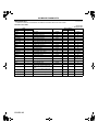
• Differences between the 2006 MY and 2005 MY KOEO/KOER self-test items are shown below.
KOEO/KOER self-test table
EHU010200000104
×: Applicable
—: Not applicable
DTC No.
2006 MY
2005 MY
P0030
←
P0031
←
P0032
←
P0037
←
P0038
←
P0076
←
P0077
←
P0101
←
P0102
←
P0103
←
P0107
←
P0108
←
P0111
←
P0112
←
P0113
←
P0116
—
P0117
←
P0118
←
P0122
←
P0123
←
P0125
←
P0126
←
P0130
←
P0131
←
P0132
←
Condition
Front HO2S heater control circuit problem
Front HO2S heater control circuit low
Front HO2S heater control circuit high
Rear HO2S heater control circuit low
Rear HO2S heater control circuit high
VDI solenoid valve control circuit low
VDI solenoid valve control circuit high
MAF sensor circuit range/performance problem
MAF sensor circuit low input
MAF sensor circuit high input
BARO sensor circuit low input
BARO sensor circuit high input
IAT sensor circuit range/performance problem
IAT sensor circuit low input
IAT sensor circuit high input
Engine coolant temperature circuit range/performance
ECT sensor circuit low input
ECT sensor circuit high input
TP sensor No.1 circuit low input
TP sensor No.1 circuit high input
Insufficient coolant temperature for closed loop fuel control
Insufficient coolant temperature for stable operation
Front HO2S circuit problem
Front HO2S circuit low voltage
Front HO2S circuit high voltage
Test condition
KOEO
KOER
×
×
×
×
×
×
×
×
×
×
×
×
×
×
—
—
×
×
×
×
×
×
×
×
—
—
×
×
×
×
—
—
×
×
×
×
×
×
×
×
—
—
—
—
×
×
×
×
×
×
01–02–9
01–02
ON-BOARD DIAGNOSTIC
DTC No.
2006 MY
2005 MY
P0133
←
P0134
—
P0137
—
P0138
←
P0139
←
P0171
←
P0172
←
P0222
←
P0223
←
P0300
←
P0301
←
P0302
←
P0327
←
P0328
←
P0335
←
P0336
←
P0410
←
P0411
—
P0420
←
P0441
←
P0442
←
P0443
←
P0446
←
P0455
←
P0456
←
P0461
←
P0462
←
P0463
←
P0480
←
P0481
←
P0500
←
P0505
←
P0506
←
P0507
←
P050A
—
P0562
←
P0564
←
P0571
←
P0601
←
P0602
←
P0604
←
P0610
←
P0638
←
P0661
←
P0662
←
P0703
←
P0704
←
P0850
←
P1260
←
P1686
←
P1687
←
P1688
←
P2004
←
01–02–10
Condition
Front HO2S circuit slow response
Front HO2S no activity detected
Rear HO2S circuit low input
Rear HO2S circuit high voltage
Rear HO2S circuit slow response
System too lean
System too rich
TP sensor No.2 circuit low input
TP sensor No.2 circuit high input
Random misfire detected
Front rotor misfire detected
Rear rotor misfire detected
KS circuit low input
KS circuit high input
Eccentric shaft position sensor circuit problem
Eccentric shaft position sensor circuit range/performance problem
Secondary air injection system problem
Secondary air injection system incorrect upstream flow
Catalyst system efficiency below threshold
EVAP system incorrect purge flow
EVAP system leak detected (small leak)
Purge solenoid valve circuit problem
EVAP system vent control circuit problem
EVAP system leak detected (large leak)
EVAP system leak detected (very small leak)
Fuel gauge sender unit circuit range/performance problem
Fuel gauge sender unit (main) circuit low input
Fuel gauge sender unit (main) circuit high input
Cooling fan No.1 control circuit problem
Cooling fan No.2 control circuit problem
VSS circuit problem
Idle air control system problem
Idle air control system RPM lower than expected
Idle air control system RPM higher than expected
Cold start idle air control system performance
System voltage low (KAM)
Cruise control switch input circuit problem
Brake switch input circuit problem
PCM memory check sum error
PCM programming error
PCM random access memory error
PCM vehicle options error
Throttle actuator control circuit range/performance problem
SSV solenoid valve control circuit low
SSV solenoid valve control circuit high
Brake switch input circuit problem
CPP switch input circuit problem
Neutral switch input circuit problem
Immobilizer system problem
Metering oil pump control circuit low flow side problem
Metering oil pump control circuit high flow side problem
Metering oil pump control circuit initial check problem
APV stuck open
Test condition
KOEO
KOER
—
—
—
×
—
—
—
×
—
×
—
×
—
×
×
×
×
×
—
—
—
—
—
—
×
×
×
×
—
—
—
×
—
×
—
—
—
—
—
×
—
×
—
×
—
×
—
×
—
×
—
—
×
×
×
×
×
×
×
×
—
—
—
×
—
—
—
—
—
—
×
×
×
×
×
×
×
×
×
×
×
×
×
×
—
—
×
×
×
×
—
—
—
—
—
—
×
—
—
×
—
×
—
×
×
×
2006 Mazda RX-8 Service Highlights (3409–1U–05J)
ON-BOARD DIAGNOSTIC
DTC No.
2006 MY
2005 MY
P2006
←
P2009
←
P2010
←
P2016
←
P2017
←
P2067
←
P2068
←
P2070
←
P2096
←
P2097
←
P2102
←
P2103
←
P2106
←
P2107
←
P2108
←
P2109
←
P2112
←
P2119
←
P2122
←
P2123
←
P2127
←
P2128
←
P2135
←
P2136
←
P2138
←
P2195
P2196
P2257
P2258
P2259
P2260
P2270
P2271
P2401
P2402
←
←
←
←
←
←
←
←
←
←
P2404
←
P2405
←
P2407
←
P2502
P2503
P2504
←
←
←
Condition
APV motor control driver IC problem
APV motor control circuit low
APV motor control circuit high
APV position sensor circuit low
APV position sensor circuit high
Fuel gauge sender unit (sub) circuit low input
Fuel gauge sender unit (sub) circuit high input
SSV stuck open
Target A/F feedback system too lean
Target A/F feedback system too rich
Drive-by-wire relay control circuit low
Drive-by-wire relay control circuit high
Throttle actuator control system-forced limited power
Throttle actuator control module processor error
Throttle actuator control module performance error
TP sensor minimum stop range/performance problem
Throttle actuator control system range/performance problem
Throttle actuator control throttle body range/performance problem
APP sensor No.1 circuit low input
APP sensor No.1 circuit high input
APP sensor No.2 circuit low input
APP sensor No.2 circuit high input
TP sensor No.1/No.2 voltage correlation problem
TP sensor No.1/No.3 (calculation value in PCM) voltage correlation
problem
TP sensor No.3 (calculation value in PCM)/No.4 (calculation value
in PCM) voltage correlation problem
Front HO2S signal stuck lean
Front HO2S signal stuck rich
AIR pump relay control circuit low
AIR pump relay control circuit high
AIR solenoid valve control circuit low
AIR solenoid valve control circuit high
Rear HO2S signal stuck lean
Rear HO2S signal stuck rich
EVAP system leak detection pump control circuit low
EVAP system leak detection pump control circuit high
EVAP system leak detection pump sense circuit range/performance
problem
EVAP system leak detection pump sense circuit low
EVAP system leak detection pump sense circuit intermittent/erratic
problem
Charging system voltage problem
Charging system voltage low
Charging system voltage high
Test condition
KOEO
KOER
—
—
×
×
×
×
×
×
×
×
×
×
×
×
×
×
—
×
—
×
×
×
×
×
—
—
×
×
—
—
—
—
—
—
×
×
×
×
×
×
×
×
×
×
×
×
×
×
×
×
—
—
×
×
×
×
—
—
×
×
×
×
×
×
×
×
×
×
×
×
—
—
×
×
×
×
—
—
—
×
×
×
End Of Sie
01–02–11
01–02
2006 Mazda RX-8 Service Highlights (3409–1U–05J)
ON-BOARD DIAGNOSTIC
PID/DATA MONITOR AND RECORD
• Differences between the 2006 MY and 2005 MY PID/DATA monitor items are shown below.
PID/DATA monitor item table
EHU010200000105
—: Not applicable
Item
2006 MY
Definition
2005 MY
Unit/Condition
PCM terminal
AC_REQ*1
ACCS
—
Refrigerant pressure switch (high, low)
On/Off
4W
←
A/C relay control signal in PCM
On/Off
5AA
ACSW*2
AIP RLY
ALTF
ALTT V
APP
←
Input signal from A/C switch
On/Off
4W
AIR pump relay control signal in PCM
Generator field coil control signal in PCM
Input voltage from generator
APP
APP from APP sensor No.1
Input voltage from APP sensor No.1
APP from APP sensor No.2
Input voltage from APP sensor No.2
APV motor control signal in PCM
Input voltage from APV position sensor
Target engine speed
On/Off
%
V
%
%
V
%
V
Opening/Closing
V
RPM
4O
2I
2T
5C, 5F
APV
APV_POS
ARPMDES
←
←
←
←
←
←
←
←
←
←
←
B+*2
←
Input voltage from battery
V
5J
BOO
CATT11_DSD
CHRGLP
←
←
←
←
←
COLP
←
BARO
Input voltage from BARO sensor
Input signal from brake switch No.2
Estimated catalyst converter temperature
Generator warning light control signal in PCM
Input signal from refrigerant pressure switch
(medium-pressure)
CPP*3
CPP/PNP
DEI
DTCCNT
←
Input signal from CPP switch
←
←
←
←
←
Input signal from neutral switch
VDI solenoid valve control signal in PCM
DTC count (includes those needing no action)
ECT
Input voltage from ECT sensor
←
APP1
APP2
BARO
kPa
Bar
V
On/Off
psi
5F
5C
3G, 3J
3B
—
5S
On/Off
4P
—
—
On/Off
4Z
On/Off
4F
Drive/Neutral
On/Off
—
°C
°F
V
2O
1W
—
Lambda
—
2B
—
Target lambda
—
—
°
%
°
%
On/Off
On/Off
%
On/Off
FPRR
←
On/Off
4M
FUELPW
←
Throttle valve opening angle
Target throttle valve position
Target throttle valve opening angle
Purge solenoid valve control signal in PCM
Cooling fan relay No.1 control signal in PCM
Cooling fan relay No.2 control signal in PCM
Fuel tank level
Fuel pump relay control signal in PCM
Fuel pump speed control relay control signal in
PCM
Fuel injection duration in PCM
1J, 1M
EVAPCP
FAN1
FAN2
FLI
FP
←
←
←
←
←
←
←
←
2J, 2M
FUELSYS
←
Fuel system loop status
GENVDSD
HTR11
HTR12
IAC
IASV
←
←
←
←
←
Target generator voltage
Front HO2S heater control signal in PCM
Rear HO2S heater control signal in PCM
Throttle actuator control signal in PCM
VFAD solenoid valve control signal in PCM
ms
OL/CL/OL Drive/
OL Fault/CL Fault
V
On/Off
On/Off
%
On/Off
ECT
EQ_RAT11
EQ_RAT11_DS
D*1
ETC_ACT
ETC_DSD
01–02–12
°C
°F
2K
—
2P
5X
5AD
—
5P
—
—
1V
2A
1B, 1C
5Z
Revised 10/2006 (Ref. No. R153/06)
ON-BOARD DIAGNOSTIC
Item
2006 MY
INGEAR
IVS
KNOCKR
2005 MY
←
←
←
←
←
LDP_MON
←
LDP_REF
←
LDP_IDL
←
LDP_SLDV
←
LDP_VSLDV*4
←
LDP_EVAPCP
←
LOAD
LONGFT1
←
←
←
←
←
←
←
←
←
←
←
←
←
←
←
←
←
←
←
←
←
←
←
←
←
←
←
←
←
←
IAT
MAF
MIL
MIL_DIS
MOP_POS
MOP_SW
O2S11
O2S12
PACNTV
PCM_T
RO2FT1
RPM
SC_SET
SCCS
SELTESTDTC
SHRTFT1
SHRTFT12
SPARK-L
SPARK-T
SSV
Test
TIRESIZE
TP
TP REL
TP1
TP2
TPCT
←
VPWR*1
—
VSS
←
*1
*2
*3
*4
Definition
IAT
Input voltage from IAT sensor
In gear
Idle validation
Spark retard value to prevent knocking
Indicates EVAP System leak detection pump
monitoring current
Indicates EVAP System leak detection pump
reference current
Indicates EVAP System leak detection pump idle
current
Indicates EVAP Control system small leak
detection value
Indicates EVAP Control system very small leak
detection value
Indicates EVAP Control system incorrect purge
flow detection value
LOAD
Long term fuel trim
MAF
Input voltage from MAF sensor
MIL control signal in PCM
Distance travelled while MIL is activated
Metering oil pump control status
Input signal from metering oil pump switch
Front HO2S output current
Input voltage from rear HO2S
AIR solenoid valve control signal in PCM
Input voltage from PCM temperature sensor
Target A/F feedback system status
Engine speed
Cruise indicator light control signal in PCM
Input voltage from cruise control switch
DTC count by KOEO/KOER self-test
Short term fuel trim
Target A/F fuel trim
Spark advance (L/F) in PCM
Spark advance (T/F) in PCM
SSV solenoid valve control signal in PCM
Test mode
Tire revolution per mile
Input voltage from TP sensor
Relative TP
TP from TP sensor No.1
Input voltage from TP sensor No.1
TP from TP sensor No.2
Input voltage from TP sensor No.2
Minimum input voltage from TP sensor at throttle
closing
Input voltage from battery (battery positive
voltage)
Vehicle speed
Unit/Condition
°C
°F
V
On/Off
Idle/Off Idle
°
PCM terminal
5K
—
1J, 1M
1T
mA
4D
mA
4D
mA
4D
mA
4D
mA/sec
4D
mA
4D
%
%
g/s
V
On/Off
—
—
5N
km
mile
—
On/Off
mA
V
On/Off
V
—
RPM
On/Off
V
—
%
%
°
°
On/Off
On/Off
rev/mile
V
%
%
V
%
V
KPH
—
—
2V, 2W, 2Y, 2AB
2N
2B
2Q
1O
—
—
—
—
5V
—
—
—
2AA
2AD
1L
—
—
1J, 1M
1J, 1M
1J
1M
V
1J, 1M
V
5J
MPH
—
: 13B-MSP (HIGH POWER)
: 13B-MSP (STANDARD POWER)
: MT model
: California emission regulation applicable model
01–02–13
01–02
ON-BOARD DIAGNOSTIC
End Of Sie
SIMULATION TEST
EHU010200000106
• Differences between the 2006 MY and 2005 MY simulation items are shown below.
Simulation item table
Item
Applicable component
Unit/condition
A/C relay
AIR pump relay
Generator (field coil)
APV motor
Target engine speed
VDI solenoid valve
Target throttle valve opening angle
Purge solenoid valve
Cooling fan relay No.1
Cooling fan relay No.2
Fuel pump relay
Fuel pump speed control relay
Fuel injector (FP1, RP1)
Target generator voltage
Rear HO2S heater
VFAD solenoid valve
On/Off
On/Off
%
opening/closing
RPM
On/Off
°
%
On/Off
On/Off
On/Off
On/Off
%
V
On/Off
On/Off
2006 MY
ACCS
AIP RLY
ALTF
APV
ARPMDES
DEI
ETC_DSD
EVAPCP
FAN1
FAN2
FP
FPRR
FUELPW1
GENVDSD
HTR12
IASV
2005 MY
←
←
←
←
←
←
←
←
←
←
←
←
←
←
←
←
MOP_POS
←
Metering oil pump
PACNTV
SSV
test
←
←
←
Time_DR_LR*1
—
Time_DR_RL*1
—
AIR solenoid valve
SSV solenoid valve
Test mode
Lean-to-rich Delayed Response
Time
Rich-to-lean Delayed Response
Time
Time_SR_LR*1
—
*1
—
Time_SR_RL
*1
: 13B-MSP (HIGH POWER)
End Of Sie
01–02–14
×: Applicable
—: Not applicable
Test condition
KOEO
KOER
×
×
×
×
—
×
×
×
×
×
×
×
×
×
×
×
×
×
×
×
×
×
×
×
—
×
—
×
×
×
×
×
PCM terminal
—
×
×
On/Off
On/Off
On/Off
×
×
×
×
×
×
5AA
4O
2I
3G, 3J
—
1W
—
2P
5X
5AD
5P
4M
2J, 2M
—
2A
5Z
2V, 2W, 2Y,
2AB
1O
1L
—
sec
—
×
—
sec
—
×
—
Lean-to-rich Slow Response Time
sec
—
×
—
Rich-to-lean Slow Response Time
sec
—
×
—
2006 Mazda RX-8 Service Highlights (3409–1U–05J)
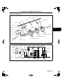
INTAKE-AIR SYSTEM
01–13
INTAKE-AIR SYSTEM
INTAKE-AIR SYSTEM DIAGRAM . . . . . . 01–13–1
INTAKE-AIR SYSTEM HOSE
ROUTING DIAGRAM . . . . . . . . . . . . . . . 01–13–3
End of Toc
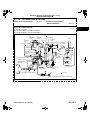
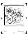
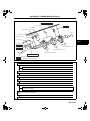
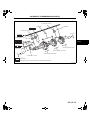
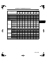
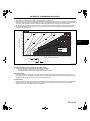
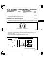
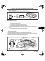
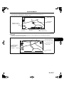
INTAKE-AIR SYSTEM DIAGRAM
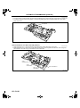
EHU011300000101
Applied VIN (assumed):
JM1 FE173*6# 200001—JM1 FE173*6# 200011
JM1 FE17N*6# 200001—JM1 FE17N*6# 200011
TO CHARCOAL CANISTER
AIR
SOLENOID
VALVE
VDI
SOLENOID
VALVE
SSV
SOLENOID
VALVE
CATCH TANK
VFAD
THROTTLE
VALVE
C
A
B
TO METERING OIL NOZZLE
AIR CLEANER
TO FUEL TANK
VACUUM
CHAMBER
CHECK
VALVE
SSV
VDI ACTUATOR
TO REAR
PRIMARY/SECONDARY
PORTS
VDI VALVE
TO POWER
BRAKE UNIT
D
AUXILIARY
PORT
/APV
B
SSV ACTUATOR
FRONT
HOUSING
PRIMARY PORT
INTERMEDIATE
HOUSING
VACUUM
CHAMBER
VFAD
ACTUATOR
VFAD
SOLENOID
VALVE
C
D
CHECK VALVE
APV
MOTOR
13B-MSP
(HIGH POWER)
13B-MSP
(HIGH POWER)
SECONDARY
PORT
A
JET AIR FUEL MIXING NOZZLE
TO PCM
(ILLUSTRATION SHOWS 13B-MSP (HIGH POWER))
CHU0113W001
Added 4/2006 (Ref. No. R027/06)
01–13–1
01–13
2006 Mazda RX-8 Service Highlights (3409–1U–05J)
INTAKE-AIR SYSTEM
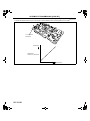
Applied VIN (assumed):
JM1 FE173*6# 200012—
JM1 FE17N*6# 200012—End Of Sie
TO CHARCOAL CANISTER
AIR SOLENOID
VALVE
VDI SOLENOID
VALVE
SSV
SOLENOID
VALVE
CATCH TANK
C
A
B
TO METERING OIL NOZZLE
AIR CLEANER
TO FUEL TANK
VACUUM
CHAMBER
VFAD
THROTTLE
VALVE
CHECK
VALVE
SSV
VDI ACTUATOR
TO REAR
PRIMARY/SECONDARY
PORTS
VDI VALVE
TO POWER
BRAKE UNIT
AUXILIARY
PORT/APV
B
SSV ACTUATOR
D
FRONT
HOUSING
PRIMARY PORT
INTERMEDIATE
HOUSING
VACUUM
CHAMBER
VFAD
ACTUATOR
VFAD
SOLENOID
VALVE
C
D
CHECK VALVE
APV
MOTOR
13B-MSP (HIGH
POWER)
13B-MSP (HIGH
POWER)
SECONDARY PORT
A
JET AIR FUEL MIXING NOZZLE
TO PCM
(ILLUSTRATION SHOWS 13B-MSP (HIGH POWER))
EHU113ZS4A02
01–13–2
Added 4/2006 (Ref. No. R027/06)
2006 Mazda RX-8 Service Highlights (3409–1U–05J)
INTAKE-AIR SYSTEM
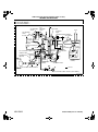
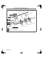
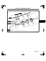
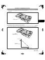
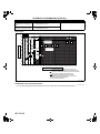
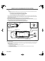
INTAKE-AIR SYSTEM HOSE ROUTING DIAGRAM
EHU011300000102
Applied VIN (assumed):
JM1 FE173*6# 200001—JM1 FE173*6# 200011
JM1 FE17N*6# 200001—JM1 FE17N*6# 200011
VDI ACTUATOR
SSV ACTUATOR
01–13
AIR SOLENOID
VALVE
INTAKE MANIFOLD
METERING
OIL NOZZLE
EXTENSION MANIFOLD
(UPPER)
PURGE
SOLENOID VALVE
AIR PUMP
METERING
OIL NOZZLE
VACUUM
CHAMBER
ONE-WAY
CHECK VALVE
SSV SOLENOID
VALVE
AIR CONTROL VALVE
EXHAUST MANIFOLD
VDI SOLENOID VALVE
ONE-WAY CHECK VALVE
(13B-MSP (HIGH POWER))
VFAD SOLENOID VALVE
(13B-MSP (HIGH POWER))
VACUUM CHAMBER
(13B-MSP (HIGH POWER))
VFAD ACTUATOR
(13B-MSP (HIGH POWER))
(ILLUSTRATION SHOWS 13B-MSP (HIGH POWER))
CHU0113W002
Added 4/2006 (Ref. No. R027/06)
01–13–3
2006 Mazda RX-8 Service Highlights (3409–1U–05J)
INTAKE-AIR SYSTEM
Applied VIN (assumed):
JM1 FE173*6# 200012—
JM1 FE17N*6# 200012—End Of Sie
VDI ACTUATOR
SSV ACTUATOR
AIR SOLENOID
VALVE
INTAKE MANIFOLD
METERING OIL
NOZZLE
EXTENSION MANIFOLD
(UPPER)
PURGE SOLENOID
VALVE
AIR PUMP
METERING
OIL NOZZLE
VACUUM
CHAMBER
ONE-WAY
CHECK VALVE
SSV SOLENOID
VALVE
AIR CONTROL VALVE
EXHAUST MANIFOLD
VDI SOLENOID VALVE
ONE-WAY CHECK VALVE
(13B-MSP (HIGH POWER))
VFAD SOLENOID VALVE (13B-MSP
(HIGH POWER))
VACUUM CHAMBER (13B-MSP
(HIGH POWER))
VFAD ACTUATOR (13B-MSP
(HIGH POWER))
(ILLUSTRATION SHOWS 13B-MSP (HIGH POWER))
EHU113ZS4A01
01–13–4
Added 4/2006 (Ref. No. R027/06)
TRANSMISSION/TRANSAXLE
05
SECTION
Toc
of SCT . . . . . . . . . . . . . . . . . . 05-00
OUTLINE
ON-BOARD DIAGNOSTIC
[SJ6A-EL] . . . . . . . . . . . . . . . . 05-02
AUTOMATIC
TRANSMISSION
[SJ6A-EL] . . . . . . . . . . . . . . . 05-13
AUTOMATIC TRANSMISSION
SHIFT MECHANISM . . . . . . . 05-14
Toc of SCT
05–00
OUTLINE
TRANSMISSION/TRANSAXLE
ABBREVIATIONS. . . . . . . . . . . . . . . . . . 05–00–1
TRANSMISSION/TRANSAXLE
FEATURES . . . . . . . . . . . . . . . . . . . . . . . 05–00–1
05–00
TRANSMISSION/TRANSAXLE
SPECIFICATIONS . . . . . . . . . . . . . . . . . 05–00–2
Automatic Transmission . . . . . . . . . . . . 05–00–2
End of Toc
TRANSMISSION/TRANSAXLE ABBREVIATIONS
AAS
ATF
AT
CAN
CPU
DC
EC-AT
PPF
1GR
2GR
3GR
4GR
5GR
6GR
EHU050000000101
Active Adaptive Shift
Automatic Transmission Fluid
Automatic Transmission
Controller Area Network
Central Processing Unit
Drive Cycle
Electronically Controlled Automatic Transmission
Power Plant Frame
First Gear
Second Gear
Third Gear
Fourth Gear
Fifth Gear
Sixth Gear
End Of Sie
TRANSMISSION/TRANSAXLE FEATURES
6-SPEED AT [SJ6A-EL]
Improved fuel economy
Improved marketability
Superior shift quality
Improved driveability
EHU050000000108
• Six-speed SJ6A-EL automatic transmission has been adopted.
• Six-speed SJ6A-EL automatic transmission has been adopted.
• The Sport AT has been adopted. With this feature up and downshifting can be performed with
either the shift control switch on the steering wheel or with the one-touch operation of the
selector lever.
• A 5-6 shift inhibit control has been adopted for rapid engine warming.
• Torque reduction control and line pressure control has been adopted.
• Shift learning control has been adopted.
• To improve drivetrain rigidity, a closed section power plant frame (PPF) has been adopted.
• A control feature for climbing/descending hills has been adopted, improving driveability when
climbing/descending.
End Of Sie
05–00–1
OUTLINE
TRANSMISSION/TRANSAXLE SPECIFICATIONS
EHU050000000106
Automatic Transmission
Item
Transmission type
Gear ratio
1GR
2GR
3GR
4GR
5GR
6GR
Reverse
Type
ATF
Capacity (Approx. quantity)
(L {US qt, lmp qt})
Torque converter stall torque ratio
Low clutch
High clutch
Reverse clutch
2-4 brake
Low and reverse brake
C1 clutch
Hydraulic system
C2 clutch
(Number of drive/driven plates)
C3 clutch
C4 clutch
B1 brake
B2 brake
B3 brake
B4 brake
Sun gear
Pinion gear
Pinion gear (inner)
Front planetary gear (Number of teeth)
Pinion gear (outer)
Internal gear
Ring gear
Sun gear
Middle planetary gear (Number of teeth) Pinion gear
Ring gear
Sun gear
Pinion gear
Rear planetary gear (Number of teeth)
Internal gear
Ring gear
End Of Sie
05–00–2
2005MY RX-8
RC4A-EL
2.785
1.545
1.000
0.694
—
—
2.272
ATF M-III or
equivalent
(e.g. Dexron®III)
←
←
←
←
←
—
—
←
2006MY RX-8
SJ6A-EL
3.538
2.060
1.404
1.000
0.713
0.582
3.168
←
JWS3309
8.7 {9.2, 7.7}
←
7.9 {8.4, 7.0}
2.04:1
5/5
6/6
2/2
4/4
4/5
—
—
—
—
—
—
—
—
33
21
—
—
75
—
—
—
—
42
17
75
—
←
←
←
←
←
←
—
—
—
—
—
—
—
—
←
←
—
—
←
—
—
—
—
←
←
←
—
1.85:1
—
—
—
—
—
4/4
5/5
4/3
4/4
3/3
4/3
4/4
5/4
←
—
19
18
—
75
26
20
66
26
20
—
66
ON-BOARD DIAGNOSTIC [SJ6A-EL]
05–02
ON-BOARD DIAGNOSTIC [SJ6A-EL]
ON-BOARD DIAGNOSTIC (OBD)
SYSTEM OUTLINE [SJ6A-EL] . . . . . . . 05–02–1
ON-BOARD DIAGNOSTIC (OBD)
SYSTEM BLOCK DIAGRAM
[SJ6A-EL] . . . . . . . . . . . . . . . . . . . . . . . 05–02–1
MALFUNCTION DETECTION FUNCTION
[SJ6A-EL] . . . . . . . . . . . . . . . . . . . . . . . 05–02–2
Malfunction Detection Function . . . . . . 05–02–2
DTC Table . . . . . . . . . . . . . . . . . . . . . . 05–02–2
MEMORY FUNCTION [SJ6A-EL] . . . . . . 05–02–3
MALFUNCTION INDICATION FUNCTION
[SJ6A-EL] . . . . . . . . . . . . . . . . . . . . . . . . 05–02–3
FAIL-SAFE FUNCTION [SJ6A-EL] . . . . . 05–02–3
Emergency Mode . . . . . . . . . . . . . . . . . 05–02–7
PARAMETER IDENTIFICATION (PID)
DATA MONITORING FUNCTION
[SJ6A-EL] . . . . . . . . . . . . . . . . . . . . . . . . 05–02–7
Monitor Item Table. . . . . . . . . . . . . . . . . 05–02–7
SIMULATION FUNCTION
[SJ6A-EL] . . . . . . . . . . . . . . . . . . . . . . . . 05–02–8
Simulation Item Table . . . . . . . . . . . . . . 05–02–8
DLC-2 OUTLINE [SJ6A-EL]. . . . . . . . . . . 05–02–8
End of Toc
ON-BOARD DIAGNOSTIC (OBD) SYSTEM OUTLINE [SJ6A-EL]
EHU050200000101
• The OBD system has the following functions:
— Malfunction detection function: detects malfunctions of the input/output devices and system components of
the AT.
— Fail-safe function: controls the output device function and input value of the sensors/switches to ensure
minimum vehicle drivability when a failure is detected.
— Memory function: stores the DTC when a failure is detected.
— PID data monitoring function: monitors the input/output signal and calculated value of the TCM and sends
the monitoring data to the scan tool.
— Simulation function: Allows override operation of simulation items for input/output system parts preset in the
TCM.
End Of Sie
ON-BOARD DIAGNOSTIC (OBD) SYSTEM BLOCK DIAGRAM [SJ6A-EL]
EHU050200000102
TCM
INSTRUMENT
CLUSTER
OBD SYSTEM
MEMORY
FUNCTION
MALFUNCTION
DETECTION
FUNCTION
PID DATA
MONITORING
FUNCTION
MALFUNCTION
INDICATION
FUNCTION
CAN
SERIAL
COMMUNICATION
CAN
SIMULATION
FUNCTION
AT WARNING
LIGHT
MIL
DLC-2
WDS OR
EQUIVALENT
FAIL-SAFE
FUNCTION
INPUT
PARTS
PCM (CAN)
TRANSAXLE CONTROL SYSTEM
OUTPUT
PARTS
E5U502ZS5001
End Of Sie
05–02–1
05–02
ON-BOARD DIAGNOSTIC [SJ6A-EL]
MALFUNCTION DETECTION FUNCTION [SJ6A-EL]
EHU050200000103
Malfunction Detection Function
• In the malfunction detection function, the TCM detects malfunctions in the automatic transmission while driving.
• When vehicle driving conditions correspond with a preset malfunction detection condition, the TCM determines
that the automatic transmission has a malfunction and stores the corresponding DTC.
• When a malfunction is detected, stored DTCs can be retrieved using the WDS or equivalent connected to the
DLC-2.
DTC Table
X: Available
–: N/A
DTC No.
Condition
MIL
P0601
P0603
P0604
P0707
P0708
P0711
Flash ROM malfunction
EEPROM malfunction
RAM malfunction
Transmission range (TR) switch circuit low input (short to ground)
Transmission range (TR) switch circuit high input (open circuit)
Transmission fluid temperature (TFT) sensor malfunction (stuck)
Transmission fluid temperature (TFT) sensor circuit malfunction (short to
ground)
Transmission fluid temperature (TFT) sensor circuit malfunction (short to
power/open circuit)
Turbine sensor circuit malfunction (open circuit/short circuit)
Vehicle speed sensor (VSS) circuit malfunction (open circuit/short circuit)
Shift solenoid A malfunction (stuck off)
Shift solenoid A malfunction (stuck on)
Shift solenoid B malfunction (stuck off)
Shift solenoid B malfunction (stuck on)
Shift solenoid C malfunction (stuck off)
Shift solenoid C malfunction (stuck on)
Shift solenoid D malfunction (stuck off)
Shift solenoid G malfunction (stuck on)
1-2 shift valve malfunction
Reverse sequence valve malfunction
Manual switch/up switch/down switch circuit malfunction (open circuit/short
circuit)
Steering shift switch circuit malfunction (open circuit/short to ground)
TCM B+ low (less than 9 V)
TCM B+ low (less than 11 V)
Line pressure control solenoid range/performance (stuck)
Line pressure control solenoid circuit malfunction (short to ground/open circuit)
Line pressure control solenoid circuit malfunction (short to power)
Shift solenoid F range/performance (stuck)
Shift solenoid F circuit malfunction (short to ground/open circuit)
Shift solenoid F circuit malfunction (short to power)
Shift solenoid A circuit malfunction (short to ground)
Shift solenoid A circuit malfunction (short to power/open circuit)
Shift solenoid B circuit malfunction (short to ground)
Shift solenoid B circuit malfunction (short to power/open circuit)
Shift solenoid C circuit malfunction (short to ground)
Shift solenoid C circuit malfunction (short to power/open circuit)
Shift solenoid D circuit malfunction (short to ground)
Shift solenoid D circuit malfunction (short to power/open circuit)
Shift solenoid E circuit malfunction (short to ground)
Shift solenoid E circuit malfunction (short to power/open circuit)
X
X
X
X
X
X
AT
warning
light
X
X
X
X
X
X
X
P0712
P0713
P0717
P0722
P0751
P0752
P0756
P0757
P0761
P0762
P0766
P0781
P0813
P0819
P0826
P0882
P0883
P0961
P0962
P0963
P0969
P0970
P0971
P0973
P0974
P0976
P0977
P0979
P0980
P0982
P0983
P0985
P0986
05–02–2
DC
Memory
function
1
1
1
1
2
2
X
X
X
X
X
X
X
1
X
X
X
1
X
X
X
X
X
X
X
X
X
X
X
X
X
X
X
X
X
X
X
X
X
X
X
X
X
1
1
2
2
2
2
2
2
2
2
2
2
X
X
X
X
X
X
X
X
X
X
X
X
–
X
1
X
X
–
–
X
X
X
X
X
X
X
X
X
X
X
X
X
X
X
X
X
X
X
X
X
X
X
X
X
X
X
X
X
X
X
X
X
X
X
1
1
1
1
1
1
1
1
1
1
1
1
1
1
1
1
1
1
1
X
X
X
X
X
X
X
X
X
X
X
X
X
X
X
X
X
X
X
ON-BOARD DIAGNOSTIC [SJ6A-EL]
DTC No.
P2719
P2720
P2721
P2757
P2758
P2762
P2763
P2764
U0073
U0100
U0121
Condition
MIL
Shift solenoid G range/performance (stuck)
Shift solenoid G circuit malfunction (short to ground/open circuit)
Shift solenoid G circuit malfunction (short to power)
Torque converter clutch (TCC) stuck off
Torque converter clutch (TCC) stuck on
TCC control solenoid range/performance (stuck)
TCC control solenoid circuit malfunction (short to power)
TCC control solenoid circuit malfunction (short to ground/open circuit)
CAN BUS OFF
TCM cannot receive any signals from PCM
TCM cannot receive any signals from ABS HU/CM or DSC HU/CM
X
X
X
X
X
X
X
X
X
X
X
AT
warning
light
X
X
X
X
X
X
X
X
X
X
X
DC
Memory
function
1
1
1
2
2
1
1
1
1
1
1
X
X
X
X
X
X
X
X
X
X
X
MIL: Malfunction Indicator Lamp
DC: Drive Cycle
05–02
End Of Sie
MEMORY FUNCTION [SJ6A-EL]
EHU050200000104
• The memory function stores malfunction information detected in the malfunction detection function. Once
malfunction information is stored, the memory will not be cleared even when the ignition switch is turned off
(LOCK position) or the malfunction is repaired.
• The stored memory (malfunction information) can be cleared using the WDS or equivalent, or by disconnecting
the negative battery cable.
End Of Sie
MALFUNCTION INDICATION FUNCTION [SJ6A-EL]
EHU050200000105
• The malfunction indication function illuminates the MIL or AT warning light when the malfunction detection
function determines there is a malfunction.
End Of Sie
FAIL-SAFE FUNCTION [SJ6A-EL]
EHU050200000106
• In the fail-safe function, minimum vehicle drivability is obtained by changing the signals that are determined to
be malfunctions by the malfunction detection function to the preset values, and limiting TCM control.
DTC
No.
On-board diagnostic
function
Detection condition
P0601
Flash ROM malfunction
• Flash ROM (in TCM) internal circuit
malfunction is detected.
P0603
EEPROM malfunction
• Different numeric values for
EEPRROM and RAM (in TCM) are
detected.
P0604
P0707
P0708
P0711
RAM malfunction
• RAM (in TCM) read/write error is
detected.
Transmission range (TR)
switch circuit low input
(short to ground)
Transmission range (TR)
switch circuit high input
(open circuit)
• TR switch position voltage input to
TCM is less than 0.127 V when
ignition switch is at ON position.
• Vehicle speed is 30 km/h {18.6 mph}
or more, and no range signal is input
from the TR switch.
Transmission fluid
temperature (TFT) sensor
malfunction (stuck)
• Change in ATF temperature cannot be
detected for 10 min or more when
driving in D range.
Fail-safe
•
•
•
•
•
Emergency mode
Inhibits self learning control
Inhibits driver adaptive shift control
Inhibits TCC control
Inhibits slip control
N/A
•
•
•
•
•
•
•
•
•
•
•
•
•
Emergency mode
Inhibits self learning control
Inhibits driver adaptive shift control
Inhibits TCC control
Inhibits slip control
D range is determined when there is no
TR switch signal input.
Inhibits slope mode control
D range is determined when there is no
TR switch signal input.
Inhibits slope mode control
Fixes ATF temperature value at 80 °C
{176 °F}
Inhibits slope mode control
Inhibits self learning control
Inhibits slip control
05–02–3
ON-BOARD DIAGNOSTIC [SJ6A-EL]
DTC
No.
On-board diagnostic
function
P0712
Transmission fluid
temperature (TFT) sensor
circuit malfunction (short to
ground)
• TCM detects ATF temperature of 200
°C {392 °F} or more.
P0713
Transmission fluid
temperature (TFT) sensor
circuit malfunction (short to
power/open circuit)
• TCM detects ATF temperature of less
than -43 °C {-45.4 °F} when engine is
warmed-up and running.
P0717
Turbine sensor circuit
malfunction (open circuit/
short circuit)
• Turbine speed signal is not input during
vehicle speed signal 12 pulse period
when driving in D range.
P0722
Vehicle speed sensor
(VSS) circuit malfunction
(open circuit/short circuit)
• Vehicle speed signal is not input during
turbine speed signal 12 pulse period
when driving in D range.
P0751
Shift solenoid A
malfunction (stuck off)
P0752
Shift solenoid A
malfunction (stuck on)
P0756
Shift solenoid B
malfunction (stuck off)
P0757
Shift solenoid B
malfunction (stuck on)
P0761
Shift solenoid C
malfunction (stuck off)
P0762
Shift solenoid C
malfunction (stuck on)
Shift solenoid D
malfunction (stuck off)
P0766
Shift solenoid G
malfunction (stuck on)
P0781
1-2 shift valve malfunction
P0813
Reverse sequence valve
malfunction
Detection condition
• TCM detects that shift solenoid A does
not change from off when engine is
running
• TCM detects that shift solenoid A does
not change from on when engine is
running
• TCM detects that shift solenoid B does
not change from off when engine is
running
• TCM detects that shift solenoid B does
not change from on when engine is
running
• TMC detects that shift solenoid C does
not change from off when engine is
running
• TMC detects that shift solenoid C doe
not change from on when engine is
running
• TCM detects that shift solenoid D does
not change from off when engine is
running
• TCM detects that shift solenoid G does
not change from on when engine is
running
• TCM detects 1–2 shift valve
malfunction.
• TCM detects reverse sequence valve
malfunction.
M range switch circuit malfunction
• M range switch remains on for 2 s or
more except in D range.
P0819
Manual switch/up switch/
down switch circuit
malfunction (open circuit/
short circuit)
05–02–4
Fail-safe
• Fixes ATF temperature value at 80 °C
{176 °F}
• Inhibits slope mode control
• Inhibits self learning control
• Inhibits slip control
• Fixes ATF temperature value at 80 °C
{176 °F}
• Inhibits slope mode control
• Inhibits self learning control
• Inhibits slip control
• Substitutes vehicle speed signal for
turbine speed signal.
• Inhibits 5GR and 6GR
• Inhibits self learning control
• Inhibits driver adaptive shift control
• Inhibits slip control
• Substitutes turbine speed signal for
vehicle speed signal.
• Inhibits 5GR and 6GR
• Inhibits self learning control
• Inhibits driver adaptive shift control
• Inhibits slip control
• Inhibits 4GR, 5GR and 6GR
• Inhibits 1GR and 2GR (manual mode)
N/A
N/A
N/A
N/A
• Inhibits 4GR, 5GR and 6GR
• Inhibits 4GR, 5GR and 6GR
• Inhibits 4GR, 5GR and 6GR
• Inhibits 4GR, 5GR and 6GR
• Inhibits 1GR and 2GR (manual mode)
• Inhibits 6GR
• Inhibits manual mode control
Up switch or down switch circuit
malfunction
• When all of the following conditions are
met:
— M range switch off.
— Except D range
— Up or down switch remains on for 10
s or more.
• Inhibits manual mode control using
selector lever
ON-BOARD DIAGNOSTIC [SJ6A-EL]
DTC
No.
On-board diagnostic
function
Steering shift switch circuit
malfunction (open circuit/
short to ground)
Detection condition
Fail-safe
• TCM detects short circuit or short to
ground in steering shift switch circuit
when engine is running.
• Inhibits manual mode control
P0882
TCM B+ low (less than 9
V)
• Voltage of less than 9 V detected at
TCM terminals 1AD when engine is
running.
•
•
•
•
•
P0883
TCM B+ low (less than 11
V)
• Voltage of less than 11 V detected at
TCM terminals 1AD when engine is
running.
• Inhibits self learning control
P0961
Line pressure control
solenoid range/
performance (stuck)
• Feedback current corresponding to
solenoid current command value is
irregular when engine is running.
P0962
Line pressure control
solenoid circuit malfunction
(short to ground/open
circuit)
P0963
Line pressure control
solenoid circuit malfunction
(short to power)
P0969
Shift solenoid F range/
performance (stuck)
• Feedback current corresponding to
solenoid current command value is
irregular when engine is running.
P0970
Shift solenoid F circuit
malfunction (short to
ground/open circuit)
• Open or short circuit in shift solenoid F
signal system (while TCM monitors
solenoid output voltage, the voltage
that differs from the signal output by
CPU in TCM is detected).
P0971
Shift solenoid F circuit
malfunction (short to
power)
• Short circuit in shift solenoid F signal
system (while TCM monitors solenoid
output voltage, the voltage that differs
from the signal output by CPU in TCM
is detected).
P0973
Shift solenoid A circuit
malfunction (short to
ground)
P0974
Shift solenoid A circuit
malfunction (short to
power/open circuit)
P0976
Shift solenoid B circuit
malfunction (short to
ground)
P0977
Shift solenoid B circuit
malfunction (short to
power/open circuit)
P0826
• Open or short circuit in line pressure
control solenoid signal system (while
TCM monitors solenoid output voltage,
the voltage that differs from the signal
output by CPU in TCM is detected).
• Short circuit in line pressure control
solenoid signal system (while TCM
monitors solenoid output voltage, the
voltage that differs from the signal
output by CPU in TCM is detected).
• Short to ground in shift solenoid A
signal system (while TCM monitors
solenoid output voltage, the voltage
that differs from the signal output by
CPU in TCM is detected).
• Open or short circuit in shift solenoid A
signal system (while TCM monitors
solenoid output voltage, the voltage
that differs from the signal output by
CPU in TCM is detected).
• Short to ground in shift solenoid B
signal system (while TCM monitors
solenoid output voltage, the voltage
that differs from the signal output by
CPU in TCM is detected).
• Open or short circuit in shift solenoid B
signal system (while TCM monitors
solenoid output voltage, the voltage
that differs from the signal output by
CPU in TCM is detected).
•
•
•
•
•
•
•
•
•
•
•
•
•
•
•
•
•
•
•
•
•
•
•
•
•
•
•
•
•
•
•
•
•
•
•
•
•
•
•
•
•
•
•
•
•
•
•
•
•
•
•
Emergency mode
Inhibits self learning control
Inhibits driver adaptive shift control
Inhibits TCC control
Inhibits slip control
Emergency mode
Inhibits self learning control
Inhibits driver adaptive shift control
Inhibits TCC control
Inhibits slip control
Emergency mode
Inhibits self learning control
Inhibits driver adaptive shift control
Inhibits TCC control
Inhibits slip control
Emergency mode
Inhibits self learning control
Inhibits driver adaptive shift control
Inhibits TCC control
Inhibits slip control
Emergency mode
Inhibits self learning control
Inhibits driver adaptive shift control
Inhibits TCC control
Inhibits slip control
Emergency mode
Inhibits self learning control
Inhibits driver adaptive shift control
Inhibits TCC control
Inhibits slip control
Emergency mode
Inhibits N—D shift pressure control
Inhibits self learning control
Inhibits driver adaptive shift control
Inhibits TCC control
Inhibits slip control
Emergency mode
Inhibits self learning control
Inhibits driver adaptive shift control
Inhibits TCC control
Inhibits slip control
Emergency mode
Inhibits self learning control
Inhibits driver adaptive shift control
Inhibits TCC control
Inhibits slip control
Emergency mode
Inhibits self learning control
Inhibits driver adaptive shift control
Inhibits TCC control
Inhibits slip control
Emergency mode
Inhibits self learning control
Inhibits driver adaptive shift control
Inhibits TCC control
Inhibits slip control
05–02–5
05–02
ON-BOARD DIAGNOSTIC [SJ6A-EL]
DTC
No.
On-board diagnostic
function
P0979
Shift solenoid C circuit
malfunction (short to
ground)
P0980
Shift solenoid C circuit
malfunction (short to
power/open circuit)
P0982
Shift solenoid D circuit
malfunction (short to
ground)
P0983
Shift solenoid D circuit
malfunction (short to
power/open circuit)
P0985
Shift solenoid E circuit
malfunction (short to
ground)
P0986
Shift solenoid E circuit
malfunction (short to
power/open circuit)
P2719
Shift solenoid G range/
performance (stuck)
P2720
Shift solenoid G circuit
malfunction (short to
ground/open circuit)
P2721
Shift solenoid G circuit
malfunction (short to
power)
P2757
Torque converter clutch
(TCC) stuck off
P2758
Torque converter clutch
(TCC) stuck on
P2762
TCC control solenoid
range/performance (stuck)
P2763
TCC control solenoid
circuit malfunction (short to
power)
P2764
TCC control solenoid
circuit malfunction (short to
ground/open circuit)
05–02–6
Detection condition
• Short to ground in shift solenoid C
signal system (while TCM monitors
solenoid output voltage, the voltage
that differs from the signal output by
CPU in TCM is detected).
• Open or short circuit in shift solenoid C
signal system (while TCM monitors
solenoid output voltage, the voltage
that differs from the signal output by
CPU in TCM is detected).
• Short to ground in shift solenoid D
signal system (while TCM monitors
solenoid output voltage, the voltage
that differs from the signal output by
CPU in TCM is detected).
• Open or short circuit in shift solenoid D
signal system (while TCM monitors
solenoid output voltage, the voltage
that differs from the signal output by
CPU in TCM is detected).
• Short to ground in shift solenoid E
signal system (while TCM monitors
solenoid output voltage, the voltage
that differs from the signal output by
CPU in TCM is detected).
• Open or short circuit in shift solenoid E
signal system (while TCM monitors
solenoid output voltage, the voltage
that differs from the signal output by
CPU in TCM is detected).
• Feedback current corresponding to
solenoid current command value is
irregular when engine is running.
• Open or short circuit in shift solenoid G
signal system (while TCM monitors
solenoid output voltage, the voltage
that differs from the signal output by
CPU in TCM is detected).
• Short circuit in shift solenoid G signal
system (while TCM monitors solenoid
output voltage, the voltage that differs
from the signal output by CPU in TCM
is detected).
• TCM detects that TCC control solenoid
does not change from off when engine
is running
• TCM detects that TCC control solenoid
does not change from on when engine
is running
• Feedback current corresponding to
solenoid current command value is
irregular when engine is running.
• Short circuit in TCC control solenoid
signal system (while TCM monitors
solenoid output voltage, the voltage
that differs from the signal output by
CPU in TCM is detected).
• Open or short circuit in TCC control
solenoid signal system (while TCM
monitors solenoid output voltage, the
voltage that differs from the signal
output by CPU in TCM is detected).
Fail-safe
•
•
•
•
•
•
•
•
•
•
•
•
•
•
•
•
•
•
•
•
•
•
•
•
•
•
•
•
•
•
•
•
•
•
•
•
•
•
•
•
•
•
•
•
•
Emergency mode
Inhibits self learning control
Inhibits driver adaptive shift control
Inhibits TCC control
Inhibits slip control
Emergency mode
Inhibits self learning control
Inhibits driver adaptive shift control
Inhibits TCC control
Inhibits slip control
Emergency mode
Inhibits self learning control
Inhibits driver adaptive shift control
Inhibits TCC control
Inhibits slip control
Emergency mode
Inhibits self learning control
Inhibits driver adaptive shift control
Inhibits TCC control
Inhibits slip control
Emergency mode
Inhibits self learning control
Inhibits driver adaptive shift control
Inhibits TCC control
Inhibits slip control
Emergency mode
Inhibits self learning control
Inhibits driver adaptive shift control
Inhibits TCC control
Inhibits slip control
Emergency mode
Inhibits self learning control
Inhibits driver adaptive shift control
Inhibits TCC control
Inhibits slip control
Emergency mode
Inhibits self learning control
Inhibits driver adaptive shift control
Inhibits TCC control
Inhibits slip control
Emergency mode
Inhibits self learning control
Inhibits driver adaptive shift control
Inhibits TCC control
Inhibits slip control
N/A
• Inhibits acceleration from 2GR
• Inhibits acceleration from 2GR
• Inhibits TCC control
• Inhibits slip control
• Inhibits acceleration from 2GR
• Inhibits TCC control
• Inhibits slip control
• Inhibits acceleration from 2GR
• Inhibits TCC control
• Inhibits slip control
ON-BOARD DIAGNOSTIC [SJ6A-EL]
DTC
No.
On-board diagnostic
function
Detection condition
Fail-safe
U0073
CAN BUS OFF
• Bus off error is detected.
U0100
TCM cannot receive any
signals from PCM
• Communication error is detected
between TCM and PCM.
U0121
TCM cannot receive any
signals from ABS HU/CM
or DSC HU/CM
• Communication error is detected
between TCM and ABS HU/CM or
DSC HU/CM.
•
•
•
•
•
•
•
•
•
•
•
•
•
Inhibits self learning control
Inhibits driver adaptive shift control
Inhibits TCC control
Inhibits 5GR, 6GR
Inhibits slip control
Inhibits self learning control
Inhibits driver adaptive shift control
Inhibits TCC control
Inhibits 5GR, 6GR
Inhibits slip control
Inhibits self learning control
Inhibits TCC control
Inhibits slip control
Emergency Mode
• Emergency mode shifts as follows when in D range or R position.
05–02
Selector lever position
Condition
D range
Normal shifting
When there is any malfunction in shift
solenoids A, B, C, D, E, F, G, line
pressure, or TCC control solenoid
1GR
2GR
3GR
4GR
5GR
4GR
6GR
R
position
Reverse
Reverse
End Of Sie
PARAMETER IDENTIFICATION (PID) DATA MONITORING FUNCTION [SJ6A-EL]
EHU050200000107
• The PID mode allows access to certain data values, analog and digital input and output, calculations and
system state information.
Monitor Item Table
Display on the tester
BOO TCM
DTCCNT
DWN SW
ECT TCM
FDPDTC
GEAR_RA
GEAR_SEL
LPS
MNL SW
OSS
PNP_TCM
RPM TCM
SS SWSS SW+
SSA
SSB
SSC
SSD
SSE
SSF
SSG
TCCC
TFT
TFTV
THOP
TR
Definition
Brake switch
DTC count (includes those needing no action)
Down switch
Engine coolant temperature
Freeze frame data
Gear ratio
Calculated gear range in TCM
Line pressure control solenoid
M range switch
Output shaft speed
Park/Neutral
Engine speed
Steering shift switch (shift down)
Steering shift switch (shift up)
Shift solenoid A
Shift solenoid B
Shift solenoid C
Shift solenoid D
Shift solenoid E
Shift solenoid F
Shift solenoid G
TCC control solenoid
ATF temperature
ATF temperature signal voltage
Throttle position
TR switch
Unit/Condition
On/Off
N/A
On/Off
°C
N/A
N/A
1/2/3/4/5/6
A
On/Off
RPM
Drive/Neutral
RPM
On/Off
On/Off
On/Off
On/Off
On/Off
On/Off
On/Off
A
A
A
°C
V
%
R/N/D/P
TCM terminal
N/A
N/A
2F
N/A
N/A
N/A
N/A
1E, 1R
2G
2C, 2D
2K, 2M, 2N, 2O
N/A
2AB, 2AF
2AB, 2AF
1AF
1AB
1AA
1S
1V
1O, 1Z
1L, 1Y
1D, 1Q
1J, 1M
1J, 1M
N/A
2K, 2M, 2N, 2O
05–02–7
ON-BOARD DIAGNOSTIC [SJ6A-EL]
Display on the tester
TRD
TRR
TSS
UP SW
VPWR
VSS
Definition
TR switch [D range]
TR switch [R position]
Input/turbine speed sensor
Up switch
Battery voltage
Vehicle speed
Unit/Condition
On/Off
On/Off
RPM
On/Off
V
KPH
TCM terminal
2K
2M
2A, 2B
2J
1AD
2C, 2D
End Of Sie
SIMULATION FUNCTION [SJ6A-EL]
EHU050200000108
• By using the WDS or equivalent, simulation items for input/output parts preset in the TCM can be optionally
selected and operated regardless of TCM control conditions.
Simulation Item Table
X: Available
Simulation
item
LPS
SSA
SSB
SSC
SSD
SSE
SSF
SSG
TCCC
Applicable component
Unit/Condition
Line pressure control solenoid
Shift solenoid A
Shift solenoid B
Shift solenoid C
Shift solenoid D
Shift solenoid E
Shift solenoid F
Shift solenoid G
TCC control solenoid
A
On/Off
On/Off
On/Off
On/Off
On/Off
A
A
A
Operation
IG ON
Idle
N/A
X
N/A
X
N/A
X
N/A
X
N/A
X
N/A
X
N/A
X
N/A
X
N/A
X
TCM terminal
1E, 1R
1AF
1AB
1AA
1S
1V
1O, 1Z
1L, 1Y
1D, 1Q
End Of Sie
DLC-2 OUTLINE [SJ6A-EL]
EHU050200000109
• A connector (DLC-2) conforming to International Organization for Standardization (ISO) standards has been
added.
• Shape and terminal arrangement as stipulated by the ISO 15031-3 (SAE J1962) international standard has
been adopted for this connector. The connector has a 16-pin construction that includes the B+, CAN_H,
CAN_L, GND1, GND2 and KLN terminals.
DLC-2
B+
CAN_L
KLN CAN_H GND2 GND1
D6U502BS7004
Terminal
B+
CAN_L
CAN_H
GND1
GND2
KLN
End Of Sie
05–02–8
Function
Battery power supply terminal
Serial communication Lo terminal
Serial communication Hi terminal
Body ground terminal
Serial communication ground terminal
Serial communication terminal (malfunction diagnosis use)
AUTOMATIC TRANSMISSION [SJ6A-EL]
05–13
AUTOMATIC TRANSMISSION [SJ6A-EL]
AUTOMATIC TRANSMISSION
OUTLINE [SJ6A-EL] . . . . . . . . . . . . . . . 05–13–2
AUTOMATIC TRANSMISSION
CROSS-SECTIONAL VIEW
[SJ6A-EL] . . . . . . . . . . . . . . . . . . . . . . . 05–13–2
AUTOMATIC TRANSMISSION
CONTROL SYSTEM WIRING DIAGRAM
[SJ6A-EL] . . . . . . . . . . . . . . . . . . . . . . . 05–13–3
EC-AT OPERATION CHART
[SJ6A-EL] . . . . . . . . . . . . . . . . . . . . . . . 05–13–4
POWERFLOW STRUCTURE
[SJ6A-EL] . . . . . . . . . . . . . . . . . . . . . . . 05–13–5
Description of Components . . . . . . . . . 05–13–5
POWERFLOW OPERATION
[SJ6A-EL] . . . . . . . . . . . . . . . . . . . . . . . 05–13–6
1GR . . . . . . . . . . . . . . . . . . . . . . . . . . . 05–13–7
2GR . . . . . . . . . . . . . . . . . . . . . . . . . . . 05–13–8
3GR . . . . . . . . . . . . . . . . . . . . . . . . . . . 05–13–10
4GR . . . . . . . . . . . . . . . . . . . . . . . . . . . 05–13–12
5GR . . . . . . . . . . . . . . . . . . . . . . . . . . . 05–13–13
6GR . . . . . . . . . . . . . . . . . . . . . . . . . . . 05–13–15
R position . . . . . . . . . . . . . . . . . . . . . . . 05–13–17
CONTROL VALVE BODY
COMPONENT OUTLINE
[SJ6A-EL] . . . . . . . . . . . . . . . . . . . . . . . 05–13–19
ELECTRONIC CONTROL SYSTEM
CONSTRUCTION [SJ6A-EL] . . . . . . . . 05–13–20
ELECTRONIC CONTROL SYSTEM
BLOCK DIAGRAM [SJ6A-EL] . . . . . . . 05–13–21
ELECTRONIC CONTROL ITEMS AND
CONTENTS [SJ6A-EL] . . . . . . . . . . . . . 05–13–21
COMPONENT DESCRIPTIONS
(ELECTRONIC CONTROL)
[SJ6A-EL] . . . . . . . . . . . . . . . . . . . . . . . 05–13–22
INPUT/OUTPUT SIGNAL AND RELATED
CONTROLS [SJ6A-EL]. . . . . . . . . . . . . 05–13–23
TRANSMISSION RANGE (TR) SWITCH
FUNCTION [SJ6A-EL] . . . . . . . . . . . . . 05–13–24
TURBINE SENSOR, VEHICLE SPEED
SENSOR (VSS)
CONSTRUCTION/OPERATION
[SJ6A-EL] . . . . . . . . . . . . . . . . . . . . . . . 05–13–25
TRANSMISSION FLUID TEMPERATURE
(TFT) SENSOR OUTLINE
[SJ6A-EL] . . . . . . . . . . . . . . . . . . . . . . . 05–13–26
SHIFT SOLENOID A, B, C AND D
OUTLINE [SJ6A-EL] . . . . . . . . . . . . . . . 05–13–26
SHIFT SOLENOID E OUTLINE
[SJ6A-EL] . . . . . . . . . . . . . . . . . . . . . . . 05–13–27
LINE PRESSURE CONTROL
SOLENOID OUTLINE [SJ6A-EL] . . . . . 05–13–27
TORQUE CONVERTER CLUTCH (TCC)
CONTROL SOLENOID OUTLINE
[SJ6A-EL] . . . . . . . . . . . . . . . . . . . . . . . . 05–13–28
SHIFT SOLENOID F, G OUTLINE
[SJ6A-EL] . . . . . . . . . . . . . . . . . . . . . . . . 05–13–29
COUPLER COMPONENT OUTLINE
[SJ6A-EL] . . . . . . . . . . . . . . . . . . . . . . . . 05–13–30
SHIFT CONTROL OUTLINE
[SJ6A-EL] . . . . . . . . . . . . . . . . . . . . . . . . 05–13–30
Active Adaptive Shift (AAS)
Mode . . . . . . . . . . . . . . . . . . . . . . . . . . 05–13–30
Down Slope Mode . . . . . . . . . . . . . . . . . 05–13–31
Up Slope Mode . . . . . . . . . . . . . . . . . . . 05–13–31
MANUAL MODE SHIFT CONTROL
STRUCTURE [SJ6A-EL] . . . . . . . . . . . . 05–13–32
Features . . . . . . . . . . . . . . . . . . . . . . . . 05–13–32
Structure . . . . . . . . . . . . . . . . . . . . . . . . 05–13–32
MANUAL MODE SHIFT CONTROL
OPERATION [SJ6A-EL] . . . . . . . . . . . . . 05–13–33
Manual Mode Shift . . . . . . . . . . . . . . . . 05–13–33
Shift Diagram . . . . . . . . . . . . . . . . . . . . 05–13–34
AT WARNING LIGHT FUNCTION
SJ6A-EL] . . . . . . . . . . . . . . . . . . . . . . . . 05–13–34
AT WARNING LIGHT
CONSTRUCTION/OPERATION
[SJ6A-EL] . . . . . . . . . . . . . . . . . . . . . . . . 05–13–35
SELECTOR INDICATOR LIGHT
FUNCTION [SJ6A-EL] . . . . . . . . . . . . . . 05–13–35
SELECTOR INDICATOR LIGHT
CONSTRUCTION/OPERATION
[SJ6A-EL] . . . . . . . . . . . . . . . . . . . . . . . . 05–13–36
Construction . . . . . . . . . . . . . . . . . . . . . 05–13–36
Operation . . . . . . . . . . . . . . . . . . . . . . . 05–13–36
TORQUE CONVERTER CLUTCH (TCC)
CONTROL OUTLINE [SJ6A-EL] . . . . . . 05–13–37
TCC Cancel Conditions. . . . . . . . . . . . . 05–13–37
Deceleration Slip Control . . . . . . . . . . . 05–13–37
5-6 SHIFT INHIBIT CONTROL OUTLINE
[SJ6A-EL] . . . . . . . . . . . . . . . . . . . . . . . . 05–13–37
TORQUE REDUCTION CONTROL AND
LINE PRESSURE CONTROL OUTLINE
[SJ6A-EL] . . . . . . . . . . . . . . . . . . . . . . . . 05–13–37
SELF-DIAGNOSIS FUNCTION OUTLINE
[SJ6A-EL] . . . . . . . . . . . . . . . . . . . . . . . . 05–13–38
Stored DTC Erasing Method . . . . . . . . . 05–13–38
FAIL-SAFE OUTLINE [SJ6A-EL]. . . . . . . 05–13–38
SHIFT LEARNING FUNCTION
[SJ6A-EL] . . . . . . . . . . . . . . . . . . . . . . . . 05–13–38
COOLING SYSTEM OUTLINE
[SJ6A-EL] . . . . . . . . . . . . . . . . . . . . . . . . 05–13–38
POWER PLANT FRAME (PPF)
FUNCTION [SJ6A-EL] . . . . . . . . . . . . . . 05–13–38
End of Toc
05–13–1
05–13
AUTOMATIC TRANSMISSION [SJ6A-EL]
AUTOMATIC TRANSMISSION OUTLINE [SJ6A-EL]
EHU051300000101
• Newly developed SJ6A-EL type 6-speed AT has been adopted.
• With the adoption of the line pressure solenoid, TCC control solenoid, solenoid for C3 clutch (shift solenoid F),
solenoid for B2 brake (shift solenoid G), and the linear type solenoid, dynamic shift quality has been realized.
End Of Sie
MIDDLE PLANETARY GEAR
REAR PLANETARY GEAR
B1 BRAKE
B2 BRAKE
FRONT PLANETARY GEAR
C2 CLUTCH
B3 BRAKE
C4 CLUTCH
C1 CLUTCH
C3 CLUTCH
EHU051300000102
TORQUE CONVERTER
TCC
OIL PUMP
F4
ONE-WAY CLUTCH
F2
ONE-WAY CLUTCH
F1
ONE-WAY CLUTCH
B4 BRAKE
F3
ONE-WAY CLUTCH
AUTOMATIC TRANSMISSION CROSS-SECTIONAL VIEW [SJ6A-EL]
EHU513BS8001
End Of Sie
05–13–2
AUTOMATIC TRANSMISSION [SJ6A-EL]
AUTOMATIC TRANSMISSION CONTROL SYSTEM WIRING DIAGRAM [SJ6A-EL]
EHU051300000103
B+
1J
TFT SENSOR
1M
N POSITION
1AD
POWER SUPPLY
2N
1AE
P POSITION
2O
TR SWITCH
R RANGE
D RANGE
M RANGE SWITCH
SELECTOR
LEVER
COMPONENT
UP SWITCH
DOWN SWITCH
STEERING
SHIFT
SWITCH
2M
2K
1AI
1AF
SHIFT SOLENOID A
2G
1AB
SHIFT SOLENOID B
2J
1AA
SHIFT SOLENOID C
2F
1S
SHIFT SOLENOID D
1V
SHIFT SOLENOID E
1R
LINE PRESSURE
CONTROL
SOLENOID
2AF
2AB
CRUISE
CONTROL
SWITCH
1E
GND
1Q
TCC CONTROL
SOLENOID
TFT CHECK
CONNECTOR
2Q
1D
1Z
SHIFT SOLENOID F
1O
2D
1Y
VSS
SHIFT SOLENOID G
2C
1L
2H
1G
CAN_H
PCM
2A
1C
2B
1P
2E
1X
CAN_L
TURBINE
SENSOR
OTHER
MODULE
EHU513BS8007
05–13–3
05–13
AUTOMATIC TRANSMISSION [SJ6A-EL]
End Of Sie
EC-AT OPERATION CHART [SJ6A-EL]
EHU051300000104
-
P
less than
11km/n {7mph}
R
more than
11km/n {4mph}
-
N
*1
D
AAS/
NORMAL
Neutral
-
Reverse
3.168
TCC control
solenoid
Shift solenoid G
Shift solenoid F
Shift solenoid E
Shift solenoid D
Shift solenoid C
Shift solenoid B
Solenoid
ON/OFF type Linear type
Shift solenoid A
F4 one-way clutch
F3 one-way clutch
F2 one-way clutch
F1 one-way clutch
B4 brake
B3 brake
B2 brake
B1 brake
C4 clutch
C3 clutch
C2 clutch
C1 clutch
Transmission
Engine brake
Gear position
TCC
Mode
Shift
Position/Range
Shift pattern
-
Neutral
-
1GR
3.538
2GR
2.060
3GR
1.404
4GR
1.000
-
*3
*2
*2
5GR
5GR
TCC ON
0.713
6GR
M
MANUAL
6GR
TCC ON
0.582
1GR
3.538
2GR
3GR
2.060
4GR
1.000
1.404
2
* *
*2
2
*2 *2
*2
*2
*2
5GR
5GR
TCC ON
0.713
6GR
6GR
TCC ON
:
:
:
1:
*
*2 :
*3 :
:
:
:
0.582
Automatic shift according to set speed and throttle opening angle
Manual shift based on selector lever operation
Consecutive shift by tapping selector lever two times in the down-shift ( ) direction or up-shift (+) direction
Automatically switches between AAS and NORMAL modes according to accelerator pedal depressing
speed
Not operating when engine braking
AAS mode
Operating
Operating when engine braking
Operating but not contributing to transmission power
EHU513BS8005
End Of Sie
05–13–4
AUTOMATIC TRANSMISSION [SJ6A-EL]
POWERFLOW STRUCTURE [SJ6A-EL]
EHU051300000105
Description of Components
F3 ONE-WAY CLUTCH
B2 BRAKE
B4 BRAKE
B1 BRAKE
F1 ONE-WAY CLUTCH
OUTPUT
B3 BRAKE
F2
ONE-WAY CLUTCH
05–13
C3 CLUTCH
C2 CLUTCH
C1 CLUTCH
REAR PLANETARY GEAR
C4 CLUTCH
MIDDLE PLANETARY GEAR
FRONT PLANETARY GEAR
INPUT
F4 ONE-WAY CLUTCH
E5U513ZS5004
C4 CLUTCH C2 CLUTCH
C3 CLUTCH B3 BRAKE
F2 ONE-WAY
CLUTCH
B1 BRAKE
B2 BRAKE
B4 BRAKE
F3
ONE-WAY
CLUTCH
C1 CLUTCH
F4 ONE-WAY
CLUTCH
F1 ONE-WAY
CLUTCH
FRONT
MIDDLE
PLANETALY PLANETALY
GEAR
GEAR
REAR
PLANETARY
GEAR
E5U513ZS5005
End Of Sie
05–13–5
AUTOMATIC TRANSMISSION [SJ6A-EL]
POWERFLOW OPERATION [SJ6A-EL]
EHU051300000106
List of operating components
Clutch / Brake
C1 clutch
C2 clutch
C3 clutch
C4 clutch
B1 brake
B2 brake
B3 brake
B4 brake
F1 one-way clutch
F2 one-way clutch
F3 one-way clutch
F4 one-way clutch
05–13–6
•
•
•
•
•
•
•
•
•
•
•
•
•
Operation
Engages input shaft and intermediate shaft via F4 one-way clutch.
Engages input shaft and middle planetary carrier.
Engages input shaft and front sun gear.
Engages input shaft and intermediate shaft.
Locks rotation of front planetary carrier.
Locks rotation of front and middle ring gear.
Locks F2 one-way clutch outer race.
Locks rotation of rear ring gear.
Locks counterclockwise rotation of front planetary carrier on transmission case.
Locks counterclockwise rotation of front sun gear during B3 brake operation.
Locks counterclockwise rotation of rear ring gear.
Locks counterclockwise rotation of middle planetary carrier.
Locks counterclockwise rotation of intermediate shaft during C1 clutch operation.
AUTOMATIC TRANSMISSION [SJ6A-EL]
1GR
F3 ONE-WAY CLUTCH
B2 BRAKE
B4 BRAKE
B1 BRAKE
F1 ONE-WAY CLUTCH
OUTPUT
B3 BRAKE
F2
ONE-WAY CLUTCH
C3 CLUTCH
05–13
C2 CLUTCH
C1 CLUTCH
REAR PLANETARY GEAR
C4 CLUTCH
MIDDLE PLANETARY GEAR
FRONT PLANETARY GEAR
INPUT
F4 ONE-WAY CLUTCH
: OPERATING
: OPERATING WHEN ENGINE BRAKING
E5U513ZS5006
1 INPUT SHAFT ROTATES CLOCKWISE.
C1 CLUTCH OPERATES.
2 INTERMEDIATE SHAFT ROTATES CLOCKWISE.
3 REAR SUN GEAR ROTATES CLOCKWISE.
4 REAR PLANETARY PINION GEAR ROTATE COUNTERCLOCKWISE.
5 REAR RING GEAR TRIES TO ROTATE COUNTERCLOCKWISE.
F3 ONE-WAY CLUTCH OPERATES (LOCKS COUNTERCLOCKWISE ROTATION OF REAR
PLANETARY CARRIER).
6 REAR PLANETARY CARRIER ROTATES CLOCKWISE DUE TO REACTION FORCE OF
REAR PLANETARY PINION GEARS.
7 OUTPUT SHAFT ROTATES CLOCKWISE.
E5U513ZS5016
05–13–7
AUTOMATIC TRANSMISSION [SJ6A-EL]
2GR
F3 ONE-WAY CLUTCH
B2 BRAKE
B4 BRAKE
B1 BRAKE
F1 ONE-WAY CLUTCH
OUTPUT
B3 BRAKE
F2 ONE-WAY CLUTCH
C3 CLUTCH
C2 CLUTCH
C1 CLUTCH
REAR PLANETARY GEAR
C4 CLUTCH
MIDDLE PLANETARY GEAR
FRONT PLANETARY GEAR
INPUT
F4 ONE-WAY CLUTCH
: OPERATING
: OPERATING WHEN ENGINE BRAKING
E5U513ZS5007
05–13–8
AUTOMATIC TRANSMISSION [SJ6A-EL]
1 INPUT SHAFT ROTATES CLOCKWISE.
C1 CLUTCH OPERATES.
2 INTERMEDIATE SHAFT ROTATES CLOCKWISE.
3 MIDDLE SUN GEAR ROTATES CLOCKWISE.
3 REAR SUN GEAR ROTATES CLOCKWISE.
4 MIDDLE PLANETARY PINION GEAR ROTATE
COUNTERCLOCKWISE.
05–13
5 B3 BRAKE, F2 ONE-WAY CLUTCH,
AND F1 ONE-WAY CLUTCH OPERATE
(LOCKS COUNTERCLOCKWISE
ROTATION OF MIDDLE RING GEAR
AND FRONT RING GEAR).
6 MIDDLE PLANETARY CARRIER ROTATES CLOCKWISE
DUE TO REACTION FORCE OF MIDDLE PLANETARY
PINION GEARS.
7 REAR RING GEAR ROTATES CLOCKWISE.
8 REAR PLANETARY CARRIER ROTATES CLOCKWISE AT A ROTATIONAL SPEED IN WHICH ROTATION OF
REAR RING GEAR IS SUBTRACTED FROM THAT OF REAR SUN GEAR (REAR PLANETARY PINION GEARS
ROTATE COUNTERCLOCKWISE).
9 OUTPUT SHAFT ROTATES CLOCKWISE.
E5U513ZS5017
05–13–9
AUTOMATIC TRANSMISSION [SJ6A-EL]
3GR
F3 ONE-WAY CLUTCH
B2 BRAKE
B4 BRAKE
B1 BRAKE
F1 ONE-WAY CLUTCH
OUTPUT
B3 BRAKE
F2 ONE-WAY CLUTCH
C3 CLUTCH
C2 CLUTCH
C1 CLUTCH
REAR PLANETARY GEAR
C4 CLUTCH
MIDDLE PLANETARY GEAR
FRONT PLANETARY GEAR
INPUT
F4 ONE-WAY CLUTCH
: OPERATING
: OPERATING WHEN ENGINE BRAKING
: OPERATING BUT NOT CONTRIBUTING TO TRANSMISSION POWER
E5U513ZS5008
05–13–10
AUTOMATIC TRANSMISSION [SJ6A-EL]
1 INPUT SHAFT ROTATES CLOCKWISE.
C3 CLUTCH OPERATES.
2 FRONT SUN GEAR ROTATES CLOCKWISE.
C1 CLUTCH OPERATES.
2 INTERMEDIATE SHAFT ROTATES CLOCKWISE.
3 FRONT INNER PLANETARY PINION GEAR
ROTATE COUNTERCLOCKWISE.
4 FRONT OUTER PLANETARY PINION GEAR
ROTATES CLOCKWISE.
05–13
F1 ONE-WAY CLUTCH OPERATES (LOCKS
COUNTERCLOCKWISE ROTATION OF
FRONT PLANETARY CARRIER).
5 FRONT RING GEAR ROTATES CLOCKWISE.
6 MIDDLE RING GEAR ROTATES CLOCKWISE.
7 MIDDLE PLANETARY CARRIER ROTATES CLOCKWISE AT A ROTATIONAL
SPEED IN WHICH ROTATION OF MIDDLE RING GEAR IS SUBTRACTED
FROM THAT OF MIDDLE SUN GEAR (MIDDLE PLANETARY PINION GEARS
ROTATE COUNTERCLOCKWISE).
8 REAR RING GEAR ROTATES CLOCKWISE.
9 REAR PLANETARY CARRIER ROTATES CLOCKWISE AT A ROTATIONAL SPEED IN WHICH ROTATION OF
REAR RING GEAR IS SUBTRACTED FROM THAT OF REAR SUN GEAR (REAR PLANETARY PINION GEARS
ROTATE COUNTERCLOCKWISE).
10 OUTPUT SHAFT ROTATES CLOCKWISE.
E5U513ZS5018
05–13–11
AUTOMATIC TRANSMISSION [SJ6A-EL]
4GR
F3 ONE-WAY CLUTCH
B2 BRAKE
B4 BRAKE
B1 BRAKE
F1 ONE-WAY CLUTCH
OUTPUT
B3 BRAKE
F2 ONE-WAY CLUTCH
C3 CLUTCH
C2 CLUTCH
C1 CLUTCH
REAR PLANETARY GEAR
C4 CLUTCH
MIDDLE PLANETARY GEAR
FRONT PLANETARY GEAR
INPUT
F4 ONE-WAY CLUTCH
: OPERATING
: OPERATING WHEN ENGINE BRAKING
: OPERATING BUT NOT CONTRIBUTING TO TRANSMISSION POWER
E5U513ZS5009
1 INPUT SHAFT ROTATES CLOCKWISE.
C2 CLUTCH OPERATES.
C1 CLUTCH OPERATES.
2 INTERMEDIATE SHAFT ROTATES CLOCKWISE.
3 MIDDLE SUN GEAR ROTATES CLOCKWISE.
4 BECAUSE THE MIDDLE PLANETARY PINION GEARS CANNOT ROTATE,
THE MIDDLE PLANETARY GEAR UNIT ROTATES CLOCKWISE AS A
SINGLE UNIT.
5 REAR RING GEAR ROTATES CLOCKWISE.
5 REAR SUN GEAR ROTATES CLOCKWISE.
6 THE REAR PLANETARY GEAR UNIT ROTATES CLOCKWISE AS A SINGLE UNIT.
7 OUTPUT SHAFT ROTATES CLOCKWISE.
E5U513ZS5019
05–13–12
AUTOMATIC TRANSMISSION [SJ6A-EL]
5GR
F3 ONE-WAY CLUTCH
B2 BRAKE
B4 BRAKE
B1 BRAKE
F1 ONE-WAY CLUTCH
OUTPUT
B3 BRAKE
F2 ONE-WAY CLUTCH
C3 CLUTCH
05–13
C2 CLUTCH
C1 CLUTCH
REAR PLANETARY GEAR
C4 CLUTCH
MIDDLE PLANETARY GEAR
FRONT PLANETARY GEAR
INPUT
F4 ONE-WAY CLUTCH
: OPERATING
: OPERATING BUT NOT CONTRIBUTING TO TRANSMISSION POWER
E5U513ZS5010
05–13–13
AUTOMATIC TRANSMISSION [SJ6A-EL]
1 INPUT SHAFT ROTATES CLOCKWISE.
C3 CLUTCH OPERATES.
C2 CLUTCH OPERATES.
2 FRONT SUN GEAR ROTATES CLOCKWISE.
3 FRONT INNER PLANETARY PINION GEAR
ROTATE COUNTERCLOCKWISE.
4 FRONT OUTER PLANETARY PINION GEAR
ROTATES CLOCKWISE.
B1 BRAKE OPERATES (LOCKS
ROTATION OF FRONT
PLANETARY CARRIER).
5 FRONT RING GEAR ROTATES CLOCKWISE.
6 MIDDLE RING GEAR ROTATES CLOCKWISE.
6 MIDDLE PLANETARY CARRIER ROTATES
CLOCKWISE.
7 THE MIDDLE PLANETARY PINION GEARS ROTATE COUNTERCLOCKWISE
DUE TO THE DIFFERENCE IN ROTATION OF THE MIDDLE RING GEAR AND
MIDDLE PLANETARY CARRIER.
8 MIDDLE SUN GEAR ROTATES CLOCKWISE.
9 REAR SUN GEAR ROTATES CLOCKWISE.
9 REAR RING GEAR ROTATES CLOCKWISE.
10 REAR PLANETARY CARRIER ROTATES CLOCKWISE.
11 OUTPUT SHAFT ROTATES CLOCKWISE.
E5U513ZS5020
05–13–14
AUTOMATIC TRANSMISSION [SJ6A-EL]
6GR
F3 ONE-WAY CLUTCH
B2 BRAKE
B4 BRAKE
B1 BRAKE
F1 ONE-WAY CLUTCH
OUTPUT
B3 BRAKE
F2 ONE-WAY CLUTCH
C3 CLUTCH
05–13
C2 CLUTCH
C1 CLUTCH
REAR PLANETARY GEAR
C4 CLUTCH
MIDDLE PLANETARY GEAR
FRONT PLANETARY GEAR
INPUT
F4 ONE-WAY CLUTCH
: OPERATING
: OPERATING BUT NOT CONTRIBUTING TO TRANSMISSION POWER
E5U513ZS5011
05–13–15
AUTOMATIC TRANSMISSION [SJ6A-EL]
1 INPUT SHAFT ROTATES CLOCKWISE.
C2 CLUTCH OPERATES.
2 MIDDLE PLANETARY CARRIER ROTATES CLOCKWISE.
3 MIDDLE PLANETARY PINION GEARS ROTATE
COUNTERCLOCKWISE.
B2 BRAKE OPERATES
(LOCKS ROTATION OF
MIDDLE RING GEAR).
4 MIDDLE SUN GEAR ROTATES CLOCKWISE.
5 REAR SUN GEAR ROTATES CLOCKWISE.
5 REAR RING GEAR ROTATES CLOCKWISE.
6 THE REAR PLANETARY PINION GEARS ROTATE COUNTERCLOCKWISE DUE TO THE DIFFERENCE IN ROTATION
OF THE REAR RING GEAR AND REAR SUN GEAR.
7 REAR PLANETARY CARRIER ROTATES CLOCKWISE.
8 OUTPUT SHAFT ROTATES CLOCKWISE.
E5U513ZS5021
05–13–16
AUTOMATIC TRANSMISSION [SJ6A-EL]
R position
F3 ONE-WAY CLUTCH
B2 BRAKE
B4 BRAKE
B1 BRAKE
F1 ONE-WAY CLUTCH
OUTPUT
B3 BRAKE
F2 ONE-WAY CLUTCH
C3 CLUTCH
05–13
C2 CLUTCH
C1 CLUTCH
REAR PLANETARY GEAR
C4 CLUTCH
MIDDLE PLANETARY GEAR
FRONT PLANETARY GEAR
INPUT
F4 ONE-WAY CLUTCH
: OPERATING
E5U513ZS5012
05–13–17
AUTOMATIC TRANSMISSION [SJ6A-EL]
1 INPUT SHAFT ROTATES CLOCKWISE.
C3 CLUTCH OPERATES.
2 FRONT SUN GEAR ROTATES CLOCKWISE.
3 FRONT INNER PLANETARY PINION GEAR ROTATE COUNTERCLOCKWISE.
4 FRONT OUTER PLANETARY PINION GEAR ROTATES CLOCKWISE.
B1 BRAKE AND F1 ONE-WAY CLUTCH OPERATES (LOCKS FRONT PLANETARY CARRIER).
5 FRONT RING GEAR ROTATES CLOCKWISE.
6 MIDDLE RING GEAR ROTATES CLOCKWISE.
7 MIDDLE PLANETARY PINION GEAR ROTATES CLOCKWISE.
B4 BRAKE OPERATES (LOCKS MIDDLE PLANETARY CARRIER AND REAR RING GEAR).
8 MIDDLE SUN GEAR ROTATE COUNTERCLOCKWISE.
9 REAR SUN GEAR ROTATE COUNTERCLOCKWISE.
10 REAR PLANETARY PINION GEAR ROTATES CLOCKWISE.
B4 BRAKE OPERATES (LOCKS MIDDLE PLANETARY CARRIER AND REAR RING GEAR).
11 REAR PLANETARY CARRIER ROTATE COUNTERCLOCKWISE DUE TO REACTION FORCE OF
REAR PLANETARY PINION GEARS.
12 OUTPUT SHAFT ROTATE COUNTERCLOCKWISE.
E5U513ZS5022
End Of Sie
05–13–18
AUTOMATIC TRANSMISSION [SJ6A-EL]
CONTROL VALVE BODY COMPONENT OUTLINE [SJ6A-EL]
EHU051321100101
• The control valve body supplys oil by switching the oil circuit for the hydraulic pressure generated by the oil
pump. Based on the control signal from the TCM, the solenoid valves are activated to control the hydraulic
pressure to the clutch and brakes, performing gear shift and TCC. In addition, an appropriate amount of oil is
supplied to the torque converter, planetary gears and lubricating parts.
TCM
SIGNAL
TORQUE
CONVERTER
SEND ATF
CONTROL VALVE BODY COMPONENT
OPERATE
PRESSURE
SHIFT SOLENOID A, B, C, D,
E, F, G
SHIFT VALVES,
CONTROL
VALVES
LINE PRESSURE
CONTROL SOLENOID
SEND
ATF
CLUTCHES,
BRAKES
05–13
LUBRICATION
TCC CONTROL SOLENOID
ASSURES OPERATION
HYDRAULIC PRESSURE
REGULATOR VALVE
RETURN
OIL COOLER
PLANETARY
GEAR
MODULATOR VALVE
GENERATES HYDRAULIC PRESSURE
OIL PUMP
RETURN
OIL PUMP
PRESSURE
RETURN
OIL PAN
E5U513ZS5013
End Of Sie
05–13–19
AUTOMATIC TRANSMISSION [SJ6A-EL]
ELECTRONIC CONTROL SYSTEM CONSTRUCTION [SJ6A-EL]
EHU051318901101
STEERING SHIFT SWITCH
(DOWN SWITCH)
SELECTOR INDICATOR LIGHT
AT WARNING
LIGHT
TCM
BRAKE SWITCH
STEERING SHIFT SWITCH
(UP SWITCH)
GEAR POSITION
INDICATOR LIGHT
APP SENSOR
PCM
ECT SENSOR
MAF SENSOR
SELECTOR LEVER COMPONENT
· M RANGE SWITCH
· UP SWITCH
· DOWN SWITCH
ECCENTRIC SHAFT
POSITION SENSOR
VSS
TURBINE SENSOR
TCC CONTROL
SOLENOID
SHIFT
SOLENOID G
TFT SENSOR
TR SWITCH
LINE PRESSURE
CONTROL SOLENOID
SHIFT
SOLENOID F
SHIFT
SOLENOID E
SHIFT
SOLENOID A
SHIFT
SHIFT
SHIFT
SOLENOID D SOLENOID B SOLENOID C
EHU513BS8002
End Of Sie
05–13–20
AUTOMATIC TRANSMISSION [SJ6A-EL]
ELECTRONIC CONTROL SYSTEM BLOCK DIAGRAM [SJ6A-EL]
EHU051318901102
TCM
INPUT SIGNALS
INPUT SIGNALS
TR SWITCH
TFT CHECK CONNECTOR
OTHER MODULE
TFT SENSOR
CAN
TURBINE
SENSOR
BRAKE SWITCH
VSS
PCM
INPUT SIGNALS
MAF SENSOR
M RANGE
SWITCH
APP SENSOR
UP SWITCH
ECCENTRIC SHAFT
POSITION SENSOR
DOWN SWITCH
ECT SENSOR
CAN
OUTPUT SIGNALS
TRANSMISSION
CONTROL
SYSTEM
ENGINE TORQUE
SIGNAL
CONTROL VALVE
BODY COMPONENT
SHIFT SOLENOID
A, B, C, D, E, F, G
OUTPUT SIGNALS
LINE PRESSURE
CONTROL SOLENOID
ENGINE TORQUE
CONTROL SIGNAL
TCC CONTROL
SOLENOID
DLC-2
ON-BOARD
DIAGNOSTIC
SYSTEM
INPUT SIGNALS
OUTPUT SIGNALS
INSTRUMENT CLUSTER
CAN
GEAR POSITION
INDICATOR LIGHT
AT WARNING LIGHT
SELECTOR
INDICATOR LIGHT
EHU513BS8003
End Of Sie
ELECTRONIC CONTROL ITEMS AND CONTENTS [SJ6A-EL]
Item
Shift control
•
•
Manual mode shift control
•
•
TCC control
Torque reduction control
Shift learning control
•
•
•
On-board diagnostic system
•
EHU051318901103
Content
Detects engine load and vehicle speed, and switches to optimum gear in accordance
with preset shift program.
In D range, automatically switches between NORMAL, AAS, DOWN-SLOPE, UPSLOPE modes according to specific conditions.
Shifts to selected gear position by manual shifting of the selector lever forward and
back.
The up/down operation of the steering shift switch is the same as the manual operation
of the selector lever.
According to preset TCC point, performs TCC operation.
Optimally controls engine output torque when shifting.
Performs optimal correction for clutch engagement pressure to reduce changes in
engine performance and/or elapsed transmission.
Detects and/or memorizes failure of input/output part and transmission condition.
End Of Sie
05–13–21
05–13
AUTOMATIC TRANSMISSION [SJ6A-EL]
COMPONENT DESCRIPTIONS (ELECTRONIC CONTROL) [SJ6A-EL]
Part name
VSS
Turbine sensor
TR switch
M range switch
Up switch
Down switch
TFT sensor
Brake switch
Throttle opening signal
(APP sensor)
Engine speed signal
(Eccentric shaft position
sensor)
CAN
communication Engine torque signal
(MAF sensor)
Cruise control signal
Engine coolant
temperature signal
(ECT sensor)
Shift solenoid A
Shift solenoid B
ON/OFF type
Shift solenoid C
Shift solenoid D
Shift solenoid E
Line pressure control
solenoid
Output system
TCC control solenoid
Linear type
Shift solenoid F
Shift solenoid G
AT warning light
CAN
Speedometer signal
communication
Reduce torque signal
Input system
End Of Sie
05–13–22
•
•
•
•
•
•
•
•
EHU051318901104
Function
Detects parking gear (output) revolution speed.
Detects direct and reverse disc clutch case (input) revolution
speed.
Detects selector lever ranges/positions.
Selects driving modes (M range) and changes driving
patterns.
Detects shift up request.
Detects shift down request.
Detects ATF temperature.
Detects the brake pedal depressed.
• Input throttle opening angle from PCM.
• Input engine speed signal from PCM.
• Input engine torque signal from PCM.
• Detects cruise control is in use.
• Input engine coolant temperature signal from PCM.
•
•
•
•
•
Controls the clutch engagement pressure.
Controls the clutch engagement pressure.
Controls the clutch engagement pressure.
Controls the clutch engagement pressure.
Controls the clutch engagement pressure.
• Adjusts the line pressure.
•
•
•
•
•
•
Controls the TCC hydraulic pressure.
Controls the clutch engagement pressure.
Controls the clutch engagement pressure.
Illuminates when failure is detected by diagnosis function.
Outputs the vehicle speed signal to speedometer.
Sends signals to the PCM during shifting.
AUTOMATIC TRANSMISSION [SJ6A-EL]
INPUT/OUTPUT SIGNAL AND RELATED CONTROLS [SJ6A-EL]
EHU051318901105
Control item
Component
Input
VSS
Turbine sensor
TR switch
M range switch
Up switch
Down switch
TFT sensor
Brake switch
Throttle opening
signal (APP sensor)
Engine speed signal
(Eccentric shaft
position sensor)
CAN
communication Engine torque signal
(MAF sensor)
Cruise control signal
Engine coolant
temperature signal
(ECT sensor)
Output
Shift solenoid A
Shift solenoid B
ON/OFF type Shift solenoid C
Shift solenoid D
Shift solenoid E
Line pressure control
solenoid
TCC control solenoid
Linear type
Shift solenoid F
Shift solenoid G
AT warning light
CAN
communication Reduce torque signal
Speedometer signal
Shift
control
X
X
X
Manual
mode
shift
control
X
X
X
X
X
X
X
X
X
X
TCC
control
On-board
Shift
Line
5-6 shift Torque
inhibit reduction pressure learning diagnostic
function
control control
control
control
X
X
X
X
X
X
X
X
X
X
X
X
X
X
X
X
X
X
X
X
X
X
X
X
X
X
X
X
X
X
X
X
X
X
X
X
X
X
X
X
X
X
X
X
X
X
X
X
X
X
X
X
X
X
X
X
X
X
X
X
X
X
X
X
X
X
X
X
X
X
X
X
X
X
X
X : Available
End Of Sie
05–13–23
05–13
AUTOMATIC TRANSMISSION [SJ6A-EL]
TRANSMISSION RANGE (TR) SWITCH FUNCTION [SJ6A-EL]
EHU051319200101
• The TR switch sends information on which range is selected in the automatic transmission using a combination
of the position circuit terminals, and its functions are as follows:
1. Enables engine starting only in P or N positions
2. Used as shifting control signals
: Continuity
Connector terminal
Position/Range
Starter
circuit
I A
Position-circuit
E
B
C
H
D
P
R
N
D
G
I
E
C
Polarity
E5U513ZS5024
H
F
D
B
A
End Of Sie
E5U513ZS5023
05–13–24
AUTOMATIC TRANSMISSION [SJ6A-EL]
TURBINE SENSOR, VEHICLE SPEED SENSOR (VSS) CONSTRUCTION/OPERATION [SJ6A-EL]
EHU051319200102
• The turbine sensor detects the rotation speed of the direct and reverse disc clutch case, and sends it to the
TCM as a signal.
• The VSS detects the rotation speed of the parking gear and sends it to the TCM as a signal.
• A magnetic pick sensor which has high detection accuracy has been adopted for each sensor. When the rotor
rotates, air gap between the sensor and detection projections varies, magnetic flux which passes through the
sensor coil increases and decreases, and electromotive force is generated in the coil. This generated voltage is
shown as alternative current since the current direction while the projections are approaching the sensor is
reversed from that of when the projections are moving away from the sensor.
VSS
05–13
18 (30° /360° )
OUTPUT WAVE NUMBER PER
ONE ROTATION OF ROTOR
PARKING GEAR
VSS
TURBINE SENSOR
24 (15° /360° )
OUTPUT WAVE NUMBER PER
ONE ROTATION OF ROTOR
DIRECT AND REVERSE DISC CLUTCH CASE
E5U513ZS5025
End Of Sie
05–13–25
AUTOMATIC TRANSMISSION [SJ6A-EL]
TRANSMISSION FLUID TEMPERATURE (TFT) SENSOR OUTLINE [SJ6A-EL]
EHU051319200103
• The TFT sensor and the coupler component are equipped to the control valve body component as a single unit.
• A hydraulic pressure sensor for hydraulic control during shifting has been equipped inside the control valve
body component.
TFT SENSOR
E5U513ZS5026
End Of Sie
SHIFT SOLENOID A, B, C AND D OUTLINE [SJ6A-EL]
EHU051321101101
• Shift solenoids A, B, C, and D are directly equipped to the control valve body component.
• Shift solenoids A, B, C, and D turn on and off according to the control signals from the TCM, and change the
gear between 1st to 6th using a combination of each shift valve.
SHIFT
SOLENOID A
SHIFT
SOLENOID D
SHIFT
SOLENOID B
SHIFT SOLENOID C
E5U513ZS5027
End Of Sie
05–13–26
AUTOMATIC TRANSMISSION [SJ6A-EL]
SHIFT SOLENOID E OUTLINE [SJ6A-EL]
EHU051321101102
• Shift solenoid E is directly equipped to the control valve body component.
• Shift solenoid E turns on and off according to the control signals from the TCM, and switches the C4 clutch and
the B1 brake.
SHIFT
SOLENOID E
05–13
E5U513ZS5028
End Of Sie
LINE PRESSURE CONTROL SOLENOID OUTLINE [SJ6A-EL]
EHU051321101103
• Performs linear adjustment of the throttle pressure based on the control signals from the TCM, and controls the
pressure which is applied to the clutches and brakes to adjust the line pressure and to reduce shift shock.
LINE PRESSURE
CONTROL SOLENOID
INCREASES
GENERATED
HYDRAULIC PRESSURE
CURRENT
INCREASES
E5U513ZS5029
End Of Sie
05–13–27
AUTOMATIC TRANSMISSION [SJ6A-EL]
TORQUE CONVERTER CLUTCH (TCC) CONTROL SOLENOID OUTLINE [SJ6A-EL]
EHU051321101104
• Adjusts the pressure of the TCC in the torque converter based on the control signals from the TCM.
TCC CONTROL
SOLENOID
INCREASES
GENERATED
HYDRAULIC PRESSURE
CURRENT
INCREASES
E5U513ZS5030
End Of Sie
05–13–28
AUTOMATIC TRANSMISSION [SJ6A-EL]
SHIFT SOLENOID F, G OUTLINE [SJ6A-EL]
EHU051321101105
• By performing linear adjustment of the C3 clutch pressure and the B2 brake pressure based on the control
signals from the TCM, the pressure which is applied to the C3 clutch and the B2 brake is directly controlled
during shift changes from 5th to 6th gears.
SHIFT
SOLENOID F
SHIFT
SOLENOID G
05–13
INCREASES
GENERATED
HYDRAULIC PRESSURE
CURRENT
INCREASES
E5U513ZS5031
End Of Sie
05–13–29
AUTOMATIC TRANSMISSION [SJ6A-EL]
COUPLER COMPONENT OUTLINE [SJ6A-EL]
EHU051321101106
• The coupler component are installed on the transmission case as the grouped connectors of the TFT sensor
and solenoids.
TFT SENSOR
SHIFT
SOLENOID F
LINE PRESSURE
CONTROL SOLENOID
SHIFT
SOLENOID G
SHIFT
SOLENOID E
SHIFT
SOLENOID D
SHIFT
SOLENOID A
SHIFT
SOLENOID C
SHIFT
SOLENOID B
O
M
N
K
L
G
I
J
H
E
F
C
D
TCC CONTROL
SOLENOID
A
B
E5U513ZS5032
.
Terminal
No.
A
B
C
D
E
F
G
H
Signal
TFT sensor (–)
TFT sensor (+)
Shift solenoid G (–)
Shift solenoid G (+)
Shift solenoid F (–)
Shift solenoid F (+)
TCC control solenoid (–)
TCC control solenoid (+)
Terminal
No.
I
J
K
L
M
N
O
Signal
Line pressure control solenoid (–)
Line pressure control solenoid (+)
Shift solenoid E
Shift solenoid D
Shift solenoid C
Shift solenoid B
Shift solenoid A
End Of Sie
SHIFT CONTROL OUTLINE [SJ6A-EL]
EHU051318901106
• Based on the shift diagram, shift solenoids A, B, C, D, E, F, and G are controlled according to the vehicle speed
and the throttle opening angle, and the shift control of the transmission is performed.
• When certain conditions are met, the TCM selects a shift mode suitable to the driving conditions and
automatically switches to the mode to perform smooth shifting.
Active Adaptive Shift (AAS) Mode
• When certain conditions are met, AAS mode is automatically selected from normal mode. In AAS mode, the
shift point is set higher than the normal shift point so that high-engine speed, high-output conditions are
available.
• AAS mode is canceled when the vehicle speed remains constant (stable vehicle behavior).
Conditions for switching to active adaptive shift (AAS) mode
• The accelerator pedal is depressed fully to accelerate rapidly while driving in D range.
• Rapid acceleration or deceleration continues for a certain period of time while driving in D range.
05–13–30
AUTOMATIC TRANSMISSION [SJ6A-EL]
Shift control in active adaptive shift (AAS) mode
• Shift control is performed according to the shift pattern in AAS mode.
• When the driver releases the accelerator pedal fully and rapidly, the gear position is maintained at the position
before accelerator pedal was released. Due to this, re-acceleration and vehicle control performance have been
improved. If the accelerator pedal is released slowly, the gears shift up according to the shift pattern.
• While cornering the vehicle, the gear position is maintained at the position before the vehicle was cornered to
facilitate re-acceleration after the corner. The gears do not shift up if the accelerator pedal is depressed fully
while cornering the vehicle.
TCC OPERATION AVAILABLE
8/8
1
2
2
3
3
7/8
4
4
2
5
THROTTLE OPENING
6/8
1
2
3
4
4
5
5/8
5
2
4/8
6
05–13
3
3/8
SHIFT UP
2/8
SHIFT DOWN
1/8
0/8
0
{0}
10
20
30
40
50
60
70
80
90 100 110
{6.2} {12} {19} {25} {31} {37} {43} {50} {56} {62} {68}
5GR
TCC OFF
6GR TCC OFF
120 130
{74} {81}
140 150 160 170 180 190 200
{87} {93} {99} {105} {112} {118} {124}
VEHICLE SPEED km/h {mph}
5GR
TCC ON
6GR TCC ON
EHU513BS8008
Forced cancellation of active adaptive shift (AAS) mode
• AAS mode is forcibly cancelled under the following conditions:
— The vehicle speed in the cruise control system is reset.
— The selector lever is shifted to M range while driving in D range.
Down Slope Mode
• While the vehicle is being driven on a down slope, the TCM determines that the vehicle is being driven on a
down slope based on the signals and output engine speed from the PCM, and switches the driving mode to the
DOWN SLOPE MODE. Due to this, load to the brake is reduced.
Up Slope Mode
• When the vehicle is climbing a slope, the TCM determines that the vehicle is being driven on an up slope based
on the signals and output engine speed from the PCM, and switches the driving mode to the UP SLOPE
MODE. Due to this, reduction in traction is prevented.
End Of Sie
05–13–31
AUTOMATIC TRANSMISSION [SJ6A-EL]
MANUAL MODE SHIFT CONTROL STRUCTURE [SJ6A-EL]
EHU051318901107
Features
• The manual mode shift control is activated by moving the selector lever from the D to M range position (selector
lever is shifted over toward driver side).
• Manual mode shift control with a manual shifting system allowing selection of gear positions by manual
operation of the selector lever forward (–) and back (+) has been adopted. Moreover, engine braking for all
gears in manual mode according to the gear ratio is available.
— Shifting between 1GR and 2GR when the vehicle is stopped is possible. Moreover, when shifting from the D
to M range while driving, the same gear position is maintained.
— Consecutive shifting in the M range has been adopted. When shifting down from M range 6GR or 5GR, one
gear can be skipped over by rapidly tapping the selector lever two times in the down-shift (–) direction.
• Specialized manual mode selector lever position and gear position indicator lights, built into the instrument
cluster, have been adopted. The gear position indicator light displays the selected gear position while in manual
mode.
— The selector indicator light includes a selector lever position indicator that displays selector lever positions
and, in M range, a gear position indicator light that displays gear positions.
Structure
System diagram
INSTRUMENT CLUSTER
AT WARNING LIGHT
SELECTOR INDICATOR LIGHT
GEAR POSITION INDICATOR LIGHT
SELECTOR LEVER COMPONENT
M RANGE SWITCH
PCM
TCM
UP SWITCH
DOWN SWITCH
TR SWITCH
ENGINE
TRANSMISSION
STEERING SHIFT SWITCH
UP SWITCH
DOWN SWITCH
TFT SENSOR
E5U513ZS5033
End Of Sie
05–13–32
AUTOMATIC TRANSMISSION [SJ6A-EL]
MANUAL MODE SHIFT CONTROL OPERATION [SJ6A-EL]
EHU051318901108
Manual Mode Shift
• When the selector lever is shifted over from the D to M range position, the M range switch in the selector lever
component turns on, sending a manual mode command signal to the TCM which activates the manual mode
shift control.
• When in manual mode and the selector lever is operated in the back (+) direction, the up switch in the selector
lever component is turned on and an up-shift command signal is input to the TCM.
— The TCM, triggered by the up-shift command signal, carries out shifting by outputting an operation signal to
the shift control solenoid.
• Conversely, when the selector lever is operated in the forward (–) direction, the down switch in the selector lever
component turns on, and a down-shift command signal is input to the TCM.
— The TCM, triggered by the down-shift command signal, carries out shifting by outputting an operation signal
to the shift control solenoid if the vehicle speed is less than the set speed and the gear position is 2GR or
above.
• The up/down operation of the steering shift switch is the same as the manual operation of the selector lever.
• The TCM utilizes a specialized M range automatic shift diagram. Due to this, restriction of manual shift demand
and automatic control of downshifting is carried out, reducing load on the AT, preventing engine over-rev and
ensuring drive stability.
Condition
1GR→2GR up-shift command,
at low speed
2GR→3GR up-shift command,
at low speed
3GR→4GR up-shift command,
at low speed
4GR→5GR up-shift command,
at low speed
5GR→6GR up-shift command,
at low speed
5GR→6GR up-shift command,
low ECT
6GR→5GR down-shift
command, above set speed
5GR→4GR down-shift
command, above set speed
4GR→3GR down-shift
command, above set speed
3GR→2GR down-shift
command, above set speed
2GR→1GR down-shift
command, above set speed
In 6GR deceleration, speed
goes below coast-down set
speed (deceleration downshift)
In 5GR deceleration, speed
goes below coast-down set
speed (deceleration downshift)
In 4GR deceleration, speed
goes below coast-down set
speed (deceleration downshift)
In 3GR deceleration, speed
goes below coast-down set
speed (deceleration downshift)
In 2GR deceleration, speed
goes below coast-down set
speed (deceleration downshift)
Shift control
• To reduce load on the AT, upshifting is
inhibited until vehicle reaches speed possible
for upshifting
Note
—
• To rapid engine warming-up, upshifting to
6GR is inhibited
• To prevent engine over-rev, downshifting is
inhibited until vehicle reaches speed possible
for downshifting
• Gear position indicator light flash to
alert driver
• To assure drive stability, automatically
downshifts from 6GR to 5GR
• To assure drive stability, automatically
downshifts from 5GR to 4GR
• To assure drive stability, automatically
downshifts from 4GR to 3GR
—
• To assure drive stability, automatically
downshifts from 3GR to 2GR
• To assure drive stability, automatically
downshifts from 2GR to 1GR
05–13–33
05–13
AUTOMATIC TRANSMISSION [SJ6A-EL]
Condition
Wide open throttle at 175—
210 km/h {109—130 mph} in
6GR
Wide open throttle at 40—174
km/h {25—108 mph} in 5GR
Shift control
• To improve acceleration performance, 6GR
to 5GR kickdown occurs
Note
—
• To improve acceleration performance, 5GR
to 4GR kickdown occurs
Shift Diagram
TCC OPERATION AVAILABLE
8/8
1
5GR
TCC OPERATION
OFF
2
7/8
2
THROTTLE OPENING
6/8
4
3
3
5GR
TCC OPERATION
ON
4
4
5/8
2
5
3
1
5
3
4
2
3
1
4
2
3/8
2/8
3
5
6GR
TCC OPERATION
ON
6GR
TCC OPERATION
OFF
4/8
4
5
6
5
6
2
4
5
1/8
0/8
0
{0}
50
30
40
10
20
{6.2} {12} {19} {25} {31}
60
70
80
90
{37} {43} {50} {56}
100 110 120 130 140 150
{62} {68} {74} {81} {87} {93}
160 170 180 190 200
{99} {105} {112} {118} {124}
VEHICLE SPEED km/h {mph}
DOWNSHIFTING IS INHIBITED UNTIL VEHICLE
REACHES SPEED POSSIBLE FOR DOWNSHIFTING
WHEN DECELERATING BELOW SET VEHICLE SPEED,
EXECUTES AUTOMATIC DOWNSHIFTING
UPSHIFTING IS INHIBITED UNTIL VEHICLE
REACHES SPEED POSSIBLE FOR UPSHIFTING
WHEN WIDE OPEN THROTTELE,
EXECUTES KICKDOWN
EHU513BS8004
End Of Sie
AT WARNING LIGHT FUNCTION [SJ6A-EL]
• The AT warning light illuminates to alert the driver of a malfunction in the automatic transmission.
End Of Sie
05–13–34
EHU051321101107
AUTOMATIC TRANSMISSION [SJ6A-EL]
AT WARNING LIGHT CONSTRUCTION/OPERATION [SJ6A-EL]
EHU051321101108
• The AT warning light is built into the instrument cluster.
• The AT warning light illuminates when the instrument cluster receives a warning signal from the TCM via CAN
communication.
• The TCM sends a warning signal to the instrument cluster via CAN communication when it detects a
malfunction.
TCM
INSTRUMENT CLUSTER
1GR
1GR
2GR
2GR
CAN
AT WARNING LIGHT
3GR
1J
1G
1L
1C
3GR
AT
4GR
4GR
5GR
5GR
6GR
6GR
05–13
E5U513ZS5035
End Of Sie
SELECTOR INDICATOR LIGHT FUNCTION [SJ6A-EL]
EHU051321101109
• The selector indicator light has a selector lever position light, and a gear position indicator light that indicates
gear position.
• When downshifting is cancelled in the M range, the gear position indicator light flashes two times to alert the
driver that downshifting is cancelled.
End Of Sie
05–13–35
AUTOMATIC TRANSMISSION [SJ6A-EL]
SELECTOR INDICATOR LIGHT CONSTRUCTION/OPERATION [SJ6A-EL]
EHU051321101110
Construction
• The selector indicator light is built into the instrument cluster.
• When in the P, R, N or D range, the TCM detects the selector lever position based on an analog signal from the
TR switch. When in the M range, the TCM detects the selector lever position based on a signal from the M
range switch inside the selector lever component.
• When the instrument cluster receives a range signal or a gear position signal from the TCM via CAN
communication, the selector lever position and the gear position indicator lights illuminate or flash accordingly.
Operation
Gear position indicator light flash
• When the driver’s down-shift operation is cancelled, the gear position indicator light flash twice.
— When the TCM cancels a shift operation, all of the signals are pulsed ON/OFF and when finally input to the
instrument cluster, the on signal (ex. M1 signal when in 1GR) and the remaining three off signals (M2, M3,
M4, M5, M6) are reversed to off and on signals respectively.
• Based on a combination of input signals from the TCM, the instrument cluster determines the gear number
(1GR displayed as “1”), and flashes the gear position number in the gear position indicator light and the
selector indicator “M” light.
TCM
INSTRUMENT CLUSTER
SELECTOR
INDICATOR LIGHT
P
R
N
D
M
1
1GR
1GR
2GR
2GR
CAN
3GR
4GR
1J
1G
1L
1C
3GR
4GR
5GR
5GR
6GR
6GR
GEAR POSITION INDICATOR LIGHT
*: ABOVE DIAGRAM SHOWS FLASHING WHEN IN 1GR
E5U513ZS5036
End Of Sie
05–13–36
AUTOMATIC TRANSMISSION [SJ6A-EL]
TORQUE CONVERTER CLUTCH (TCC) CONTROL OUTLINE [SJ6A-EL]
EHU051318901109
• Based on the TCC diagram, the TCC control solenoid is turned on and off according to the vehicle speed and
throttle opening angle, and the TCC point control is performed.
• If any of the following three conditions are met, TCC is cancelled.
TCC Cancel Conditions
• Brake switch is ON
• Accelerator is fully closed (determined being idling)
• Engine coolant temperature is low
Deceleration Slip Control
• The deceleration slip control operates when the accelerator pedal is fully depressed at the start of the
deceleration slip range while the vehicle is being driven.
• The deceleration slip control operates even at lower vehicle speeds by sliding the lockup clutch slightly and
suppressing engine speed increase. In addition, fuel economy has been improved due to the improved
transmission efficiency.
8/8
05–13
TCC ON
7/8
THROTTLE OPENING
6/8
START OF DECELERATION
SLIP RANGE
5/8
4/8
4GR
TCC OPERATION
AVAILABLE
3/8
2/8
DECELERATION SLIP
CONTROL OFF
5GR
1/8
6GR
0/8
0
{0}
10
20
30
40
50
60
70
80
90 100 110
{6.2} {12} {19} {25} {31} {37} {43} {50} {56} {62} {68}
120 130
{74} {81}
140 150 160 170 180 190 200 210 220 230
{87} {93} {99} {105} {112} {118} {124} {131} {137} {143}
VEHICLE SPEED km/h {mph}
EHU513BS8009
End Of Sie
5-6 SHIFT INHIBIT CONTROL OUTLINE [SJ6A-EL]
EHU051318901110
• The TCM inhibits shift change from the 5th to 6th gears when it determines that the engine is cold based on the
engine coolant temperature signal from the engine.
End Of Sie
TORQUE REDUCTION CONTROL AND LINE PRESSURE CONTROL OUTLINE [SJ6A-EL]
EHU051318901111
• While in a shift change between 1st and 6th gears, a torque reduction request signal is output from the TCM to
the PCM to cut engine torque amplification caused by shift changes to realize smooth shift shock.
• In addition, line pressure control in which line pressure is controlled during shift change between 1st and 6th
gears has been adopted to improve shift shock.
End Of Sie
05–13–37
AUTOMATIC TRANSMISSION [SJ6A-EL]
SELF-DIAGNOSIS FUNCTION OUTLINE [SJ6A-EL]
EHU051318901112
• The TCM monitors the communication status of each sensor, electronic component and PCM including the
PCM. If any malfunction should occur, the TCM functions to warn the driver and stores the malfunction as a
diagnosis code.
• If any malfunction should occur in the automatic transmission, the TCM will cause
warning light to light up in order to inform the driver of the malfunction.
• The TCM stores the malfunction as a diagnosis code. The diagnosis code and TCM data
can be inspected by connecting the WDS or equivalent.
On-board diagnosis
Off-board diagnosis
Caution
• To erase stored DTCs, always perform one of the below procedures. If not performed, a missreading of the DTC may occur.
Stored DTC Erasing Method
• Use the WDS or equivalent.
• Disconnect the negative battery cable and reconnect it after 5 min. or more.
End Of Sie
FAIL-SAFE OUTLINE [SJ6A-EL]
EHU051318901113
• With the fail-safe function, if any malfunction should occur in the automatic transmission system, the TCM will
output a control signal, and control will be performed to make travelling a minimum distance possible. If shift
solenoid malfunction, the TCM will cancel the output of control signals to the solenoid.
End Of Sie
SHIFT LEARNING FUNCTION [SJ6A-EL]
EHU051318901114
• Learns optimum hydraulic pressures for each clutch and brake to reduce shift shock during shift change.
End Of Sie
COOLING SYSTEM OUTLINE [SJ6A-EL]
EHU051319900101
• A water-cooling type AT oil cooler is adopted and installed in the radiator. The oil cooler cools the ATF heated in
the AT body.
IN
OUT
IN
OUT
RADIATOR (IN TANK OIL COOLER)
EHU513BS8006
End Of Sie
POWER PLANT FRAME (PPF) FUNCTION [SJ6A-EL]
EHU051300000107
• The Power Plant Frame feature has been adopted for all models. For detailed information, refer to the 2005MY
RX-8 M15M-D manual transmission description.
End Of Sie
05–13–38
AUTOMATIC TRANSMISSION SHIFT MECHANISM
05–14
AUTOMATIC TRANSMISSION SHIFT MECHANISM
AUTOMATIC TRANSMISSION SHIFT
MECHANISM OUTLINE . . . . . . . . . . . . 05–14–1
STEERING SHIFT SWITCH
CONSTRUCTION/OPERATION . . . . . . . 05–14–1
Construction . . . . . . . . . . . . . . . . . . . . . 05–14–1
Operation . . . . . . . . . . . . . . . . . . . . . . . 05–14–1
End of Toc
AUTOMATIC TRANSMISSION SHIFT MECHANISM OUTLINE
EHU051446010101
• The construction and operation of the automatic transmission shift mechanism system is essentially carried
over from that of the 2005MY RX-8, except for the following.
— The TCM terminal has been changed for the SJ6A-EL automatic transmission model only.
End Of Sie
STEERING SHIFT SWITCH CONSTRUCTION/OPERATION
EHU051446102101
Construction
• There is one pair of up and down switches on both the left and right sides of the steering wheel.
• The circuits of the down switches are built into the audio control switch and cruise control switch. (For vehicles
without cruise control, there is only a down switch.)
DOWN SWITCH
UP SWITCH
UP SWITCH
CHU0514S201
Operation
Sending of up/down-shift request signals
• The TCM detects an up/down-shift request signal according to the voltage applied to terminal 1W*1, 2AF*2.
• When the up or down switch is operated, the resistor built into the down switch changes the voltage applied to
TCM terminal 1W*1, 2AF*2.
• The TCM controls upshifting or downshifting based on this change in voltage.
*1
: RC4A-EL automatic transmission model
*2 : SJ6A-EL automatic transmission model
STEERING SHIFT SWITCH
CLOCK
SPRING
TCM
5F
DOWN SWITCH
UP SWITCH (LH)
B
2F
C
A
1W *1
2AF *2
LH
A
RH
C
5C
2C
B
UP SWITCH (RH)
*1: RC4A-EL AUTOMATIC TRANSMISSION MODEL
*2: SJ6A-EL AUTOMATIC TRANSMISSION MODEL
EHU514ZS8001
End Of Sie
05–14–1
05–14
RESTRAINTS
08
SECTION
Toc
of SCT . . . . . . . . . . . . . . . . . . 08-00
OUTLINE
AIR BAG SYSTEM . . . . . . . . . . 08-10
ON-BOARD DIAGNOSTIC . . . . 08-02
Toc of SCT
08–00
OUTLINE
RESTRAINTS ABBREVIATIONS. . . . . . . 08–00–1
RESTRAINTS FEATURES . . . . . . . . . . . 08–00–1
End of Toc
RESTRAINTS ABBREVIATIONS
ALR
DLC
DTC
ELR
GND
IG
LED
LH
PAD
PID
RH
SAS
SST
WDS
EHU080000000101
Automatic Locking Retractor
Data Link Connector
Diagnostic Trouble Code
Emergency Locking Retractor
Ground
Ignition
Light Emitting Diode
Left Hand
Passenger Air Bag Deactivation
Parameter Identification
Right Hand
Sophisticated Air bag Sensor
Special Service Tool
Worldwide Diagnostic System
08–00
End Of Sie
RESTRAINTS FEATURES
Improved safety
EHU080000000102
• A front passenger sensing system has been added.
End Of Sie
08–00–1
ON-BOARD DIAGNOSTIC
08–02
ON-BOARD DIAGNOSTIC
ON-BOARD DIAGNOSTIC
FUNCTION OUTLINE . . . . . . . . . . . . . . 08–02–1
ON-BOARD DIAGNOSTIC
FUNCTION FUNCTION . . . . . . . . . . . . . 08–02–1
Self-diagnostic Function . . . . . . . . . . . . 08–02–1
PID/Data Monitoring Function . . . . . . . . 08–02–2
End of Toc
ON-BOARD DIAGNOSTIC FUNCTION OUTLINE
EHU080200000101
• The on-board diagnostic function consists of the following functions: a failure detection function, which detects
malfunctions in the air bag system-related parts; a memory function, which stores detected DTCs; a selfdiagnostic function, which indicates system malfunctions using DTCs; a PID/data monitoring function, which
reads out specific input/output signals.
• Using the WDS or equivalent, DTCs can be read out and deleted, and the PID/data monitoring function can be
activated.
• A fail-safe function, prevents the abrupt activation of the air bag module and the pre-tensioner seat belt in case
of an air bag system malfunction.
End Of Sie
ON-BOARD DIAGNOSTIC FUNCTION FUNCTION
EHU080200000102
Self-diagnostic Function
• Diagnostic DTCs B1013, B1884, B1890 and B2290 have been added due to the adoption of the seat weight
sensor.
DTC
Air bag system warning light
WDS
display
Flashing pattern
Priority
ranking
System malfunction location
B1013
16
18
Seat weight sensor calibration error
B1884
18
21
Passenger air bag deactivation (PAD) indicator
open or short to body ground
B1890
18
21
Passenger air bag deactivation (PAD) indicator
circuit short to power supply
B2290
16
18
Passenger sensing system malfunction
08–02–1
08–02
ON-BOARD DIAGNOSTIC
PID/Data Monitoring Function
• By using the PID/data monitoring function, the monitored item of the input/output signal, as set on the SAS
control module, can be freely selected and read out in real-time.
• The WDS or equivalent is used to read out PID/data monitor information.
PID name (definition)
CCNT_RCM
(Number of continuous DTCs)
CRSH_ST_D1
(Driver-side side air bag
sensor communication state)
CRSH_ST_D2
(Driver-side side air bag
sensor circuit state)
CRSH_ST_F1
(Crash zone sensor
communication state)
CRSH_ST_F2
(Crash zone sensor circuit
state)
CRSH_ST_P1
(Passenger-side side air bag
sensor communication state)
CRSH_ST_P2
(Passenger-side side air bag
sensor circuit state)
D_ABAGR2
(Driver-side air bag module
(inflator No.2) resistance)
DABAGR
(Driver-side air bag module
(inflator No.1) resistance)
D_PTENSFLT
(Driver-side pre-tensioner seat
belt circuit status)
DR_BUKL
(Driver-side buckle switch
status)
DR_CURTN
(Driver-side curtain air bag
module resistance)
DR_PTENS
(Driver-side pre-tensioner seat
belt resistance)
DS_AB
(Driver-side side air bag
module resistance)
DS_AB_ST
(Driver-side side air bag
module circuit status)
DS_CURT_ST
(Driver-side curtain air bag
module circuit status)
DS1_STAT
(Driver-side air bag module
(inflator No.1) circuit status)
08–02–2
Unit/Condition
Operation Condition (Reference)
• DTCs detected: 1—255
• No DTCs detected: 0
Terminal
OK/
FAULT
• Sensor normal: OK
• Sensor communication error: FAULT
2Z, 2AA
OK/
FAULT
• Sensor normal: OK
• Sensor internal circuit error: FAULT
2Z, 2AA
OK/
FAULT
• Sensor normal: OK
• Sensor communication error: FAULT
1B, 1C
OK/
FAULT
• Sensor normal: OK
• Sensor internal circuit error: FAULT
1B, 1C
OK/
FAULT
• Sensor normal: OK
• Sensor communication error: FAULT
2B, 2C
OK/
FAULT
• Sensor normal: OK
• Sensor internal circuit error: FAULT
2B, 2C
Ohm
Under any condition: 1.5—3.7 ohms
1G, 1J
Ohm
Under any condition: 1.5—3.7 ohms
1S, 1V
SHRT_B+/
SHRT_GND/
OPEN/
SQ_LOWRES/
Normal
Buckled/
Unbuckled
•
•
•
•
Related wiring harness short to power supply: SHRT_B+
Related wiring harness short to ground: SHRT_GND
Related wiring harness circuit open: OPEN
Pre-tensioner seat belt circuit resistance low:
SQ_LOWRES
• Related wiring harness normal: Normal
• Driver-side buckle switch on: Buckled
• Driver-side buckle switch off: Unbuckled
2P, 2S
2T
Ohm
Under any condition: 1.4—3.2 ohms
2V, 2Y
Ohm
Under any condition: 1.5—3.1 ohms
2P, 2S
Ohm
Under any condition: 1.4—3.2 ohms
2M, 2O
SHRT_B+/
SHRT_GND/
OPEN/
SQ_LOWRES/
Normal
SHRT_B+/
SHRT_GND/
OPEN/
SQ_LOWRES/
Normal
SHRT_B+/
SHRT_GND/
OPEN/
SQ_LOWRES/
Normal
•
•
•
•
•
•
•
•
•
•
•
•
•
•
•
Related wiring harness short to power supply: SHRT_B+
Related wiring harness short to ground: SHRT_GND
Related wiring harness circuit open: OPEN
Air bag module circuit resistance low: SQ_LOWRES
Related wiring harness normal: Normal
Related wiring harness short to power supply: SHRT_B+
Related wiring harness short to ground: SHRT_GND
Related wiring harness circuit open: OPEN
Air bag module circuit resistance low: SQ_LOWRES
Related wiring harness normal: Normal
Related wiring harness short to power supply: SHRT_B+
Related wiring harness short to ground: SHRT_GND
Related wiring harness circuit open: OPEN
Air bag module circuit resistance low: SQ_LOWRES
Related wiring harness normal: Normal
2M, 2O
2V, 2Y
1S, 1V
ON-BOARD DIAGNOSTIC
PID name (definition)
DS2_STAT
(Driver-side air bag module
(inflator No.2) circuit status)
DSB_P_ST
(Driver-side pre-tensioner seat
belt circuit status)
DTC_CLR_ST*1
(Seat weight sensor DTC
cleared status)
IGN_V_2
(IG1 voltage)
OCS_CAL_ST*2
(Seat weight sensor
calibration status)
OCS_SYS_ST*1
(Seat weight sensor status)
OCSFLT_CAL
(Passenger sensing system
calibration status)
OCSFLT_COM
(Passenger sensing system
communication status)
OCSFLT_L
(Passenger sensing system
(LH) malfunction status)
OCSFLT_MDL
(Passenger sensing system
control module malfunction
status)
OCSFLT_R
(Passenger sensing system
(RH) malfunction status)
OD_CRST_D1
(On demand driver-side side
air bag sensor communication
state)
OD_CRST_D2
(On demand driver-side side
air bag sensor circuit state)
OD_CRST_F1
(On demand crash zone
sensor communication state)
OD_CRST_F2
(On demand crash zone
sensor circuit state)
Unit/Condition
SHRT_B+/
SHRT_GND/
OPEN/
SQ_LOWRES/
Normal
SHRT_B+/
SHRT_GND/
OPEN/
SQ_LOWRES/
Normal
Started/
Normal End/
In Process/
OCS Fault
V
Starting/
Normal End/
Commanding/
NG (Voltage)/
NG (Weight)/
In Process
Timeout/
OCS Fault
Empty/
SMALL/
LARGE/
Indeterminate/
Invalid
Operation Condition (Reference)
Related wiring harness short to power supply: SHRT_B+
Related wiring harness short to ground: SHRT_GND
Related wiring harness circuit open: OPEN
Air bag module circuit resistance low: SQ_LOWRES
Related wiring harness normal: Normal
Related wiring harness short to power supply: SHRT_B+
Related wiring harness short to ground: SHRT_GND
Related wiring harness circuit open: OPEN
Pre-tensioner seat belt circuit resistance low:
SQ_LOWRES
• Related wiring harness normal: Normal
•
•
•
•
•
•
•
•
•
Fault information cleared at seat weight sensor
Ignition switch to ON position: B+
• Seat weight sensor calibration start-up: Starting
• Seat weight sensor calibration completed normally:
Normal End
• Seat weight sensor calibration command being sent:
Commanding
• Voltage malfunction during seat weight sensor calibration:
NG (Voltage)
• Weight error during seat weight sensor calibration: NG
(Weight)
• Seat weight sensor calibration time limit passed: Timeout
• Seat weight sensor calibration being processed: In
Process
• Seat weight sensor or Seat weight sensor control module
malfunction: OCS Fault
Occupant classification status determined by seat weight
sensor
Terminal
1G, 1J
2P, 2S
1I
1W
1I
08–02
1I
OK/
FAULT
• Sensor normal: OK
• Seat weight sensor calibration error: FAULT
1I
OK/
FAULT
• Sensor normal: OK
• Seat weight sensor control module communication error:
FAULT
1I
OK/
FAULT
• Sensor normal: OK
• Seat weight sensor (LH) malfunction: FAULT
1I
OK/
FAULT
• Sensor normal: OK
• Seat weight sensor control module malfunction: FAULT
1I
OK/
FAULT
• Sensor normal: OK
• Seat weight sensor (RH) malfunction: FAULT
1I
OK/
FAULT
• Sensor normal: OK
• Sensor communication error: FAULT
2Z, 2AA
OK/
FAULT
• Sensor normal: OK
• Sensor internal circuit error: FAULT
2Z, 2AA
OK/
FAULT
• Sensor normal: OK
• Sensor communication error: FAULT
1B, 1C
OK/
FAULT
• Sensor normal: OK
• Sensor internal circuit error: FAULT
1B. 1C
08–02–3
ON-BOARD DIAGNOSTIC
PID name (definition)
OD_CRST_P1
(On demand passenger-side
side air bag sensor
communication state)
OD_CRST_P2
(On demand passenger-side
side air bag sensor circuit
state)
OD_D_CURT
(Driver-side curtain air bag
module circuit status)
OD_DAB1_ST
(Driver-side air bag module
(inflator No.1) circuit status)
OD_DAB2_ST
(Driver-side air bag module
(inflator No.2) circuit status)
OD_DSAB_ST
(Driver-side side air bag
module circuit status)
OD_P_CURT
(Passenger-side curtain air
bag module circuit status)
OD_PAB1_ST
(Passenger-side air bag
module (inflator No.1) circuit
status)
OD_PAB2_ST
(Passenger-side air bag
module (inflator No.2) circuit
status)
OD_PSAB_ST
(Passenger-side side air bag
module circuit status)
P_ABAGR2
(Passenger-side air bag
module (inflator No.2)
resistance)
P_PTENSFLT
(Passenger-side pre-tensioner
seat belt circuit status)
PABAGR
(Passenger-side air bag
module (inflator No.1)
resistance)
PS_AB
(Passenger-side side air bag
module resistance)
08–02–4
Unit/Condition
Operation Condition (Reference)
Terminal
OK/
FAULT
• Sensor normal: OK
• Sensor communication error: FAULT
2B, 2C
OK/
FAULT
• Sensor normal: OK
• Sensor internal circuit error: FAULT
2B, 2C
SHRT_B+/
SHRT_GND/
OPEN/
SQ_LOWRES/
Normal
SHRT_B+/
SHRT_GND/
OPEN/
SQ_LOWRES/
Normal
SHRT_B+/
SHRT_GND/
OPEN/
SQ_LOWRES/
Normal
SHRT_B+/
SHRT_GND/
OPEN/
SQ_LOWRES/
Normal
SHRT_B+/
SHRT_GND/
OPEN/
SQ_LOWRES/
Normal
SHRT_B+/
SHRT_GND/
OPEN/
SQ_LOWRES/
Normal
SHRT_B+/
SHRT_GND/
OPEN/
SQ_LOWRES/
Normal
SHRT_B+/
SHRT_GND/
OPEN/
SQ_LOWRES/
Normal
Ohm
SHRT_B+/
SHRT_GND/
OPEN/
SQ_LOWRES/
Normal
•
•
•
•
•
•
•
•
•
•
•
•
•
•
•
•
•
•
•
•
•
•
•
•
•
•
•
•
•
•
•
•
•
•
•
•
•
•
•
•
Related wiring harness short to power supply: SHRT_B+
Related wiring harness short to ground: SHRT_GND
Related wiring harness circuit open: OPEN
Air bag module circuit resistance low: SQ_LOWRES
Related wiring harness normal: Normal
Related wiring harness short to power supply: SHRT_B+
Related wiring harness short to ground: SHRT_GND
Related wiring harness circuit open: OPEN
Air bag module circuit resistance low: SQ_LOWRES
Related wiring harness normal: Normal
Related wiring harness short to power supply: SHRT_B+
Related wiring harness short to ground: SHRT_GND
Related wiring harness circuit open: OPEN
Air bag module circuit resistance low: SQ_LOWRES
Related wiring harness normal: Normal
Related wiring harness short to power supply: SHRT_B+
Related wiring harness short to ground: SHRT_GND
Related wiring harness circuit open: OPEN
Air bag module circuit resistance low: SQ_LOWRES
Related wiring harness normal: Normal
Related wiring harness short to power supply: SHRT_B+
Related wiring harness short to ground: SHRT_GND
Related wiring harness circuit open: OPEN
Air bag module circuit resistance low: SQ_LOWRES
Related wiring harness normal: Normal
Related wiring harness short to power supply: SHRT_B+
Related wiring harness short to ground: SHRT_GND
Related wiring harness circuit open: OPEN
Air bag module circuit resistance low: SQ_LOWRES
Related wiring harness normal: Normal
Related wiring harness short to power supply: SHRT_B+
Related wiring harness short to ground: SHRT_GND
Related wiring harness circuit open: OPEN
Air bag module circuit resistance low: SQ_LOWRES
Related wiring harness normal: Normal
Related wiring harness short to power supply: SHRT_B+
Related wiring harness short to ground: SHRT_GND
Related wiring harness circuit open: OPEN
Air bag module circuit resistance low: SQ_LOWRES
Related wiring harness normal: Normal
Under any condition: 1.4—2.9 ohms
•
•
•
•
Related wiring harness short to power supply: SHRT_B+
Related wiring harness short to ground: SHRT_GND
Related wiring harness circuit open: OPEN
Pre-tensioner seat belt circuit resistance low:
SQ_LOWRES
• Related wiring harness normal: NORMAL
2V, 2Y
1S, 1V
1G, 1J
2M, 2O
2A, 2D
1M, 1P
1A, 1D
2I, 2L
1A, 1D
2G, 2J
Ohm
Under any condition: 1.4—2.9 ohms
1M, 1P
Ohm
Under any condition: 1.4—3.2 ohms
2I, 2L
ON-BOARD DIAGNOSTIC
PID name (definition)
PS_AB_ST
(Passenger-side side air bag
sensor circuit status)
PS_BUKL
(Passenger-side buckle switch
status)
PS_CURTN
(Passenger-side curtain air
bag module resistance)
PS_CURT_ST
(Passenger-side curtain air
bag module circuit status)
PS_PTENS
(Passenger-side pre-tensioner
seat belt resistance)
PS_WEIGHT
(Seat weight sensor measured
weight of passenger)
PS1_STAT
(Passenger-side air bag
module (inflator No.1) circuit
status)
PS2_STAT
(Passenger-side air bag
module (inflator No.2) circuit
status)
PSAB_DepSt
(Passenger-side air bag
module deployment status)
PSB_P_ST
(Passenger-side pre-tensioner
seat belt circuit status)
TRAK_SW
(Seat track position sensor
state)
Unit/Condition
SHRT_B+/
SHRT_GND/
OPEN/
SQ_LOWRES/
Normal
Buckled/
Unbuckled
Ohm
SHRT_B+/
SHRT_GND/
OPEN/
SQ_LOWRES/
Normal
Ohm
kg
SHRT_B+/
SHRT_GND/
OPEN/
SQ_LOWRES/
Normal
SHRT_B+/
SHRT_GND/
OPEN/
SQ_LOWRES/
Normal
Active/
Inactive
SHRT_B+/
SHRT_GND/
OPEN/
SQ_LOWRES/
Normal
Forward/
Rearward
•
•
•
•
•
Operation Condition (Reference)
Related wiring harness short to power supply: SHRT_B+
Related wiring harness short to ground: SHRT_GND
Related wiring harness circuit open: OPEN
Air bag module circuit resistance low: SQ_LOWRES
Related wiring harness normal: Normal
• Passenger-side buckle switch on: Buckled
• Passenger-side buckle switch off: Unbuckled
Under any condition: 1.4—3.2 ohms
•
•
•
•
•
Related wiring harness short to power supply: SHRT_B+
Related wiring harness short to ground: SHRT_GND
Related wiring harness circuit open: OPEN
Air bag module circuit resistance low: SQ_LOWRES
Related wiring harness normal: Normal
Under any condition: 1.5—3.1 ohms
Display of load (body weight) on passenger-side seat
•
•
•
•
•
•
•
•
•
•
•
•
•
•
•
•
•
Related wiring harness short to power supply: SHRT_B+
Related wiring harness short to ground: SHRT_GND
Related wiring harness circuit open: OPEN
Air bag module circuit resistance low: SQ_LOWRES
Related wiring harness normal: Normal
Related wiring harness short to power supply: SHRT_B+
Related wiring harness short to ground: SHRT_GND
Related wiring harness circuit open: OPEN
Air bag module circuit resistance low: SQ_LOWRES
Related wiring harness normal: Normal
Passenger-side air bag module operation (deployment)
enabled status: Active
Passenger-side air bag module non-operation (nondeployment) status: Inactive
Related wiring harness short to power supply: SHRT_B+
Related wiring harness short to ground: SHRT_GND
Related wiring harness circuit open: OPEN
Pre-tensioner seat belt circuit resistance low:
SQ_LOWRES
Related wiring harness normal: Normal
• Front seat front position: Forward
• Front seat rear position: Rearward
Terminal
2I, 2L
2H
2A, 2D
2A, 2D
2G, 2J
1I
1M, 1P
1A, 1D
1I
2G, 2J
2W, 2X
*1
: Used during seat weight sensor calibration setting. Not necessary for diagnostic.
*2
: When the calibration error is displayed, the error can be cleared by turning the ignition switch to the LOCK
position.
End Of Sie
08–02–5
08–02
AIR BAG SYSTEM
08–10
AIR BAG SYSTEM
PASSENGER SENSING SYSTEM
OUTLINE . . . . . . . . . . . . . . . . . . . . . . . . 08–10–2
Outline. . . . . . . . . . . . . . . . . . . . . . . . . . 08–10–2
PASSENGER SENSING SYSTEM
CONSTRUCTION . . . . . . . . . . . . . . . . . . 08–10–3
PASSENGER SENSING SYSTEM
OPERATION . . . . . . . . . . . . . . . . . . . . . . 08–10–3
AIR BAG SYSTEM OUTLINE . . . . . . . . . 08–10–1
AIR BAG SYSTEM
STRUCTURAL VIEW . . . . . . . . . . . . . . 08–10–1
AIR BAG SYSTEM
WIRING DIAGRAM . . . . . . . . . . . . . . . . 08–10–2
End of Toc
AIR BAG SYSTEM OUTLINE
• Passenger sensing system has been added.
• In accordance with the system addition, the following components have been added.
Item
EHU081000000101
Outline
• Measures the compression weight of the load applied to the
passenger-side seat by the distortion amount using two seat
weight sensor and sends an electrical signal corresponding to
the distortion amount to the seat weight sensor control
module.
• Based on the electrical signal sent from the seat weight
sensor corresponding to the distortion amount, calculates the
total seated weight to determine the passenger, and sends
the determination result to the SAS control module.
• PAD indicator has been adopted to inform driver and front
passenger of the deployment standby status of the
passenger-side air bag module, passenger-side side air bag
module and passenger-side pre-tensioner seat belt.
Seat weight sensor
Seat weight sensor control module
PAD indicator
End Of Sie
AIR BAG SYSTEM STRUCTURAL VIEW
EHU081000000102
PAD
INDICATOR
FRONT
PASSENGER
SEAT
SEAT WEIGHT
SENSOR (RH)
SAS CONTROL
MODULE
DRIVER SEAT
SEAT WEIGHT SENSOR
CONTROL MODULE
SEAT WEIGHT
SENSOR (LH)
EHU810ZS8001
End Of Sie
08–10–1
08–10
AIR BAG SYSTEM
AIR BAG SYSTEM WIRING DIAGRAM
EHU081000000103
CLOCK SPRING
IG1
IG1
SEAT BELT
WARNING
LIGHT
INSTRUMENT CLUSTER
1V
1C
3A 1A
AIR BAG
SYSTEM
WARNING
LIGHT
1W
1S
1D
3B 1B
1T
1J
1A
4A 2A
1X
1G
1B
4B 2B
1E
1P
1A
1M
1B
1D
2A
1A
2B
2S
A
2P
B
2Y
A
2V
B
2M
A
2O
B
2J
A
2G
B
2D
A
2A
B
2L
A
2I
B
KLN
DLC-2
SEAT TRACK
POSITION
SENSOR
A
2W
B
2X
IG1
PAD INDICATOR
A
SEAT
WEIGHT
SENSOR
(LH)
B
TWISTED
PAIR
SEAT
WEIGHT
SENSOR
(RH)
1U
IG1
1A
SEAT
3A
WEIGHT
SENSOR 3D
CONTROL
2A MODULE
3B
SAS
CONTROL
MODULE
INFLATOR
NO.2
DRIVER-SIDE
AIR BAG
MODULE
INFLATOR
NO.1
PASSENGER-SIDE
AIR BAG MODULE
1R
TWISTED PAIR
INFLATOR
NO.1
INFLATOR
NO.2
DRIVER-SIDE
PRE-TENSIONER
SEAT BELT
DRIVER-SIDE
CURTAIN AIR BAG
MODULE
DRIVER-SIDE SIDE
AIR BAG MODULE
1B
1I
2B
DRIVER-SIDE
BUCKLE SWITCH
PASSENGER-SIDE
BUCKLE SWITCH
A
2T
B
A
PASSENGER-SIDE
PRE-TENSIONER
SEAT BELT
PASSENGER-SIDE
CURTAIN AIR BAG
MODULE
PASSENGER-SIDE
SIDE AIR BAG
MODULE
TWISTED PAIR
2H
1B
A CRASH ZONE
B SENSOR
B
1C
POOR CONNECTION
DETECTOR BAR
POOR CONNECTION
DETECTOR BAR
1
TWISTED PAIR
A DRIVER-SIDE
SIDE AIR BAG
B SENSOR
2Z
1
2AA
2
2B
2
2C
A PASSENGER-SIDE
SIDE AIR BAG
B SENSOR
TWISTED PAIR
EHU810ZS8004
End Of Sie
PASSENGER SENSING SYSTEM OUTLINE
EHU081057031101
Outline
• Measures the total seated weight on the passenger-side seat, determines whether there is an adult or child
(including a child-restraint seat), or that it is empty, and then controls operation (deployment) or non-operation
(non-deployment) of the passenger-side air bag module and pre-tensioner seat belt.
End Of Sie
08–10–2
AIR BAG SYSTEM
PASSENGER SENSING SYSTEM CONSTRUCTION
EHU081057031102
• Consists of the seat weight sensors installed on the underside of the front passenger slide adjuster, the seat
weight sensor control module installed to the underside of the seat weight sensor on the right, the PAD
indicator, and the SAS control module installed on the console.
PAD
INDICATOR
SEAT WEIGHT SENSOR
CONTROL MODULE
SEAT WEIGHT
SENSOR (RH)
SAS CONTROL
MODULE
SEAT WEIGHT
SENSOR (LH)
EHU810ZS8002
End Of Sie
PASSENGER SENSING SYSTEM OPERATION
EHU081057031103
1. The load on the passenger-side seat is converted into an electric signal by the strain gauge built into the seat
weight sensor, and this signal is sent to the seat weight sensor control module.
2. The electronic signals from the two seat weight sensor are used for calculation by the seat weight sensor
control module, which divides the result and then determines whether there is an adult or child (including a
child-restraint seat) in the passenger-side seat, or that it is empty. The determined result is sent to the SAS
control module.
3. The SAS control module performs control based on this determined result as shown in the following table when
the module detects a level of impact requiring operation (deployment).
×: Possible
-: Not possible
Determined result
Determined weight
Passenger-side
air bag module
operation
(deployment)
Passenger-side
Passenger-side
side air bag
pre-tensioner seat
module operation
belt operation
(deployment)
(deployment)
PAD
indicator
Approx. 42 kg {93 lb} or
more
Child (including
Approx. 30 kg {66 lb} or
child-restraint seat) less
×
×
×
Not
illuminated
-
-
-
Illuminated
Empty
-
-
-
Not
illuminated
Adult
Approx. 0 kg {0 lb}
Note
• The passenger-side air bag module, the passenger-side side air bag module and the passenger-side pretensioner seat belt system will be turned off as the total seated weight drops toward 30kg {66 lb} and they
will be turned on again before the weight exceeds 42kg {93 lb}.
08–10–3
08–10
AIR BAG SYSTEM
ADULT
DETERMINED
ELECTRIC SIGNAL
SEAT
WEIGHT
SENSOR
(LH)
CHILD (INCLUDING A
CHILD-RESTRAINT SEAT)
DETERMINED
IG1
SEAT
WEIGHT
SENSOR
(RH)
SEAT
WEIGHT
SENSOR
CONTROL
MODULE
TWISTED
PAIR
SAS
CONTROL
MODULE
IG1
PASSENGER-SIDE SIDE
AIR BAG MODULE
PASSENGER-SIDE
PRE-TENSIONER
SEAT BELT
PAD
INDICATOR
ELECTRIC SIGNAL
IG1
SEAT
WEIGHT
SENSOR
(RH)
SEAT
WEIGHT
SENSOR
(LH)
PASSENGER-SIDE
AIR BAG MODULE
SEAT
WEIGHT
SENSOR
CONTROL
MODULE
TWISTED
PAIR
PASSENGER-SIDE
AIR BAG MODULE
SAS
CONTROL
MODULE
PASSENGER-SIDE SIDE
AIR BAG MODULE
IG1
PASSENGER-SIDE
PRE-TENSIONER
SEAT BELT
PAD
INDICATOR
ELECTRIC SIGNAL
EMPTY SEAT
DETERMINED
IG1
SEAT
WEIGHT
SENSOR
(RH)
SEAT
WEIGHT
SENSOR
(LH)
SEAT
WEIGHT
SENSOR
CONTROL
MODULE
TWISTED
PAIR
IG1
PASSENGER-SIDE
AIR BAG MODULE
SAS
CONTROL
MODULE
PASSENGER-SIDE SIDE
AIR BAG MODULE
PASSENGER-SIDE
PRE-TENSIONER
SEAT BELT
PAD
INDICATOR
EHU810ZS8003
Caution
• If any of the following work is performed, perform the seat weight sensor calibration using the
WDS or equivalent.
— Replacement with a new seat weight sensor
— Replacement with a new seat weight sensor control module
— Replacement with new passenger-side seat parts
— Disassembly of the passenger-side seat
• If any of the following work is performed, perform the seat weight sensor inspection using the
WDS or equivalent.
— Removal of the passenger-side seat
— Loosening and retightening of passenger’s seat fixing bolts
— Or, the vehicle is involved in a collision
End Of Sie
08–10–4
BODY & ACCESSORIES
09
SECTION
Toc
of SCT . . . . . . . . . . . . . . . . . . 09-00
OUTLINE
SECURITY AND LOCKS
[ADVANCED
KEYLESS SYSTEM]. . . . . . . . 09-14A
SECURITY AND LOCKS
[KEYLESS ENTRY
SYSTEM] . . . . . . . . . . . . . . . . 09-14B
ENTERTAINMENT . . . . . . . . . . 09-20
INSTRUMENTATION/DRIVER
INFO. . . . . . . . . . . . . . . . . . . . 09-22
Toc of SCT
09–00
OUTLINE
BODY AND ACCESSORIES
ABBREVIATIONS. . . . . . . . . . . . . . . . . . 09–00–1
BODY AND ACCESSORIES NEW
FEATURES . . . . . . . . . . . . . . . . . . . . . . 09–00–1
End of Toc
BODY AND ACCESSORIES ABBREVIATIONS
A/C
ACC
AT
CAN
CM
CPU
CTR
DLC
DTC
GND
HI
IG
LCD
LED
LH
LO
M
MT
OFF
ON
PCM
PID
P/W CM
RH
SW
TNS
WDS
EHU090000000101
Air Conditioner
Accessories
Automatic Transmission
Controller Area Network
Control Module
Central Processing Unit
Center
Data Link Connector
Diagnostic Trouble Code
Ground
High
Ignition
Liquid Crystal Display
Light Emitting Diode
Left Hand
Low
Motor
Manual Transmission
Switch Off
Switch On
Powertrain Control Module
Parameter Identification
Power Window Control Module
Right Hand
Switch
Tail Number Side Lights
Worldwide Diagnostic System
09–00
End Of Sie
BODY AND ACCESSORIES NEW FEATURES
Improved marketability
EHU090000000102
• Advanced keyless entry and start system adopted
• Car-navigation unit modified
End Of Sie
09–00–1
SECURITY AND LOCKS [ADVANCED KEYLESS SYSTEM]
09–14A SECURITY AND LOCKS [ADVANCED KEYLESS
SYSTEM]
SECURITY AND LOCKS OUTLINE . . . .
SECURITY AND LOCKS
STRUCTURAL VIEW . . . . . . . . . . . . . .
SECURITY AND LOCKS SYSTEM
WIRING DIAGRAM . . . . . . . . . . . . . . . .
POWER DOOR LOCK SYSTEM
OUTLINE . . . . . . . . . . . . . . . . . . . . . . . .
POWER DOOR LOCK SYSTEM
OPERATION . . . . . . . . . . . . . . . . . . . . .
KEYLESS ENTRY SYSTEM
OUTLINE . . . . . . . . . . . . . . . . . . . . . . . .
KEYLESS ENTRY SYSTEM
OPERATION . . . . . . . . . . . . . . . . . . . . .
Normal Keyless Entry Function . . . . . .
Advanced Keyless Entry Function . . . .
ADVANCED KEYLESS START
FUNCTION OPERATION . . . . . . . . . . .
09–14A–1
09–14A–2
09–14A–3
09–14A–3
09–14A–4
09–14A–4
09–14A–4
09–14A–4
09–14A–5
09–14A–7
WARNING/GUIDANCE
FUNCTION OPERATION . . . . . . . . . . . . 09–14A–8
CUSTOMIZE FUNCTION OUTLINE . . . . . 09–14A–8
ON-BOARD DIAGNOSYS SYSTEM
OUTLINE (KEYLESS
ENTRY SYSTEM) . . . . . . . . . . . . . . . . . . 09–14A–9
Special Features . . . . . . . . . . . . . . . . . . 09–14A–9
ON-BOARD DIAGNOSYS SYSTEM PID
DATA/MONITOR FUNCTION OPERATION
(KEYLESS ENTRY SYSTEM) . . . . . . . . 09–14A–9
On-board Diagnostic Function . . . . . . . 09–14A–9
PID/data monitor function . . . . . . . . . . . 09–14A–10
Simulation Function. . . . . . . . . . . . . . . . 09–14A–10
CARD KEY (TRANSMITTER)
CONSTRUCTION/OPERATION . . . . . . . 09–14A–11
KEYLESS ANTENNA
CONSTRUCTION/OPERATION . . . . . . . 09–14A–11
REQUEST SWITCH
CONSTRUCTION . . . . . . . . . . . . . . . . . . 09–14A–12
End of Toc
SECURITY AND LOCKS OUTLINE
Improved marketability
EHU091400001101
• Power door lock system adopted
• Advanced keyless entry and start system adopted
09–14A
End Of Sie
09–14A–1
SECURITY AND LOCKS [ADVANCED KEYLESS SYSTEM]
SECURITY AND LOCKS STRUCTURAL VIEW
KEYLESS INDICATOR
LIGHT (GREEN)
KEYLESS WARNING LIGHT
(RED)
EHU091400001102
START KNOB (IGNITION SWITCH)
STEERING LOCK UNIT
BRAKE
COIL ANTENNA
KEYLESS
RECEIVER
TRUNK LID OPENER
CANCEL SWITCH
SECURITY LIGHT
KEYLESS ANTENNA
(INTERIOR, FRONT)
KEYLESS ANTENNA
(INTERIOR, REAR)
DOOR LOCK SWITCH
DOOR LOCK
CONTROL MODULE
KEYLESS ANTENNA
(INTERIOR, MIDDLE)
KEYLESS CONTROL
MODULE
CARD KEY
TRUNK LID
OPENER RELAY
REAR DOOR
UPPER LATCH SWITCH
AUXILIARY KEY
KEYLESS ANTENNA
(EXTERIOR, RF)
TRANSMITTER
REQUEST SWITCH
DOOR KEY
CYLINDER SWITCH
KEYLESS ANTENNA
(EXTERIOR, LF)
FRONT DOOR
LOCK ACTUATOR
(BUILT-IN DOOR
LOCK-LINK SWITCH)
DOOR SWITCH
REAR DOOR LOWER
LATCH SWITCH
TRUNK LID OPENER
KEYLESS
ANTENNA
(EXTERIOR, REAR)
KEYLESS
ANTENNA
(INTERIOR, TRUNK)
EHU914AS8001
End Of Sie
09–14A–2
SECURITY AND LOCKS [ADVANCED KEYLESS SYSTEM]
SECURITY AND LOCKS SYSTEM WIRING DIAGRAM
EHU091400001103
1A
KEYLESS ANTENNA (EXTERIOR, RF)
1B
1C
IG1
ACC B+
1E
2A
KEYLESS ANTENNA (EXTERIOR, REAR)
1F
2E
1M
2C
WITH
IMMOBILIZER
SYSTEM
KEYLESS ANTENNA (EXTERIOR, LF)
1D
KEYLESS ANTENNA (INTERIOR, MIDDLE)
1N
2B
1K
3A
KEYLESS
RECEIVER
IG1
KEYLESS ANTENNA (INTERIOR, REAR)
1L
3C
1G
1I
KEYLESS ANTENNA (INTERIOR, TRUNK)
1J
COIL
ANTENNA
3V
1O
3W
KEYLESS ANTENNA (INTERIOR, FRONT)
1P
1H
+B
2G
+B
SECURITY
LIGHT
STEERING LOCK UNIT
PUSH SWITCH
KEYLESS
INDICATOR
LIGHT
(GREEN)
PCM
3H
3E
KEYLESS
CONTROL MODULE
KEYLESS
WARNING
LIGHT
(RED)
3F
09–14A
KEY REMINDER SWITCH
2L
REQUEST SWITCH (TRUNK LID)
REQUEST
SWITCH
(DRIVER
SIDE)
INSTRUMENT CLUSTER
3M
3K
3I
REQUEST SWITCH
(PASSENGER SIDE)
2K
KEYLESS BEEPER
CAN-L
3Z
DLC-2
3AA
CAN-H
LOCK
3Q
UNLOCK
LOCK
DOOR LOCK-LINK
SWITCH
DOOR
LOCK
CONTROL
MODULE
M M M M M
UNLOCK
DOOR LOCK
ACTUATOR
3N
EHU914AS8004
End Of Sie
POWER DOOR LOCK SYSTEM OUTLINE
EHU091466000101
• A door lock knob interlock function has been adopted where all doors are locked/unlocked when the driver’s
door is locked/unlocked with the driver’s door lock knob.
• A door key interlock function has been adopted where all doors are locked/unlocked when the driver’s door is
locked/unlocked with the driver’s door key cylinder.
End Of Sie
09–14A–3
SECURITY AND LOCKS [ADVANCED KEYLESS SYSTEM]
POWER DOOR LOCK SYSTEM OPERATION
EHU091466000102
• When the driver’s door is locked/unlocked with the driver’s door lock knob or key cylinder, the door lock-link
switch in the door lock actuator is locked/unlocked via the rod.
• The keyless control module activates each lock actuator to lock/unlock according to the lock/unlock signal from
the door lock-link switch.
DRIVER'S DOOR
LOCK KNOB
KEYLESS
CONTROL
MODULE
DRIVER'S DOOR
KEY CYLINDER
DOOR LOCK-LINK SWITCH
(IN DRIVER'S DOOR LOCK
ACTUATOR)
LOCK ACTUATOR
EHU914AS8002
End Of Sie
KEYLESS ENTRY SYSTEM OUTLINE
EHU091469000101
• An advanced keyless system has been adopted that enables the driver to start the engine or lock/unlock the
doors without operating the key or transmitter (card key) by carrying the card key that has been programmed to
the vehicle.
• The doors also can be locked/unlocked by operating the key (auxiliary key) or transmitter (card key).
• The answer-back function has been adopted where the hazard warning light flashes and a beeping sound
confirms that the doors are locked/unlocked. Also, the advanced keyless entry system indicates activation by a
buzzer sound.
• A warning and guidance function has been adopted that promotes correction if the system is operated
improperly, and uses the indicator light in the instrument cluster, a buzzer sound, and the keyless beeper from
behind passenger compartment.
• A customize function that switches the activation/deactivation of each function has been adopted.
• A rolling code type transmitter (card key) has been adopted to prevent theft by radiowave interception.
• To prevent improper operation while the vehicle is moving, the doors cannot be locked/unlocked by operating
the transmitter (card key) or request switch when the start knob is in any position except LOCK.
End Of Sie
KEYLESS ENTRY SYSTEM OPERATION
EHU091469000102
Normal Keyless Entry Function
Lock/unlock
Note
• If any of the following conditions are met, the doors cannot be locked by operating the transmitter (card
key).
— The auxiliary key is inserted in the ignition key cylinder.
— The start knob is not in the LOCK position.
— The start knob is being pressed.
— Any door is open.
• If any of the following conditions are met, the doors cannot be unlocked by operating the transmitter (card
key).
— The auxiliary key is inserted in the ignition key cylinder.
— The start knob is not in the LOCK position.
— The start knob is being pressed.
1. When the transmitter (card key) is operated, the card key sends ID data and rolling code. They are received by
the keyless receiver and sent to the keyless control module.
2. When the keyless control module receives a lock/unlock signal from the transmitter (card key) and verifies the
ID, the signal is sent to the all lock actuators activate to lock/unlock.
09–14A–4
SECURITY AND LOCKS [ADVANCED KEYLESS SYSTEM]
3. The keyless control module operates the hazard warning lights flash to flash according to lock/unlock signal
from the transmitter (card key).
— When the LOCK button is pressed, the hazard warning lights flash once.
— When the UNLOCK button is operated, the hazard warning lights flash twice.
TRANSMITTER
KEYLESS RECEIVER
KEYLESS
CONTROL
MODULE
LOCK ACTUATOR
EHU914AS8003
Advanced Keyless Entry Function
Door lock/unlock
Note
• If any of the following conditions are not met, the doors cannot be locked by operating the request switch.
— The card key is not inside the vehicle.
— All doors and trunk lid are closed.
— The auxiliary key is not inserted in the ignition key cylinder.
— The start knob is in the LOCK position and not being pressed.
— The card key is within the reception range outside the vehicle.
• If any of the following conditions are not met, the doors cannot be unlocked by operating the request
switch.
— The auxiliary key is not inserted in the ignition key cylinder.
— The start knob is in the LOCK position and not being pressed.
— The card key is within the reception range outside the vehicle.
1. When a request switch is pressed, the keyless control module sends a request signal from the keyless
antenna. The request signal is sent to the area around the door that the request switch is pressed, and the
signal is sent to the cabin area.
2. When the card key receives a request signal, the card key sends back ID data.
3. The ID data is received at the keyless receiver, and sent to the keyless control module.
4. When the ID data is verified by the keyless control module and the card key is determined to be outside the
vehicle, a signal is sent to the lock actuators are activated to lock/unlock.
5. The keyless control module commands the hazard warning lights to flash.
— When the doors are locked, the hazard warning lights flash once.
— When the doors are unlocked, the hazard warning lights flash twice.
KEYLESS
RECEIVER
RADIUS: APPROX. 80 cm [2.5 ft}
KEYLESS ANTENNA
2
2
1
1
1
CARD KEY
RECEPTION RANGE
(EXTERIOR)
REQUEST
SWITCH
2
KEYLESS
CONTROL
MODULE
KEYLESS
ANTENNA
LOCK ACTUATOR
EHU914AS8005
09–14A–5
09–14A
SECURITY AND LOCKS [ADVANCED KEYLESS SYSTEM]
Trunk lid opening
Note
• If any of the following conditions are not met, the trunk lid cannot be opened by operating the request
switch.
— The auxiliary key is not inserted in the ignition key cylinder.
— The start knob is in the LOCK position and not being pressed.
— The card key is within the reception range outside the vehicle.
— The trunk lid opener cancel switch is in the ON position.
1. When the trunk lid request switch is pressed and held for 1 s or more, the keyless control module sends a
request signal from the keyless antenna. The request signal is sent to the area around the trunk lid, and the
signal is sent to the rear area.
2. When the card key receives a request signal, the card key sends back ID data.
3. The ID data is received at the keyless receiver (rear), and sent to the keyless control module.
4. When the ID data is verified by the keyless control module and the card key is determined to be outside the
vehicle, a signal is sent to the trunk lid opener to open the trunk lid.
5. The keyless control module commands the hazard warning lights to flash.
— When the trunk lid is unlocked, the hazard warning lights flash twice.
KEYLESS ANTENNA
RADIUS:
APPROX. 80 cm
[2.5 ft}
REQUEST SWITCH
RECEPTION RANGE
(EXTERIOR)
KEYLESS CONTROL
MODULE
KEYLESS CONTROL
MODULE
KEYLESS ANTENNA
( EXTERIOR, REAR)
1
4
3
2
1
CARD KEY
2
TRUNK LID OPENER
EHU914AS8006
Auto re-lock function
• The auto re-lock function automatically locks the doors if any of the following operations are performed within
approx. 30 s after the UNLOCK button of the card key is pressed, or after the request switch is pressed to
unlock the doors.
— A door or the trunk lid is opened.
— The auxiliary key is inserted in the ignition key cylinder.
— The start knob is pressed.
— The transmitter (card key) is operated. (If the UNLOCK button is pressed, the timer is reset.)
— A request switch is operated.
09–14A–6
SECURITY AND LOCKS [ADVANCED KEYLESS SYSTEM]
Out-of-area (reception area) autolock function
• When all doors are closed and the driver is out of the reception area carrying the card key, the doors are
automatically locked. (Initial setting is OFF.)
1. When all the following conditions are met and all doors are closed after any door or the trunk lid is open, the
keyless beeper sound is heard and the function starts operation. (The doors are not locked at this time.)
— The card key is not inside the vehicle.
— The card key is within the reception area outside the vehicle.
— The auxiliary key is not inserted in the ignition key cylinder.
— The start knob is in the LOCK position, and not being pressed.
2. After the operation has started, the card key is monitored within the reception area by the keyless antenna.
After about 2 s from where the card key has been determined to be out of the reception area, all lock actuators
activate to lock. If approx. 30 s have passed since the operation started, the doors also locks regardless of
whether the card key is within or out of the reception area.
3. The hazard warning light flashes once and keyless beep spund will be heard once at the same time the door
locks.
End Of Sie
ADVANCED KEYLESS START FUNCTION OPERATION
EHU091469000103
• The advanced start function activates to start the engine by operating the start knob, and not by inserting the
key but by the driver carrying the card key while in the vehicle.
1. When the start knob is pressed, the keyless control module sends a request signal from the keyless antennas
(interior).
2. The card key receives the request signal, and sends back ID data.
3. The ID data is received by the keyless receiver, and sent to the keyless control module.
4. When the ID data is verified by the keyless control module and the card key is determined to be inside the
vehicle, the start knob of the steering lock unit is released. The keyless indicator light (green) in the instrument
cluster illuminates at the same time to indicate that the start knob is operable.
— If the ID verification is not acceptable (for reasons such as an unprogrammed card key, or card key battery
depletion or transmitter interference), the start knob is not released and the keyless warning light (red)
illuminates to indicate that the start knob is inoperable.
— For vehicles with the immobilizer system, ID verification is performed when the start knob is turned to the
ON position, and if the verification is acceptable, permission is given to start the engine.
5. Turn the start knob to the START position to start the engine.
ID VERIFICATION OK
KEYLESS ANTENNA
ID VERIFICATION NG
KEYLESS INDICATOR LIGHT
(GREEN) (ILLUMINATED)
RECEPTION RANGE
(INTERIOR)
KEYLESS WARNING LIGHT
(RED) (FLASH)
KEYLESS RECEIVER
4
1
1
3
1
2
2
STEERING
LOCK UNIT
KEYLESS CONTROL
MODULE
KEYLESS ANTENNA
(INTERIOR, MIDDLE)
CARD KEY
EHU914AS8007
End Of Sie
09–14A–7
09–14A
SECURITY AND LOCKS [ADVANCED KEYLESS SYSTEM]
WARNING/GUIDANCE FUNCTION OPERATION
EHU091469000104
• If the system is operated improperly, it warns the driver using the indicator light in the instrument cluster, buzzer
sound, and keyless beeper in the trunk compartment.
• The operation condition of the advanced keyless system is indicated by the indicator light and beeper sound to
guide user’s operation.
Item
Operation condition
Start knob not in
LOCK warning
Card key out of
vehicle
warning*1
Warning
Card key left in
vehicle warning
Door lock
inoperable
warning
Battery voltage
low indication
Guidance
Start knob
operable
guidance
Start knob
inoperable
guidance
Lock/unlock
answer back
Driver’s door is open with start knob in
ACC position
Card key cannot be detected inside
vehicle with driver’s door open and
start knob not in LOCK position
Card key cannot be detected inside
vehicle with all doors closed and start
knob not in LOCK position
Card key cannot be detected inside
vehicle with start knob not in LOCK
position and under any condition other
than above
Door/trunk lid is open with proper card
key inside vehicle and another card
key carried
Request switch is pressed with card
key carried and a door open or start
knob not in LOCK position
Card key battery voltage depleted
Keyless
buzzer
(outside
the vehicle)
Instrument cluster
Keyless
Keyless
indicator
Buzzer
warning
light
(Interior)
light (red)
(green)
−
Continuous
Flashes
−
−
Continuous
Flashes*2
−
Sounds 6
times
Flashes*3
−
−
Flashes*2
−
Continuous
for 10 s
−
−
−
Sounds 6
times
−
−
−
−
−
−
Flashes
(Approx. 30
s after IG
OFF)
Start knob is operable (lock released)
when it is pressed
−
−
−
On
(Max. 3 s)
Start knob is inoperable (locked) when
it is pressed
−
−
Flashes
−
Locked:
Once
Unlocked:
Twice
−
−
−
Doors are locked/unlocked with
normal/advanced keyless entry
function
*1 : If the start knob is turned to the LOCK position with the card key out of the vehicle, the start knob is inoperable
(the engine cannot be restarted). For vehicles with the immobilizer system, the engine cannot be restarted by
turning the start knob from the ACC position to the START position even though the start knob has not been
turned to the LOCK position.
*2 : Stops flashing and goes out if the card key is detected inside the vehicle.
*3 : Stops flashing and goes out if the card key is detected inside the vehicle and door is opened.
End Of Sie
CUSTOMIZE FUNCTION OUTLINE
EHU091469000105
• The settings of the following functions, and warning and guidance functions for the advanced keyless entry
system can be turned ON/OFF optionally.
• The WDS or equivalent is necessary for settings. Refer to the Workshop Manual for the detailed setting
procedure.
Function name
Auto lock function (Out-of-area type)
Keyless buzzer answer back
Battery voltage low indication
End Of Sie
09–14A–8
WDS or equivalent display
Auto Lock
Answer Back Buzzer
Low Battery Warning
Initial
setting
OFF
OFF
ON
2006MY Mazda RX-8 Service Highlights (3409–1U–05J)
SECURITY AND LOCKS [ADVANCED KEYLESS SYSTEM]
ON-BOARD DIAGNOSYS SYSTEM OUTLINE (KEYLESS ENTRY SYSTEM)
EHU091469000106
Special Features
• The keyless entry system has an on-board diagnostic function to facilitate system diagnosis.
• The on-board diagnostic function consists of the following functions: a malfunction detection function, which
detects overall malfunctions in the keyless entry system-related parts; a memory function, which stores
detected DTCs; a display function, which indicates system malfunctions by DTC display; and a PID/data
monitoring function, which reads out specific input/output signals.
• Using the WDS or equivalent, DTCs can be read out and cleared, and the PID/data monitoring function can be
activated.
End Of Sie
ON-BOARD DIAGNOSYS SYSTEM PID DATA/MONITOR FUNCTION OPERATION (KEYLESS ENTRY
SYSTEM)
EHU091469000107
On-board Diagnostic Function
Malfunction detection function
• Detects overall malfunctions in the keyless entry system-related parts.
Display function
• If any malfunction is detected, the keyless warning light (red) in the instrument cluster illuminates to inform the
driver of a system malfunction.
Memory function
• Stores malfunctions in the keyless entry system-related parts detected by the malfunction detection function,
and the stored malfunction contents are not cleared even if the ignition switch is turned to the LOCK position or
the negative battery cable is disconnected.
DTC table
DTC
WDS or equivalent
display
B1342
B1134
B2477
B1317
B1318
B2170
B1126
U0236
B1093
U0214
B1133
B1132
B1127
B1128
B1131
B1129
B112A
U0323
U0100
U0073
U2023
B1681*
09–14A
Keyless control module internal malfunction
Unprogrammed card key
Configuration error
Keyless control module power supply voltage increases.
Keyless control module power supply voltage decreases
Push switch (Steering lock unit)
Steering lock unit internal malfunction
Steering lock unit communication system
Steering lock unit communication error
Keyless receiver
Keyless antenna (exterior, RF)
Keyless antenna (exterior, LF)
Keyless antenna (Interior, trunk)
Keyless antenna (Interior, rear)
Keyless antenna (exterior, rear)
Keyless antenna (Interior, middle)
Keyless antenna (Interior, front)
Communication error to instrument cluster
Communication error to PCM
Control module communication error
Error signal from CAN related module
No detected communication with the coil antenna.
*
Coil malfunction
*
Only one key ID number is programmed.
B2103
B1213
*
System malfunction location
: With immobilizer system
09–14A–9
2006MY Mazda RX-8 Service Highlights (3409–1U–05J)
SECURITY AND LOCKS [ADVANCED KEYLESS SYSTEM]
PID/data monitor function
• The PID/data monitor function is used for optionally selecting input/output signal monitor items preset in the
keyless control module and reading them out in real-time.
• Use the WDS or equivalent to read the PID/data monitor.
PID/data monitor table
PID name
(definition)
DTC_CNT
RPM
VSS
VPWR
NUMCARD
Number of continuous DTCs
Engine speed
Vehicle speed
Supply voltage
Number of programmed card keys
NUMKEY*
Number of programmed key ID numbers
DRSW_D
Door switch (driver’s door)
DRSW_ALL
Door switch (except driver’s door)
REQ_SW_R
REQ_SW_L
REQ_SW_BK
LOCK_SW_D
Request switch (right side door)
Request switch (left side door)
Request switch (trunk lid)
Door lock-link switch (driver’s side)
IMMOBI
Immobilizer system equipped or not
TR/LG_SW
Trunk compartment light switch
IG_KEY_IN
Key reminder switch
IG_SW_ST
Ignition switch (Push switch)
BUZZER
SECURITY
PWR_IG1
PWR_ACC
Keyless beeper
Security light
Power supply (IG1)
Power supply (ACC)
*
Data contents
Unit/
Operation
−
RPM
KPH
V
−
−
CLOSE/
OPEN
CLOSE/
OPEN
On/Off
On/Off
On/Off
On/Off
On*/Off
CLOSE/
OPEN
Key-In/KeyOut
Pushed/Not
Pushed
On/Off
On/Off
On/Off
On/Off
Terminal
−
3Z, 3AA
3Z, 3AA
2A
−
−
3Q
3Q
3I
3K
3M
3N
−
3F
3E
2K
2G
2C
2E
: Vehicles with immobilizer system
Simulation Function
• The simulation function is used for optionally selecting simulation items of output parts preset in the keyless
control module, and to operate them regardless of control.
ACTIVE COMMAND MODE TABLE
Command
name
BZR_OUT
BZR_INN
LNP_RED
LNP_GREEN
DR_LOCK
DR_UNLOCK
Output part name
Keyless beeper
Interior buzzer (Instrument cluster)
Keyless warning light (red)
Keyless indicator light (green)
All doors lock
All doors unlock
Unit/
Operation
On/Off
On/Off
On/Off
On/Off
Off/Lock
Off/Unlock
Terminal
2K
3Z, 3AA
3Z, 3AA
3Z, 3AA
3Q
3Q
End Of Sie
09–14A–10
Revised 4/2008 (Ref. No. R058/08)
SECURITY AND LOCKS [ADVANCED KEYLESS SYSTEM]
CARD KEY (TRANSMITTER) CONSTRUCTION/OPERATION
EHU091469000108
• A card-type transmitter that is thin and convenient to carry has been adopted.
• A maximum of six transmitters can be programmed for one vehicle.
• A built-in operation indicator light illuminates according to LOCK/UNLOCK button operation and request signal
from the vehicle.
• In case the transmitter is inoperable due to battery depletion, the doors can be locked/unlocked and the engine
can be started using the auxiliary key.
• A transponder is built into the auxiliary key for vehicles with the immobilizer system.
INDICATOR
LIGHT
UNLOCK BUTTON
LOCK BUTTON
PANIC BUTTON
AUXILIARY KEY
TRUNK LID
BUTTON
AUXILIARY KEY
TRANSMITTER
E5U914AS1008
End Of Sie
KEYLESS ANTENNA CONSTRUCTION/OPERATION
EHU091469000109
• Consists of the antennas for request signal output (7 locations).
• Operated by the keyless control module, the keyless antennas send request signals to produce the reception
areas inside and outside the vehicle.
• The keyless antennas built-into the front doors can output signals to both inside or outside the vehicle, and
change the level of the radiowave (output to inside or outside the vehicle) according to operation conditions.
• The keyless control module locates the card key by determining the antenna which is receiving the signal the
strongest.
KEYLESS ANTENNA (EXTERIOR, RF)
KEYLESS ANTENNA (INTERIOR, FRONT)
KEYLESS ANTENNA (INTERIOR, REAR)
KEYLESS ANTENNA
(EXTERIOR, REAR)
KEYLESS ANTENNA (INTERIOR, MIDDLE)
KEYLESS ANTENNA (TRUNK LID)
KEYLESS ANTENNA (EXTERIOR, LF)
EHU914AS8008
End Of Sie
09–14A–11
09–14A
SECURITY AND LOCKS [ADVANCED KEYLESS SYSTEM]
REQUEST SWITCH CONSTRUCTION
EHU091469000110
• Installed on both doors and trunk lid.
INTERNAL CIRCUIT DIAGRAM
A
B
REQUEST SWITCH
REQUEST SWITCH
EHU914AS8009
End Of Sie
09–14A–12
SECURITY AND LOCKS [KEYLESS ENTRY SYSTEM]
09–14B SECURITY AND LOCKS [KEYLESS ENTRY
SYSTEM]
SECURITY AND LOCKS OUTLINE . . . . 09–14B–1
Features . . . . . . . . . . . . . . . . . . . . . . . . 09–14B–1
KEYLESS ENTRY SYSTEM OUTLINE. . 09–14B–1
KEYLESS ENTRY SYSTEM
STRUCTURAL VIEW . . . . . . . . . . . . . . . 09–14B–2
KEYLESS ENTRY SYSTEM
WIRING DIAGRAM . . . . . . . . . . . . . . . . . 09–14B–3
End of Toc
SECURITY AND LOCKS OUTLINE
EHU091400001104
Features
Improved marketability
Improved theftdeterrence
• Keyless entry system modified
End Of Sie
KEYLESS ENTRY SYSTEM OUTLINE
EHU091466000107
• The following operations can be performed using the transmitter when away from the vehicle (approx. 2.5 m
{8.2 ft}):
— Lock all doors (by pressing the LOCK button).
— Unlock the driver-side door (by pressing the UNLOCK button one time).
— Unlock the driver and passenger-side doors (by pressing the UNLOCK button two times within 5 s).
— Unlock the trunk lid (by pressing the TRUNK LID button). (When the trunk lid opener cancel switch is at the
ON position, the trunk lid does not unlock even when the TRUNK LID button is pressed.)
— Alarm (by pressing the PANIC button). (Cancelled by pressing any transmitter button, inserting the key into
the steering lock, or after 5 min.)
• When the transmitter LOCK button is pressed two times within 5 s, the horn sounds once to indicate that all
doors are locked.
• An auto-locking device has been adopted that automatically locks the doors if any of the following operations
are not performed within 30 s of pressing the transmitter UNLOCK button:
— Any door is opened.
— The door is lock/unlock using the door key cylinder.
— The door is lock/unlock using the door lock switch.
— The key is inserted the steering lock.
• In order to prevent accidental operation when driving, pushing any transmitter button will have no affect when
the key is inserted into the steering lock.
End Of Sie
09–14B–1
09–14B
SECURITY AND LOCKS [KEYLESS ENTRY SYSTEM]
KEYLESS ENTRY SYSTEM STRUCTURAL VIEW
EHU091466000108
TRUNK LID OPENER
CANCEL SWITCH
DOOR LOCK SWITCH
TRANSMITTER
KEYLESS CONTROL
MODULE
TRUNK LID
OPENER RELAY
REAR DOOR
UPPER LATCH SWITCH
KEY REMINDER
SWITCH
DOOR KEY
CYLINDER SWITCH
FRONT DOOR
LOCK ACTUATOR
(BUILT-IN DOOR
LOCK-LINK SWITCH)
DOOR SWITCH
TRUNK LID OPENER
REAR DOOR LOWER
LATCH SWITCH
EHU914BS8001
End Of Sie
09–14B–2
SECURITY AND LOCKS [KEYLESS ENTRY SYSTEM]
KEYLESS ENTRY SYSTEM WIRING DIAGRAM
EHU091466000109
KEYLESS
CONTROL MODULE
B+
INSTRUMENT
CLUSTER
IG1
B+
B+
DOOR
SWITCH (LH)
HORN
RELAY
HORN
DOOR
SWITCH (RH)
REAR DOOR
REAR DOOR
UPPER LATCH LOWER LATCH
SWITCH
SWITCH
B+
FLASHER CONTROL
MODULE
KEY REMINDER
SWITCH
HAZARD WARNING
SWITCH
DOOR LOCK SWITCH
(DRIVER'S SIDE)
UNLOCK
(DRIVER'S SIDE)
DOOR LOCK SWITCH
(PASSENGER'S SIDE)
LOCK
FRONT DOOR
LOCK ACTUATOR
M PASSENGER'S SIDE
DOOR KEY CYLINDER SWITCH
UNLOCK
(PASSENGER'S SIDE)
UNLOCK
DOOR LOCK-LINK
SWITCH
(DRIVER'S SIDE)
LOCK
B+
M DRIVER'S SIDE
TRUNK LID
OPENER
CANCEL
SWITCH
TRUNK LID
OPENER RELAY
09–14B
M
TRUNK LID
OPENER
TRUNK LID
OPENER SWITCH
KEYLESS
RECEIVER
CHU0914S206
End Of Sie
09–14B–3
ENTERTAINMENT
09–20
ENTERTAINMENT
CAR-NAVIGATION SYSTEM OUTLINE .
CAR-NAVIGATION SYSTEM
STRUCTURAL VIEW . . . . . . . . . . . . . .
CAR-NAVIGATION SYSTEM
BLOCK DIAGRAM . . . . . . . . . . . . . . . .
CAR-NAVIGATION SYSTEM
SPECIFICATIONS . . . . . . . . . . . . . . . . .
Car-navigation Unit . . . . . . . . . . . . . . .
LCD Unit . . . . . . . . . . . . . . . . . . . . . . .
CAR-NAVIGATION UNIT OUTLINE . . . .
09–20–1
09–20–2
09–20–3
09–20–3
09–20–3
09–20–3
09–20–3
CAR-NAVIGATION UNIT
CONSTRUCTION . . . . . . . . . . . . . . . . . . 09–20–4
Structure . . . . . . . . . . . . . . . . . . . . . . . . 09–20–4
Terminal Layout and Signals . . . . . . . . . 09–20–4
NAVIGATION FUNCTION. . . . . . . . . . . . . 09–20–6
Outline. . . . . . . . . . . . . . . . . . . . . . . . . . 09–20–6
Map Screen Selection . . . . . . . . . . . . . . 09–20–6
Pop Up Menu . . . . . . . . . . . . . . . . . . . . 09–20–8
Destination Setting Function . . . . . . . . . 09–20–9
End of Toc
CAR-NAVIGATION SYSTEM OUTLINE
EHU092066000101
• A 7 inch wide, pop-up LCD (*TFT) has been adopted to improve marketability.
• A hybrid in car-navigation system and map-matching function has been adopted to improve accuracy of
detection of the vehicle’s position.
• A remote control with an infrared transmitter has been adopted to improve operational ability.
• The languages and voices available for use with the car-navigation unit include English and French. However,
the language used in this manual is in English only.
*
TFT: Thin Film Transistor
End Of Sie
09–20
09–20–1
ENTERTAINMENT
CAR-NAVIGATION SYSTEM STRUCTURAL VIEW
EHU092066000102
CAR-NAVIGATION UNIT
LCD UNIT
AUDIO UNIT
GPS ANTENNA
FRONT TWEETER
MAIN AMPLIFIER (BOSE)
FRONT DOOR
SPEAKER
FRONT DOOR
SPEAKER
AMPLIFIER
(BOSE)
CAR-NAVIGATION
CONTROL SWITCH
BACK-UP LIGHT SWITCH (MT)
TR SWITCH (AT)
DSC HU/CM (WITH DSC) OR
ABS HU/CM (WITH ABS)
CHU0920S100
End Of Sie
09–20–2
ENTERTAINMENT
CAR-NAVIGATION SYSTEM BLOCK DIAGRAM
EHU092066000103
VEHICLE
SPEED SIGNAL
ABS HU/CM (WITH ABS) OR
DSC HU/CM (WITH DSC)
TR SWITCH (AT) OR
BACK-UP LIGHT SWITCH (MT)
CAR-NAVIGATION UNIT
R-RANGE
SIGNAL
GPS ANTENNA
GPS
RECEIVER
PARKING BRAKE SWITCH
PARKING
BRAKE
SIGNAL
CPU
GYRO
SENSOR
LCD UNIT
LCD
DVD DRIVER
TILT SWITCH
CPU
CAR-NAVIGATION
CONTROL SWITCH
OPEN/CLOSE
SWITCH
FRONT
TWEETER
(DRIVER SIDE)
FRONT DOOR
SPEAKER
(DRIVER SIDE)
AUDIO UNIT
CHU0920S101
End Of Sie
CAR-NAVIGATION SYSTEM SPECIFICATIONS
EHU092066000104
Car-navigation Unit
Item
Unit type
Rated voltage
ROM type
Voice guidance output power
(V)
(W)
Specification
Stand alone
12
DVD-ROM
5
LCD Unit
Item
Unit type
Rated voltage
Display (for car-navigation system)
Display (for audio, and A/C)
Size
Type
Type
(V)
(inch)
Specification
Pop-up
12
7 (wide)
TFT (Thin Film Transistor); Full-color
LCD; Amber-color
End Of Sie
CAR-NAVIGATION UNIT OUTLINE
EHU092066902101
• Using exterior signal input and DVD-ROM information, this unit detects vehicle position, provides destination
route guidance, and displays color maps.
End Of Sie
09–20–3
09–20
ENTERTAINMENT
CAR-NAVIGATION UNIT CONSTRUCTION
EHU092066902102
Structure
• The car-navigation unit is located in the console.
• An Eject button, to eject the DVD-ROM from the loading slot, is included in the unit.
• A gyro sensor which detects vehicle cornering angle is built into the unit.
DVD-ROM LOADING SLOT
DVD-ROM
EJECT BUTTON
EHU920ZS8001
Terminal Layout and Signals
Terminal
1O 1M 1K 1I 1G 1E 1C 1A
1P 1N 1L 1J 1H 1F 1D 1B
*1 : Vehicles with BOSE
*2 : Vehicles without BOSE
09–20–4
1A
1B
1C
1D
1E
1F
1G
1H
1I
1J
1K
1L
1M
1N
1O
1P
Signals
16-pin connector
GND
B+
–
ACC
Front speaker input (-)*1
–
Front speaker input (+)*1
Vehicle speed
Front speaker output (-)*1
–
Front speaker output (+)*1
R-range
Front speaker output (-)*2
Front speaker output (+)*2
Front speaker input (-)*2
Front speaker input (+)*2
ENTERTAINMENT
2A
2B
2C
2D
2E
2F
2G
2H
2I
2J
2K
2L
2M
2N
2O
2P
2Q
2R
2S
2T
2U
2V
2W
2X
Signals
24-pin connector
–
–
–
–
–
–
–
–
–
–
–
–
–
Monitor serial input
Shield GND
Monitor serial output
Shield GND
Video (composit sync)
–
Video (B)
Video GND
Video (G)
–
Video (R)
3A
3B
3C
3D
3E
3F
Signals
6-pin connector
Mic (+)
Mic (-)
Mic power
GND
Mic sense
–
4A
Signal
1-pin connector
GPS antenna input
4B
GND
Terminal
2W 2U 2S 2Q 2O 2M 2K 2I 2G 2E 2C 2A
2X 2V 2T 2R 2P 2N 2L 2J 2H 2F 2D 2B
Terminal
3F 3E 3D 3C 3B 3A
Terminal
4A
4B
End Of Sie
09–20–5
09–20
ENTERTAINMENT
NAVIGATION FUNCTION
EHU092066000106
Outline
• A vehicle's position is measured by a hybrid method of autonomous navigation (using yaw-rate signals from the
gyro sensor and vehicle speed signals from BCM) and GPS navigation (using signals from GPS satellites).
Accurate detection of the vehicle's position is possible based on the adoption of a map-matching function which
specifies the vehicle's position as compared with the map data read from the DVD-ROM and the vehicle’s
position measured from autonomous navigation and GPS navigation.
• Guidance to destination is provided via display of the recommended route on the map screen, as well as voice
messaging guidance at intersections and points of divergence.
• Based on inputted signals and information on the DVD-ROM, the following features are available:
— Destination can be selected based on address, POI (Point of Interest), emergency, and memory point,
home, preset destination, intersection, free way on/off ramp, coordinates, map or previous destination.
— Route information is available in map, turn list, turn arrow, enlarged junction diagram, and freeway
information mode.
— Voice guidance and menus are available in three languages.
— A map screen that displays maps in thirteen steps with scales from 50 m to 256 km {1/32 mile to 128mile}.
— A map screen that displays routes according to Search condition and route preferences.
Search condition
Quick: The route with the quickest time will be used.
Altern.: The alternative route will be used.
Short: The route with the shortest distance.
Route preferences
Allow Major roads
Allow toll road
Allow time restricted road
Allow ferry
Map Screen Selection
Current position map
• The location of the vehicle and surrounding area are shown.
1
2
3
4
5
6
EPU920ZS2016
.
No.
1
Contents
Map orientation
Description
North up
• Geographic north is up.
Head up
2
Map scale
3
GPS reception indicator
4
Clock
5
Vehicle position
6
Road name
09–20–6
• The direction you are heading is up.
The map can be displayed in 13 steps with scale
from 50 m to 256 km {1/32 mile to 128 mile}
Illuminates when receiving signals from 3 or more
satellites.
Clock will be displayed when you set up clock on
navigation set up on.
Shows the current position and direction of the
vehicle.
Shows the name of the road you are currently
driving on.
ENTERTAINMENT
Scroll map mode
• The scroll map is displayed when operating the joystick on the current position map.
• This map can be scrolled with the crosshair cursor.
ROAD NAME
CROSSHAIR
CURSOR
DISTANCE TO THE
CURRENT POSITION
DISPLAY MODE
BUTTON
DESTINATION/VIA POINT
POI BUTTON
BUTTON
MARK POINT BUTTON
EPU920ZS2017
Guide mode
• Displays an arrow guidance to indicate destination, and also displays route and destination guidance
information. (While in route guidance.)
GUIDANCE POINT ROUTE DISPLAY
09–20
ARROW GUIDANCE
FOR THE NEXT TURN
DISTANCE TO THE
NEXT TURN
ESTIMATED TRAVEL
(ARRIVAL) TIME/
DESTINATION
DISTANCE
ROAD NAME
E6U920ZS5305
09–20–7
ENTERTAINMENT
Intersection zoom map
• An enlarged map is displayed when approaching an intersection. (While in route guidance.) Activated by
selecting Guidance Screen (On) in setup mode.
DISTANCE TO THE NEXT TURN
NEXT ROAD NAME
DISTANCE TO THE
NEXT TURN
EPU920ZS2019
Pop Up Menu
• Pop up menu appears when pressing the [ENTER] button.
• The following items are displayed on the pop up menu. The actual displayed items vary according to whether
the destination has been set or not.
1
5
EPU920ZS2020
.
No.
1
Contents
Display configuration
2
3
4
5
Detour
Change route
Store memory point
POI (Point of Interest)
display
Volume
6
09–20–8
Description
The following items can be selected.
• single or dual map
• Turn list
• Turn arrow
• Enlarged junction diagram
• Free way information
Searches for detour.
Changes route search settings.
Stores markers on the map.
Displays POI on the map.
Adjusts volume of voice guidance.
ENTERTAINMENT
Destination Setting Function
Outline
• The following instructions explain how destinations can be chosen and set.
Note
• A destination can be set to where the crosshair cursor indicates by selecting the Destination option of the
scroll map mode pop-menu.
Destination top menu
1
Address
Point of Interest
Select from Map
5
Memory Point
6
Previous Destination
7
Intersection
8
Coordinates
9
Home
10
Preset Destination
11
Name
Category
City
12
13
Nearby Police station 14
Nearby Hospital
15
Police station
Hospital
Emergency
Freeway On/Off Ramp 18
Phone number
19
Change
20
2
3
4
16
17
09–20
E6U920ZS5199
.
No.
1
2
3
4
5
6
7
8
9
10
11
12
13
14
15
16
17
18
19
20
Contents
Sets destination by inputting address.
Sets destination by inputting POI name.
Sets destination by selecting POI category, inputting target name and selecting POI.
Sets destination by inputting city name and selecting POI.
Sets destination by moving the crosshair cursor to the destination when in scroll map mode.
Sets destination from a list of points stored by the user.
Sets destination from a list of recent destinations.
Sets destination by selecting intersection name.
Sets destination by inputting coordinates.
Sets destination to home.
Sets destination to preset destination point.
Sets destination to police station.
Sets destination to hospital.
Sets destination to nearby police station.
Sets destination to nearby hospital.
Vehicle is stopped.
Vehicle is running.
Sets destination by selecting Freeway On Ramp/Off Ramp
Sets destination by inputting phone number.
Changes search area.
End Of Sie
09–20–9
INSTRUMENTATION/DRIVER INFO.
09–22
INSTRUMENTATION/DRIVER INFO.
INSTRUMENT CLUSTER OUTLINE. . . . 09–22–1
INSTRUMENT CLUSTER
SPECIFICATIONS . . . . . . . . . . . . . . . . . 09–22–2
INSTRUMENT CLUSTER
STRUCTURAL VIEW . . . . . . . . . . . . . . . 09–22–4
Warning And Indicator Light . . . . . . . . . 09–22–4
End of Toc
INSTRUMENT CLUSTER OUTLINE
• Following indicator lights have been added.
— Keyless indicator light (with advanced keyless system)
— Keyless warning lightt (with advanced keyless system)
• Following alarm have been modified.
— Advanced keyless system warning alarm (with advanced keyless system)
— Key reminder warning alarm
— Seat belt warning alarm
EHU092255430101
End Of Sie
09–22
09–22–1
INSTRUMENTATION/DRIVER INFO.
INSTRUMENT CLUSTER SPECIFICATIONS
EHU092255430102
Item
Speedometer
Meter type
Indication range
Input signal communication system
(mph {km/h})
Input signal source
Rated voltage
Meter type
Indication range
Tachometer
Fuel gauge
Red zone
Input signal communication system
Input signal source
Rated voltage
Meter type
Input signal communication system
Input signal source
Rated voltage
Meter type
(V)
(rpm)
(rpm)
(V)
(V)
Water
temperature
gauge
Input signal communication system
Input signal source
Rated voltage
Display
Indication digits
Odometer/
Input signal communication system
Tripmeter
Input signal source
Rated voltage
Clock accuracy (Reference value)*
09–22–2
(V)
(V)
(s/day)
Specification
LCD
0—186 {0—299}
CAN system
ABS HU/CM (with ABS)
DSC HU/CM (with DSC)
DC 12
Stepping motor type
0—9,000 (13B-MSP (Standard Power))
0—10,000 (13B-MSP (High Power))
7,500—9,000 (13B-MSP (Standard Power))
9,000—10,000 (13B-MSP (High Power))
CAN system
PCM
DC 12
Stepping motor type (Reset-to-zero type)
Conventional communication system
Fuel gauge sender unit
DC 12
Stepping motor type (Medium range stabilized
type)
CAN system
PCM
DC 12
LCD
Odometer: 6 digits, Tripmeter: 4 digits
CAN system
PCM
DC 12
-1.5—1.5
INSTRUMENTATION/DRIVER INFO.
Item
Sound frequency
(Hz)
Output sound pressure level
(dB)
Sound frequency
Lights-on reminder
warning alarm
(Hz)
Specification
800—1,500
75.0 (over-revolution warning alarm)
67.5 (except over-revolution warning alarm)
1,000
CONTINUOUS
ON
Sound cycle
OFF
Sound frequency
Key reminder
warning alarm
(Hz)
800
CONTINUOUS
t 1
ON
Sound cycle
OFF
Sound frequency
Over-revolution
warning alarm
t 2
(Hz)
t 1 : approx. 0.22 S
t 2 : approx. 0.33 S
t 3 : approx. 1.25 S
t 3
1,500
CONTINUOUS
ON
Sound cycle
WARNING
ALARMS
OFF
Sound frequency
Seat belt warning
alarm
(Hz)
800
09–22
CONTINUOUS
t 1
OFF
Sound frequency
t
t
t
t
ON
Sound cycle
t 2
t 3
(Hz)
t 4
1 : approx. 0.7 S
2 : approx. 1 S
3 : approx. 6 S
4 : approx. 30 S
1,500
CONTINUOUS
Tire pressure
warning alarm
ON
Sound cycle
Sound frequency
Advanced keyless
system warning
alarm
OFF
(Hz)
1,800
CONTINUOUS
t 1
Sound cycle
ON
OFF
*
t 1: approx. 0.3 s
t 2: approx. 0.6 s
t1
t2
t 1: approx. 0.22 S
t 2: approx. 0.33 S
t 2
: If the clock accuracy varies largely from the reference value, battery deterioration or an audio unit (base unit)
malfunction may have occurred.
End Of Sie
09–22–3
INSTRUMENTATION/DRIVER INFO.
INSTRUMENT CLUSTER STRUCTURAL VIEW
EHU092255430103
Warning And Indicator Light
1
11
12 13 15 16
15
17
19
18
2
21
3
BRAKE
20
4
5
6
7
8
9
10
14
24
22
23
EHU922ZS8001
×: Applicable
No.
1
2
3
4
5
6
7
8
9
10
11
12
13
14
15
16
17
18
19
20
21
22
23
24
Warning and indicator
light
EPS warning light
Washer fluid-level warning
light
Tire pressure warning light
Fuel-level warning light
Headlight auto leveling
warning light
ABS warning light
DSC OFF light
Security light
Door ajar warning light
Seat belt warning light
High-beam indicator light
TNS indicator light
Input signal source
09–22–4
Note
EPS control module
X
Washer fluid-level sensor
—
TPMS control module
Fuel gauge sender unit
Auto leveling control module
X
—
—
With washer fluid-level warning
system
—
—
—
With discharge headlight
X
X
—
—
—
—
—
With ABS
With DSC
ABS HU/CM
DSC HU/CM
Keyless control module
Door switch
Buckle switch
Headlight switch
TNS relay
• Parking brake switch
Brake system warning light • Brake fluid level sensor
ABS HU/CM (EBD)
Air bag system warning
SAS control module
light
Turn indicator light
Turn switch
DSC indicator light
DSC HU/CM
Keyless indicator light
Keyless control module
Keyless warning light
Cruise indicator light
PCM
Coolant level warning light PCM
Selector indicator light
TCM
AT warning light
TCM
Oil level warning light
PCM
MIL
PCM
Generator warning light
PCM
End Of Sie
CAN system
—
—
—
—
—
—
—
X
—
—
—
—
X
X
—
X
X
X
X
X
X
X
With DSC
With advanced keyless system
With cruise control system
—
AT
AT
—
—
—