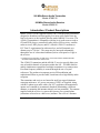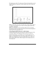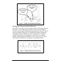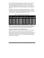
1
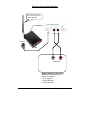
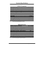
User’s Guide
Instructions for Installation and Operation
900 MHz Stereo Audio Transmitter
Model AT900-32
900 MHz Stereo Audio Receiver
Model AR900-32
Long Range Wireless Applications
(This page intentionally left blank)
900 MHz Stereo Audio Transmitter
Model AT900-32
900 MHz Stereo Audio Receiver
Model AR900-32
Introduction / Product Descriptions
Model AT900-32 from Applied Wireless, Inc. is a high quality transmitter
designed to broadcast excellent quality low noise stereo audio from any
line level source, to the Applied Wireless model AR900-32 receiver. The
AT900-32 transmitter is compatible with line level audio sources such as
CD and DVD players, commercial radio (AM or FM) receivers, satellite
radio receivers, MP3 players, and PCs. Model AT900-32 conforms to
FCC Part 15 requirements for unlicensed use, and will transmit over
distances up to 750 feet.* The range may be increased substantially
through the use of a directional antenna (such as a flat panel or Yagi) at
the receiver.
* Unobstructed, straight line-of-sight range, when used with the standard antennas
included with the transmitter and receiver.
The AT900-32 transmitter and the AR900-32 receiver provide thirty-two
user-selectable channels of operation within the 902 – 928 MHz band to
enable simultaneous operation of multiple transmitters in a common area.
Excellent frequency stability is assured through the use of crystal
references. The products incorporate precise FM modulation and
sophisticated filters to provide stable, interference-free high fidelity audio
reception.
The transmitter and receiver are housed in small yet rugged aluminum
extrusion enclosures. AC power converters (9VDC) are supplied, along
with RCA phono-type audio cables. By FCC regulation, the transmitter’s
quarter-wave antenna is permanently attached (substituting a different
antenna, or mounting the antenna remotely are not permitted). The antenna
supplied with the receiver is a removable quarter-wave ground plane
(sometimes referred to as a half-wave) antenna. The receiver’s antenna
User’s Guide – 900MHz Stereo Audio Transmitter & Receiver
1
attaches with a BNC connector, enabling the use of an alternative antenna,
(such as a directional flat panel or Yagi) to increase operating range
(please contact Applied Wireless for a selection of available antennas).
The AT900-32 transmitter and the AR900-32 receiver are well-suited for
many diverse applications, including distribution of audio entertainment
content throughout a building, home theater installations, commercial and
industrial surveillance, monitoring, security, etc.
Installation Instructions
Before Beginning the Installation
Plan your installation carefully. The physical location and orientation of
the transmitter and receiver antennas (relative to each other and their
surroundings) will have a significant influence on reception quality at the
receiver. The following guidelines will generally yield the best results:
•
•
•
•
Both the transmitter antenna and the receiver antenna should be
positioned vertically (pointing either up or down).
Antennas should be positioned high enough to enable people to move
about below them without creating obstructions between the antennas.
Although the RF signal from the transmitter will pass through most
non-metallic building materials (wood, stucco, brick, etc.), its strength
is reduced with every wall through which it must pass. Therefore,
maximum stated reception range is based on unobstructed line of sight
conditions.
The transmitter and receiver are both rated for indoor use only. If
either unit must be located outdoors, it must be protected from the
elements (using, for example, a non-metallic NEMA4 enclosure).
Connecting Audio to the AT900-32 Transmitter
Connect a line level stereo audio source (outputs from a CD player, for
example) to the corresponding LEFT and RIGHT line-level input jacks on
the transmitter’s rear panel (refer to Figure 1). A shielded dual cable is
supplied with the transmitter for making these connections. Some audio
devices, such as MP3 players, portable CD players, and PC sound cards
have a single miniature (3.5mm) stereo phone jack (as opposed to separate
2
Applied Wireless, Inc.
RCA phono-type jacks). To connect any of these to the transmitter, use the
supplied adaptor in conjunction with the standard dual cable to make the
connection.
Figure 1 – AT900-32 Transmitter (Rear Panel)
Note 1: If the audio source device provides only a single (mono) output, a
“Y” adaptor (not supplied) may be used to feed the signal to both of the
transmitter’s input jacks.
Note 2: If a microphone is to be used as the audio source, an external
microphone preamp (not supplied) must be used to raise the microphone’s
output signal to the required line level.
Connecting the AR900-32 Receiver’s Audio Outputs
Using the shielded dual audio cable provided, connect the receiver’s line
level audio outputs to the appropriate inputs on the device that is to
amplify and reproduce (or record) the received audio signals (refer to
Figure 2). If the destination device has only a single (mono) input, a “Y”
adaptor (not supplied) may be used to combine the receiver’s LEFT and
RIGHT outputs, and feed the combined signal to the destination device’s
mono input jack.
User’s Guide – 900MHz Stereo Audio Transmitter & Receiver
3
Figure 2 – AR900-32 Receiver (Rear Panel)
Connecting Power to the Transmitter and Receiver
The AT900-32 and the AR900-32 each require an external power source
of between 7.5 and 18 volts DC. A plug-in 120VAC-to-9VDC power
converter is supplied with each unit. Insert the power converter’s 2.1mm
plug into the DC INPUT jack on the unit’s rear panel (refer to Figures 1 and
2). Plug each converter into a live 120VAC outlet. The transmitter’s red
POWER indicator LED (on the front panel) should illuminate. On the
receiver, power on is indicated by the illumination of the 2 digit CHANNEL
display.
User Settings and Adjustments
Selecting the Channel of Operation (Transmitter)
Referring to Figure 3 and Table 1, select the channel on which the
transmitter will operate. Available channels are numbered 01 through 32.
To select a channel, use a small flat-blade screwdriver to rotate the
selector on the left to the “tens digit” of the desired channel, then rotate
the selector on the right to the “ones digit” of the desired channel. As an
example, to select channel 26 rotate the selector on the left to “2,” and
rotate the selector on the right to “6.” Be sure to line up the selector’s
triangle-shaped pointer (NOT the screwdriver slot) to the desired number.
Please note that setting the channel to “00” is the same as channel “01.”
Similarly, setting the channel to any number from “33” to “99” is the same
as channel “32.”
If several AT900-32 transmitters are to be used simultaneously in a
common area (so as to broadcast multiple audio programs), each
transmitter must be set to its own unique channel.
4
Applied Wireless, Inc.
Set this selector
to the “ones” digit
of the desired
channel
Set this selector
to the “tens” digit
of the desired
channel
Figure 3 – AT900-32 Transmitter (Front Panel)
Selecting the Channel of Operation (Receiver)
The AT900-32 provides 32 user-selectable channels. Referring to Figure 4
and Table 1, use the DOWN and UP buttons on the unit’s front panel to
select the desired channel. Momentarily pressing either button will raise or
lower the displayed channel by one; holding either button continuously
will rapidly cycle the channels up or down as appropriate. If multiple
AT900-32 transmitters are operating in a common area to broadcast
multiple audio programs, the AR900-32 receiver can receive any of the
desired programs simply by selecting the corresponding channel.
Figure 4 – AR900-32 Receiver (Front Panel)
User’s Guide – 900MHz Stereo Audio Transmitter & Receiver
5
If you encounter sporadic noises, dropouts, fading, etc., it may be due to
interference from another 900MHz device (such as an older cordless
phone or baby monitor) operating nearby. To alleviate the problem, try
selecting a different channel for the transmitter and receiver – ideally one
that is at least 9MHz above or below the originally selected channel (see
Table 1).
Please note: Wireless devices that operate outside of the 902 – 928MHz
frequency band, such as modern cordless phones and computer networks
operating at 2.4 or 5.8GHz, will not generally interfere with, or be affected
by, the AT900-32 transmitter and/or the AR900-32 receiver.
Table 1 – Channel / Frequency Allocations
Channel
Number
Frequency
(MHz)
Channel
Number
Frequency
(MHz)
Channel
Number
Frequency
(MHz)
Channel
Number
Frequency
(MHz)
01
02
03
04
05
06
07
08
905.0
906.2
923.6
924.4
925.6
910.6
911.8
913.4
09
10
11
12
13
14
15
16
914.2
915.4
917.0
917.8
919.0
920.6
921.4
922.6
17
18
19
20
21
22
23
24
905.6
906.6
907.6
908.8
910.0
911.2
912.4
913.8
25
26
27
28
29
30
31
32
915.0
916.2
917.4
918.4
919.6
921.0
921.8
923.0
NOTE 1: Setting the transmitter to channel “00” is the same as channel 1. Similarly, setting the
transmitter’s channel to any number from “33” to “99” (inclusive) is the same as channel 32.
NOTE 2: If the AT900-32 and AR900-32 will be used along with an Applied Wireless video transmitter
and receiver (models VT900-3 and VR900-3), the channel for the audio units must be at least 9MHz
above or below the channel of the video units, to prevent interference between the RF signals. For
example, if the video units are set to channel 1 (907MHz), set the audio units to channel 32.
Setting the Transmitter’s Audio Modulation Level
With an active audio source connected to the transmitter’s AUDIO INPUTS,
adjust the AUDIO LEVEL control on the front panel such that the green
MODULATION LEVEL OK indicator is illuminated whenever audio is present,
and the red PEAK indicator flashes only on the loudest audio transients. To
prevent distorted audio at the receiver, the red PEAK indicator should not
be illuminated continuously.
6
Applied Wireless, Inc.
IMPORTANT!
Properly setting the transmitter’s modulation level is
CRITICAL to satisfactory operation of the transmitter,
and receiver. If the level is set too low, the receiver will
likely be plagued with objectionable background noise
(hiss). If the level is set too high, distorted audio
and/or interference on adjacent channels is likely to
result.
Note: The audio source device may have a volume control that adjusts the
level of the audio signal(s) being fed to the transmitter’s inputs. If your
source device (e.g. MP3 player, portable CD player, or PC sound card) is
so equipped, initially set that device’s volume control to its approximate
midpoint. Then, adjust the transmitter’s AUDIO LEVEL control as described
above. Use the following guidelines to “fine tune” the settings:
•
If the audio output at the receiver suffers from excessive background
noise, the source device’s volume level is probably set too low.
Increase the source device’s volume control a bit, and readjust the
transmitter’s AUDIO LEVEL control accordingly.
•
If the audio output at the receiver is distorted, and/or if the
transmitted audio program can be heard on (or interferes with) either
or both of the channels adjacent to the selected channel of operation,
the source device’s volume level is probably set too high. Reduce the
source device’s volume control a bit, and readjust the transmitter’s
AUDIO LEVEL control accordingly.
User’s Guide – 900MHz Stereo Audio Transmitter & Receiver
7
Adjusting Headphone Volume (Receiver)
If desired, stereo headphones or earbuds equipped with a standard 3.5mm
mini-phone plug may be used with the AR900-32 receiver. Insert the plug
into the HEADPHONE jack on the rear panel. The output level at this jack
may be adjusted using the VOLUME control on the front panel.
Note: The receiver’s VOLUME control only affects the volume at the
headphone jack. It does not affect the volume at the receiver’s line level
audio output phono jacks.
EQualization (Receiver)
When headphones or earbuds are used with the receiver, the EQ button on
the receiver’s front panel may be used to select one of four preset audio
equalization (tone) profiles, enabling you to select the audio response
characteristics that you prefer. The chosen equalization profile only affects
the audio from the headphone jack on the rear panel. The audio signals at
the line level audio output phono jacks remain “flat” regardless of the
equalization profile chosen for the headphones.
Momentarily pressing the EQ button will cause the 2-digit CHANNEL
indicator to display the current equalization profile. The four equalization
profiles are as follows:
•
•
•
•
E1: No Equalization (flat response)
E2: Bass Boost
E3: Treble Boost
E4: Bass Boost + Treble Boost
Pressing the EQ button again (while the display is indicating the
equalization profile) will advance to the next profile. The 2-digit CHANNEL
indicator will automatically revert to displaying the receiver’s current
channel when the EQ button has not been pressed for two to three seconds.
8
Applied Wireless, Inc.
Transmitter Connection Diagram
For maximum range, the
transmitter’s antenna must be
oriented vertically.
Rear panel of transmitter
AC Adaptor
Dual RCA phono jack
to 3.5mm mini phone
plug adaptor
3.5mm Stereo
Output Jack
Right
Left
Audio Outputs
Audio Source Device
with RCA phono jack outputs,
for example:
• CD player
• DVD player
• Tuner
• Satellite radio receiver
Audio Source Device
with 3.5mm mini phone jack
stereo output, for example:
• MP3 player
• Portable CD player
• PC Sound Card
User’s Guide – 900MHz Stereo Audio Transmitter & Receiver
9
Receiver Connection Diagram
For maximum range, the
receiver’s antenna must be
oriented vertically.
Rear panel of receiver
AC Adaptor
Left
Right
Audio Inputs
Audio Playback (or Recording)
Device with RCA phono jack
inputs, for example:
• P.A. Amplifier
• Stereo Receiver
• Audio Recorder
10
Applied Wireless, Inc.
Internal Settings
The AT900-32 transmitter and the AR900-32 receiver each have internal
jumpers and/or switches (on their respective printed circuit boards) that
are preset at the factory to provide the proper configuration for most
applications. The following sections describe these settings, and provide
guidelines for when it may be necessary or desirable to modify them.
CAUTION!
The AT900-32 transmitter and the AR900-32 receiver both contain
sensitive electronic components on their respective circuit
boards. These devices can be permanently damaged by static
discharge if adequate anti-static procedures are not observed.
Such damage is not covered by the Applied Wireless, Inc.
Limited Warranty. Before attempting to modify any of the internal
settings, discharge any static that may have accumulated on
your body by touching a metal object or surface that is earth
grounded, such as a cold water pipe. In addition, your work area
should be as static-free as possible (for example, do not work in
an area in which the floor is covered by nylon carpeting).
In order to modify any internal settings, the unit’s circuit board must
be removed from the enclosure, as follows:
1. Disconnect the power and audio cables from the unit.
2. For the receiver, remove the antenna. For the transmitter, the
antenna is permanently attached. Do not attempt to remove it.
3. For the receiver, remove the VOLUME knob.
4. For the transmitter, remove the two Phillips screws securing the
front panel.
5. For the receiver, remove the two Phillips screws securing the rear
panel.
6. The two long edges of the circuit board are retained in lengthwise
grooves along the inside walls of the enclosure. Gently slide the
circuit board out of the enclosure. As you remove the circuit board,
hold it by its edges only.
7. Once the internal setting(s) have been modified as necessary,
reassemble the unit by reversing the steps above.
User’s Guide – 900MHz Stereo Audio Transmitter & Receiver
11
Local/Distance (DX) Jumper (Receiver)
The AR900-32 receiver has an internal jumper that determines the
receiver’s RF sensitivity. The factory default position for this jumper is the
Distance (DX) setting, configuring the receiver for maximum sensitivity.
This is the appropriate setting for most applications (to allow for
maximum reception range). However, if multiple AT900-32 transmitters
are to be used in a common area (so as to broadcast multiple audio
programs), and any are set to operate on numerically adjacent channels,
there is a possibility of interference from one channel to the adjacent
channel. Switching the jumper to the LOCAL setting on any receiver(s) that
exhibit such interference may reduce or eliminate this interference. To do
this, perform the following steps:
1. Locate the LOCAL/DX jumper on the circuit board. In its factory
default position, the jumper connects the middle pin of the 3-pin
group to the DX pin, leaving the LOCAL pin open.
2. Remove the jumper from its default position, and reinsert it such
that it connects the middle pin to the LOCAL pin (leaving the DX pin
open).
12
Applied Wireless, Inc.
Noise Reduction (Transmitter and Receiver)
The transmitter and receiver are each equipped with active noise reduction
circuits that minimize objectionable background noise (or “hiss”) which
might otherwise be noticeable during periods of silence, such as the pause
between tracks on a CD. These circuits are normally enabled (factory
default). However, if the particular audio source material has very few (if
any) silent pauses, the noise reduction circuits may be turned off, to give
the sound a somewhat “brighter” or “livelier” character.
To de-activate the noise reduction circuits, locate the NR switches on the
transmitter and receiver printed circuit boards. Slide the actuator of each
switch to its NR OFF position.
Note 1: Be sure to readjust the transmitter’s audio modulation level (as
described on pages 6and 7) anytime the noise reduction circuits are either
activated or turned off.
Note 2: The noise reduction switches in the transmitter and the receiver
must be set to match each other (either on or off), in order to maintain
balanced audio frequency response.
User’s Guide – 900MHz Stereo Audio Transmitter & Receiver
13
Technical Specifications
AT900-32 Transmitter
Operating Frequency (32 Channels)
Operating Voltage Range
Operating Current
Audio Signal-to-Noise Ratio*
Audio Frequency Response (+/-3dB)*
Audio Channel (L/R) Separation (@ 1KHz)*
Audio Distortion (@ 1kHzm +/-25KHz deviation)*
Stereo Pilot Level
RF Output Power
Frequency Stability (over operating temp.range)
FM Deviation
Harmonic Suppression
Antenna Output Impedance
Operating Temperature Range
Storage Temperature Range
902 – 928 MHz
7.5 to 18VDC
120 mA
78 dB
50 - 15,000 Hz
30 dB
0.3%
-20 dBc
1 mW (0 dBm)
+/-30 ppm
+/-75 KHz
-45 dBc
50 Ohms
-20°C to +70°C
-50°C to +150°C
*Audio performance specifications are “end-to-end” characteristics,
when used with Model AR900-32 receiver.
AR900-32 Receiver
Operating Frequency (32 Channels)
Operating Voltage Range
Operating Current
Audio Frequency Response (+/-3dB, flat EQ)*
Audio Channel (L/R) Separation (@ 1KHz)*
Audio Signal-to-Noise Ratio*
Audio Distortion (@ 1kHzm +/-25KHz deviation)*
RF Input Sensitivity (30 dB SNR)
IF Bandwidth
Antenna Input Impedance
Frequency Stability (over operating temp. range)
Operating Temperature Range
Storage Temperature Range
902 – 928 MHz
7.5 to 18VDC
140 mA
50 - 15,000 Hz
30 dB
50 dB
0.3%
-106 dBm
180 KHz
50 Ohms
+/-30 ppm
-20°C to +70°C
-50°C to +150°C
*Audio performance specifications are “end-to-end” characteristics,
when used with Model AT900-32 transmitter.
14
Applied Wireless, Inc.
The following sections pertain exclusively to the Audio Transmitter,
Model AT900-32:
This product incorporates transmitter module FCC ID: QY4265
This device complies with Part 15 of the FCC Rules. Operation is subject
to the following two conditions:
(1) This device may not cause harmful interference and
(2) This device must accept any interference received, including
interference that may cause undesired operation.
INSTRUCTION TO THE USER (required by the FCC)
This equipment has been tested and found to comply with the limits for a
class B digital device, pursuant to part 15 of the FCC Rules. These limits
are designed to provide reasonable protection against harmful interference
in a residential installation. This equipment generates, uses and can radiate
radio frequency energy and if not installed and used in accordance with
the instructions, may cause harmful interference to radio communications.
However, there is no guarantee that interference will not occur in a
particular installation. If this equipment does cause harmful interference to
radio or television reception, which can be determined by turning the
equipment off and on, the user is encouraged to try to correct the
interference by one or more of the following measures:
•
Reorient or relocate the receiving antenna.
•
Increase the separation between the equipment and receiver.
•
Connect the equipment into an outlet on a circuit different from
that to which the receiver is connected.
•
Consult the dealer or an experienced radio/TV technician for help.
This equipment has been certified to comply with the limits for a class B
computing device, pursuant to FCC Rules. In order to maintain
compliance with FCC regulations, shielded cables must be used with this
equipment. Operation with non-approved equipment or unshielded cables
is likely to result in interference to radio and TV reception. The user is
cautioned that changes and modifications made to the equipment without
the approval of manufacturer could void the user’s authority to operate
this equipment.
User’s Guide – 900MHz Stereo Audio Transmitter & Receiver
15
ONE YEAR LIMITED WARRANTY (USA)
Products
manufactured
by
APPLIED
This warranty is extended to the original
WIRELESS, INC. (AW) and sold to purchasers
purchaser of the product(s) only, and is not
in the USA are warranted by AW according to
transferable to any subsequent owner or
the following terms and conditions. You should
owners of the product(s). AW reserves the right
read this Warranty thoroughly.
to make changes or improvements in its
products without incurring any obligation to
• WHAT IS COVERED, AND DURATION OF
similarly alter products previously purchased.
COVERAGE:
• EXCLUSION OF INCIDENTAL OR
AW warrants the product to be free from
CONSEQUENTIAL DAMAGES:
defects in materials and workmanship for one
AW expressly disclaims liability for incidental
(1) year from the date of purchase by the
and consequential damages caused (or
original end user purchaser.
allegedly caused) by the product. The term
• WHAT IS NOT COVERED:
“incidental or consequential damages” refers
This warranty does not apply to the following:
(but is not limited) to:
1. Damage caused by accident, physical or
1. Expenses of transporting the product to
electrical misuse or abuse, improper
AW to obtain service.
installation, failure to follow instructions
2. Loss of use of the product.
contained in the User’s Guide, any use
3. Loss of the original purchaser’s time.
contrary to the product’s intended
• LIMITATION OF IMPLIED WARRANTIES:
function, unauthorized service or alteration
This warranty limits AW’s liability to the repair
(i.e. service or alteration by anyone other
or replacement of the product. AW makes no
than AW).
express warranty of merchantability or fitness
2. Damage occurring during shipment.
for use. Any implied warranties, including
3. Damage caused by acts of God, including
fitness for use and merchantability, are limited
without limitation: earthquake, fire, flood,
in duration to the period of the one (1) year
storms, or other acts of nature.
express limited warranty set forth herein. The
4. Damage or malfunction caused by the
remedies provided under this warranty are
intrusion
of
moisture
or
other
exclusive and in lieu of all others. AW neither
contamination within the product.
assumes nor authorizes any person or
5. Batteries supplied by AW in or for the
organization to make any warranties or assume
product.
any liability in connection with the sale,
6. Cosmetic deterioration of chassis, cases,
installation, or use of this product.
or pushbuttons resulting from wear and
tear typical of normal use.
Any cost or expense related to troubleshooting to determine whether a
malfunction is due to a defect in the
product itself, in the installation, or any
combination thereof.
8. Any cost or expense related to repairing or
correcting the installation of an AW
product.
9. Any cost or expense related to the
removal or reinstallation of the product.
10. Any product whose serial number or date
code is altered, defaced, obliterated,
destroyed, or removed.
7.
16
Some states do not allow limitations on how
long an implied warranty lasts, and some states
do not allow the exclusion or limitation of
liability for incidental or consequential damages
so the limitations or exclusions stated herein
may not apply to you. This warranty gives you
specific legal rights and you may have other
rights which vary from state to state.
(continued on next page)
Applied Wireless, Inc.
ONE YEAR LIMITED WARRANTY (USA), cont.
•
HOW TO OBTAIN WARRANTY SERVICE:
If a product covered by this warranty and sold in the USA by AW proves to be defective during the
warranty period AW will, at its sole option, repair it or replace it with a comparable new or
reconditioned product without charge for parts and labor, when said product is returned in compliance
with the following requirements:
1. You must first contact AW at the following address/phone for assistance:
APPLIED WIRELESS, INC.
1250 Avenida Acaso, Suite F
Camarillo, CA 93012
Phone: (805) 383-9600
If you are instructed to return your product directly to the factory, a Return Merchandise
Authorization number (RMA) will be issued to you.
2.
You must package the product carefully and ship it insured and prepaid. The RMA number must
be clearly indicated on the outside of the shipping container. Any product returned without an
RMA number will be refused delivery.
3.
(a)
(b)
(c)
In order for AW to perform service under warranty, you must include the following:
Your name, return shipping address (not a PO Box), and daytime telephone number.
Proof of purchase showing the date of purchase.
A detailed description of the defect or problem.
Upon completion of service, AW will ship the product to the specified return shipping address. The
method of shipping shall be at AW’s sole discretion. The cost of return shipping (within USA) shall be
borne by AW.
User’s Guide – 900MHz Stereo Audio Transmitter & Receiver
17
Applied Wireless products are designed and manufactured with
pride in the United States of America
© Copyright 2007 by Applied Wireless, Inc. All rights reserved.
Specifications subject to change without notice.
APPLIED WIRELESS, INC.
1250 Avenida Acaso, Camarillo, CA 93012
Phone: 805-383-9600 Fax: 805-383-9001
Email: [email protected]
www.appliedwireless.com
Pub. # UG-ATR90032
Rev. date 03/07