1
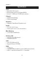
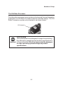
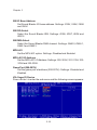
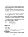
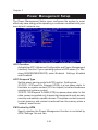
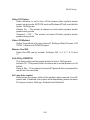
VIA
User’s Manual
VIA EPIA
Mini-ITX Mainboard
Version 1.0
March 21, 2002
P/N 99-51-010061
i
Copyright
Copyright by VIA Technologies Inc. (“VIA”). No part of this manual may
be reproduced or transmitted in any form without express written
authorization from VIA.
Trademarks
All trademarks are the property of their respective holders.
Data protection
All data should be backed-up prior to the installation of any drive unit or
storage peripheral. VIA will not be responsible for any loss of data resulting
from the use, disuse or misuse of this or any other VIA product.
No Warranty
VIA has made every effort to ensure the accuracy of the content of this
manual. However, it is possible that it may contain technical
inaccuracies or typographical or other errors. VIA will assume no liability
for any inaccuracy found in this publication, nor for damages, direct,
indirect, incidental, consequential or otherwise, that may result from
such an inaccuracy, including without limitation loss of data or profits.
VIA provides this manual “as is”, and does not issue a warranty of any
kind, express or implied, including without limitation implied warranties
of merchantability or fitness for a particular purpose.
The information provided in this manual is subject to change without
notice. VIA reserves the right to alter product designs, layouts or drivers
without notification.
ii
FCC-B Radio Frequency Interference Statement
This equipment has been tested and found to comply with the limits for a
class B digital device, pursuant to part 15 of the FCC rules. These limits
are designed to provide reasonable protection against harmful interference when the equipment is operated in a commercial environment. This
equipment generates, uses and can radiate radio frequency energy and,
if not installed and used in accordance with the instruction manual, may
cause harmful interference to radio communications. Operation of this
equipment in a residential area is likely to cause harmful interference, in
which case the user will be required to correct the interference at his own
expense.
Notice 1
The changes or modifications not expressly approved by the party responsible for compliance could void the user’s authority to operate the
equipment.
Notice 2
Shielded interface cables and A.C. power cord, if any, must be used in
order to comply with the emission limits.
VOIR LA NOTICE D’INSTALLATION AVANT DE RACCORDER AU
RESEAU.
VIA EPIA Mini-ITX Mainboard
Tested to comply
with FCC Standard
For Home or Office Use
iii
Safety Instructions
NOTE
1. Always read the safety instructions carefully.
2. Keep this User’s Manual for future reference.
3. Keep this equipment away from humidity.
4. Lay this equipment on a reliable flat surface before setting it up.
5. The openings on the enclosure are for air convection hence protects
the equipment from overheating. DO NOT COVER THE OPENINGS.
6. Make sure the voltage of the power source and adjust properly 110/
220V before connecting the equipment to the power inlet.
7. Place the power cord in such a way that people cannot step on it.
Do not place anything over the power cord.
8. Always unplug the power cord before inserting any add-on card or
module.
9. All cautions and warnings on the equipment should be noted.
10. Never pour any liquid into the opening. Liquid can cause damage or
electrical shock.
11. If any of the following situations arises, get the equipment checked
by a service personnel:
• The power cord or plug is damaged
• Liquid has penetrated into the equipment
• The equipment has been exposed to moisture
• The equipment has not work well or you can not get it work
according to User’s Manual.
• The equipment has dropped and damaged
• If the equipment has obvious sign of breakage
12. DO NOT LEAVE THIS EQUIPMENT IN AN ENVIRONMENT UNCONDITIONED, STORAGE TEMPERATURE ABOVE 600 C (1400F), IT
MAY DAMAGE THE EQUIPMENT.
CAUTION: Explosion or serious damage may occur if the
battery is incorrectly replaced. Replace only with the same
or equivalent type recommended by the manufacturer.
iv
Box Contents
This VIA EPIA Mini-ITX Mainboard package should contain the following
items:
•
1 x VIA EPIA Mini-ITX Mainboard
•
1 x User’s manual
•
1 x ATA-33/66/100 Hard drive ribbon cables
•
1 x Driver Utilities CD
•
1 x I/O Bracket
v
Contents
1. Specifications .......................................... 1-1
Specifications ........................................................ 1-2
Layout .................................................................... 1-4
Connectors Guide .................................................. 1-5
2. Installation ................................................ 2-1
CPU ....................................................................... 2-2
Memory Installation ................................................. 2-4
Power Supply ......................................................... 2-6
Back Panel ............................................................ 2-7
Connectors ............................................................ 2-9
Jumpers ............................................................... 2-14
Slots .................................................................... 2-18
PCI Interrupt Request Routing ............................... 2-19
3. BIOS Setup ............................................... 3-1
Entering Setup ....................................................... 3-2
Control Keys .......................................................... 3-2
Getting Help ........................................................... 3-3
The Main Menu ....................................................... 3-4
Standard CMOS Features ...................................... 3-6
Advanced BIOS Features ....................................... 3-8
Advanced Chipset Features .................................. 3-11
Integrated Peripherals .......................................... 3-15
Power Management Setup ................................... 3-20
PNP/PCI Configurations ....................................... 3-26
PC Health Status .................................................. 3-29
Load Fail-Safe Defaults ....................................... 3-30
Load Optimized Defaults ...................................... 3-31
Set Supervisor/User Password ............................ 3-32
Save & Exit Setup ................................................ 3-34
Exit Without Saving .............................................. 3-35
vi
4. Software Setup ........................................ 4-1
VIA Apollo PLE133 Chipset Drivers ....................... 4-2
VIA PLE133 Integrated VGA Driver ...................... 4-12
VIA Audio Driver ................................................... 4-14
VIA Network Driver ............................................... 4-15
VIA Fast InfraRed Device Driver ........................... 4-30
vii
Specifications
1. Specifications
The ultra-compact and highly intergrated VIA EPIA Mini-ITX Mainboard
is the smallest form factor mainboard specification available today,
developed by VIA Technologies, Inc as part of the company’s open
industry-wide Total Connectivity initiative. The VIA EPIA Mini-ITX
mainboard enables the creation of an exciting new generation of small,
ergonomic, innovative and affordable embedded systems. Through high
levels of integration, mini-ITX only occupies 66% of the size of the FlexATX
mainboard form factor. The mainboard comes with an embedded VIA
Processor, boasting ultra low power consumption and cool, quiet
operation.
This chapter includes the following sections:
Mainboard Specifications
Mainboard Layout
Components Guide
1-1
1-2
1-4
1-5
Chapter 1
Specifications
CPU
• Embedded VIA Processor
• Enhanced Ball Grid Array Package (EBGA)
• Internal L1 128KB and L2 64KB cache memory
Chipset
• VIA 8601A North Bridge
• VT8231 South Bridge
Graphics
• Integrated Trident Blade 3D graphics core
Audio
• VT1612A AC’97 Codec
• 3 Audio jacks: Line-in, Line-out and Mic-in
Main Memory
• 2 x PC100/133 DIMM slots.
PCI Bus IDE
• Supports up to 4 IDE devices
• Ultra DMA 33/66/100
LAN
• VIA VT6103 Ethernet PHY
• Supports Ethernet 10/100Mb
USB
• 2 USB ports
• 1 onboard USB pin header for up to 2 additional connections
• USB v1.1 and Intel Universal HCI v1.1 compatible
1-2
Specifications
TV-Out
• VIA VT1621 TV-Out Controller
• Supports 640 x 480, 800 x 600 NTSC/PAL TV
• S-Video or RCA Video output
I/O Ports
• 1 PS2 Mouse connenctor
• 1 PS2 Keyboard connector
• 1 15-pin External Monitor connector
• 1 16C550 compliant serial port
• 1 EPP/ECP complaint parallel port
• 1 FIR port jumper pin
• 1 CIR jumper pin
Power
• Supports ATX type power supply
1-3
Chapter 1
Layout
VIA EPIA Mini-ITX Mainboard
(Note: Onboard DOC is optional)
1-4
Specifications
Connectors Guide
Component
Fan 1, Fan 2
DIMM1, DIMM2
ATX Power Connector
PS/2 Mouse
PS/2 Keyboard
LPT Connector
RJ-45 Port
COM Port
Line Out
Line In
Mic In
USB 0, USB 1
RCA Video or S/P DIF
S-Video
CRT connector
IDE 1, IDE 2
J3
J7
J5
J6
J8
J9
J12
J10
J13
J2
J1
J4
J11
PCI Slot
Function
Fan power connectors
DIMM slot
Connecting ATX power supply
Mouse connector
Keyboard connector
Parallel port connector
Connecting to a LAN
COM port connector
Connecting Headphones/Speakers
Connecting an audio device
Connecting a Micorphone
Connecting to USB devices
Connecting to RCA Video or SPDIF
Connecting to S-Video
Connect to CRT monitor
Connecting IDE devices
Front panel connectors
CD-ROM Line in connector
FIR module connector
CIR module connector
Wake on Modem
USB Port 2 &3 Connector
Video In and PCI Riser connector
Clear CMOS jumper
Host Frequency Select
Auto Reboot Function Setting
CPU Strapping Function Setting
Disk On Chip (DOC) BIOS
RCA Video / S/P DIF
Connecting to expansion cards
1-5
Reference
See p. 2-2
See p. 2-4
See p. 2-6
See p. 2-7
See p. 2-7
See p. 2-7
See p. 2-7
See p. 2-8
See p. 2-8
See p. 2-8
See p. 2-8
See p. 2-8
See p. 2-8
See p. 2-8
See p. 2-8
See p. 2-9
See p. 2-10
See p. 2-10
See p. 2-11
See p. 2-11
See p. 2-12
See p. 2-12
See p. 2-13
See p. 2-14
See p. 2-15
See p. 2-16
See p. 2-16
See p. 2-17
See p. 2-17
See p. 2-18
Hardware Setup
2. Installation
This chapter provides you with information about hardware setup
procedures. While installating, be careful in holding the components
and follow the installation procedures. Some components can be damaged
if installed incorrectly. If possible, use a grounded wrist strap before
handling computer components. The components can be damaged by
static electricity.
This chapter contains the following topics:
Central Processing Unit (CPU)
Memory Installation
Power Supply
Back Panel
Connectors
Jumpers
Slots
PCI Interrupt Request Routing
2-1
2-2
2-4
2-6
2-7
2-9
2-14
2-18
2-19
Chapter 2
CPU
The VIA EPIA Mini-ITX Mainboard includes an embedded VIA Eden
Processor or VIA C3TM E-Series Processor. Two fan connectors (Fan 1 &
Fan 2) are provided on the mainboard, alllowing for the connection of a
CPU fan and an additional system case fan.
The VIA C3TM E-Series Processor
With low power consumption and advanced thermal dissipation properties,
the embedded VIA C3TM E-Series requires only a small fan to guarantee
performance and reliability. Ensure that the CPU Fan Connector is
correctly installed, as displayed below.
CPU Fan Cable
CPU Fan Connector
2-2
CPU Fan / Heatsink
Hardware Setup
The VIA Eden Processor
Providing ultra-low power consumption and advanced thermal dissipation
properties, the VIA Eden Processor features a fanless design. The VIA
Eden Processor requires only a heatsink, as shown below.
CPU Heatsink
WARNING!
Overclocking
This motherboard is not designed to support overclocking.
Any attempt to operate beyond product specifications is
not recommended. We do not guarantee the damages
or risks caused by operation beyond product
specifications.
2-3
Chapter 2
Memory Installation
The VIA EPIA Mini-ITX Mainboard provides two 168-pin DIMM slots for
PC 100/133 SDRAM memory modules. To operate properly, at least one
module must be installed.
DIMM 1 & DIMM 2
SDRAM Module Installation Procedures
1.) Push the white retaining latches at either end of the DIMM slot
outwards.
2.) Align the SDRAM module with the corresponding notches on the
DIMM slot. The modules will only fit if placed in the correct position.
2.) With both hands, press the SDRAM module down into the DIMM slot
so that the white retaining latches rotate up and secure the module in
place (see picture below).
2-4
Hardware Setup
Available SDRAM Configurations
Refer to the table below for available SDRAM configurations on the VIA
EPIA Mini-ITX Mainboard.
Socket
Mem ory Module
DIMM 1
32MB, 64MB, 128MB, 32MB~512MB
256MB, 512MB
32MB, 64MB, 128MB, 32MB~512MB
256MB, 512MB
DIMM 2
Maximum System Mem ory Supported
2-5
Total Mem ory
1GB
Chapter 2
Power Supply
The VIA EPIA Mini-ITX Mainboard requires an ATX power supply to be
connected. Before inserting the power supply connector, always make
sure that all components are installed correctly to ensure that no damage
will be caused.
ATX 20-Pin Power Connector
To connect the ATX power supply, make sure the plugs of the power
supply are inserted in the proper orientation and the pins are correctly
aligned. Then, push down the power supply plug firmly into the connector.
2-6
Hardware Setup
Back Panel
The back panel of the VIA EPIA Mini-ITX Mainboard contains the following
connectors:
PS/2 Mouse
LPT Connector
PS/2 Keyboard
CRT Connector
RJ-45 Port
S-Video Port
USB Ports
RCA Video
or
S / P DIF Port
COM Port
Line Line Mic
Out In
In
(Audio Connectors)
PS/2 Mouse
You can connect a PS/2 mouse directly to this standard PS/2 mouse
connector.
PS/2 Keyboard
The mainboard provides a standard PS/2 keyboard connector for
connecting a PS/2 keyboard.
LPT Connector
The 25-pin female parallel port for connecting printers supports Enhanced
Parallel Port (EPP) and Extended Capabilities Parallel Port (ECP) modes.
RJ-45 Port
The mainboard provides a standard RJ-45 port for connection to a Local
Area Network (LAN).
2-7
Chapter 2
COM Port
The mainboard provides a 9-pin male serial port connector for connecting
a serial mouse or other serial devices.
Audio Connectors
Line Out is a connector for speakers or headphones. Line In is used for
an external CD player, tape player, or other audio devices. Mic In is a
connector for microphones.
USB Ports
The two Universal Serial Bus ports (USB 0 & USB 1) are for attaching
any USB 1.1 compliant devices such as a keyboard, mouse or digital
camera.
RCA Video or S/P DIF Port
This dual function port may be used either as a RCA Video port or as a
S/P DIF port. An onboard jumper (J11) allows you to select what the port
is used for. RCA Video provides a TV Out connection, while S/P DIF
provides a 5.1 channel digital audio connection.
S-Video Port
This port supporting 640 x 480 and 800 x 600 resolutions in NTSC and
PAL modes. If RCA Video function is selected, and both RCA Video/SVideo port are connected, only S-Video function will be enabled.
CRT Connector
Connect a CRT monitor to this connector for VGA display.
2-8
Hardware Setup
Connectors
The VIA EPIA Mini-ITX Mainboard provides the following connectors:
IDE Connectors
The two PCI IDE connectors (IDE 1 & IDE 2) support Ultra DMA 33/66/
100 modes. IDE 1 is the primary IDE connector and IDE 2 is the secondary
IDE connector. Both IDE 1 and IDE2 can connect a master and a slave
drive, allowing a maximum of four seperate devices, such as a HDD, CDROM or CD-RW, to be connected.
Also, a Disk on Module can be connected directly to one of the IDE
connectors.
These connectors utilize the provided IDE cable.
IDE 1 IDE 2
NB: If you install two HDDs on one IDE cable, you must set
the second drive to slave mode by setting its jumper on the
HDD. Please refer to the HDD documentation supplied by the
HDD vendor for correct jumper setiing instructions.
2-9
Chapter 2
Front Panel Connectors (J3)
The J3 front panel connectors allow you to connect the Power Switch,
Reset Switch, Power LED and HDD LED to the system case.
1
2
HDD LED
Power LED
Power Switch
Reset
11
12
CD-ROM Line In Connector (J7)
The J7 internal CD-ROM Line In Connector allows you to connect and
receive audio input from a device such as a CD-ROM.
1
L G G R
2-10
Hardware Setup
FIR Module Connector (J5)
The FIR Module Connector (J5) allows you to connect a Fast Infrared
standard module. This is not for standard FIR module, for reference design
please consult with VIA Technologies, Inc.
1
CIR Module Connector (J6)
The CIR Module Connector (J6) allows you to connect a Consumer Infrared
standard module. This is not for standard CIR module, for reference design
please consult with VIA Technologies, Inc.
1
2-11
Chapter 2
Wake On Modem Connector (J8)
This connector (J8) allows you to connect to a modem with the Wake On
Modem function. The connector will power up the system when a signal
is received through the modem.
1
USB Port 2 & 3 Connector (J9)
This connector (J9) allows you to connect an additional two Universal
Serial Bus (USB) ports, in case the two USB ports on the back panel are
not sufficient. To utilize the additional two USB connections you need to
connect a 2 port USB module to the J9 connector. This is not for standard
USB port module, for reference design please consult with VIA
Technologies, Inc.
1
2-12
Hardware Setup
Video In Connector and PCI Riser Card Connector (J12)
The Video In Connector (right part of J12, see diagram below) allows you
to connect an external video source. The PCI Riser Card Connector (left
part of J12, see diagram below) allows you to connect a PCI Riser Card
module. These connectors are not for standard Video In and PCI Riser
Card module, for reference design please consult with VIA Technologies,
Inc.
1
Video In Connector
PCI Riser Card Connector
2-13
Chapter 2
Jumpers
The VIA EPIA Mini-ITX Mainboard provides a series of jumpers to set the
computer’s functions. This section explains the functions of all the
mainboard settings.
Clear CMOS (J10)
The Clear CMOS jumper allows you to clear the CMOS memory of system
parameter settings. If you want to clear the system configuration, use
the JBAT1 (Clear CMOS Jumper ) to clear data. Follow the instructions
below to clear the data:
1
3
1
1
3
3
Normal
Clear CMOS
1-2: Normal
2-3: Clear CMOS
WARNING!
Do not clear the CMOS while the system is on;
it may cause damage to the mainboard.
2-14
Hardware Setup
Host Frequency Select (J13)
This jumper can be used to select the host frequency bus speed of the
mainboard. The three available options are 66MHz, 100MHz and 133MHz.
J13 Host Frequency
Select
WARNING! Overclocking
This motherboard is not designed to support overclocking.
Any attempt to operate beyond product specifications is
not recommended. We do not guarantee the damages
or risks caused by operation beyond product
specifications.
2-15
Chapter 2
Auto Reboot Function Setting (J2)
This jumper enables or disables the Auto Reboot Function Setting. When
enabled, the system will automatically reboot in the event of sudden
power outage.
1
1-2: Disable
2-3: Enable
CPU Strapping Function Setting (J1)
This jumper enables or disables the CPU Strapping Function Setting.
1
1-2: Disable
2-3: Enable
2-16
Hardware Setup
DOC BIOS Select (J4)
This jumper enables or disables the Disk on Chip (DOC) BIOS Select
Function. The DOC function is not a standard option on this mainboard
and is a manufacturing option only. Therefore the DOC function may not
be present on the mainboard you have purchased.
1
1-2: Disable
2-3: Enable
RCA Video or S/P DIF Select (J11)
This jumper selects either RCA Video or S/P DIF as the enabled function
on the dual purpose port.
3 1
4 2
1-2: RCA Video
3-4: S/P DIF
2-17
Chapter 2
Slots
PCI Slot
The PCI slot allows you to insert PCI expansion card. When adding or
removing expansion cards, make sure that you unplug the power supply
first. Meanwhile, read the documentation for the expansion card to make
any necessary hardware or software settings for the expansion card,
such as jumpers, switches or BIOS configuration.
For two PCI slot solution, a PCI Riser Card module can be used. For
reference design please consult with VIA Technologies, Inc.
2-18
Hardware Setup
PCI Interrupt Request Routing
The IRQ (Interrupt ReQuest) is the mechanism for devices to request
services from the microprocessor. The “PCI & LAN” IRQ pins are typically
connected to the PCI bus INT A# ~ INT D# pins as follows:
Order 1
Order 2
Order 3
Order 4
PCI Slot 1
INT B#
INT C#
INT D#
INT A#
LAN
INT B#
2-19
BIOS Setup
3. BIOS Setup
This chapter gives detailed explaination of the BIOS setup functions. It
consists of the following topics:
Entering Setup
Control Keys
Getting Help
The Main Menu
Standard CMOS Features
Advanced BIOS Features
Advanced Chipset Features
Integrated Peripherals
Power Management Setup
PNP/PCI Configurations
PC Health Status
Load Fail-Safe Defaults
Load Optimized Defaults
Set Supervisor/User Password
Save & Exit Setup
Exit Without Saving
3-1
3-2
3-2
3-3
3-4
3-6
3-8
3-11
3-15
3-20
3-26
3-29
3-30
3-31
3-32
3-34
3-35
Chapter 3
Entering Setup
Power on the computer and press DEL straight away to enter the BIOS
setup menu.
If you missed the BIOS setup entry point, you may restart the system
and try again.
Control Keys
<↑>
M o v e t o t h e p r e v io u s it e m
<↓>
M o v e t o t h e n e x t it e m
<← >
M o v e t o t h e it e m in t h e le f t h a n d c o lu m n
<→ >
M o v e t o t h e it e m in t h e r ig h t h a n d c o lu m n
< E n te r >
S e le c t t h e it e m
<E sc>
J u m p s t o t h e E x it m e n u o r r e t u r n s t o t h e m a in
m e n u fro m a s u b m e n u
< + /P U >
I n c r e a s e t h e n u m e r ic v a lu e o r m a k e c h a n g e s
< -/P D >
D e c r e a s e t h e n u m e r ic v a lu e o r m a k e c h a n g e s
<F1>
G e n e r a l h e lp , o n ly f o r S ta t u s P a g e S e tu p M e n u
a n d O p t io n P a g e S e t u p M e n u
<F5>
R e s t o r e th e p r e v io u s C M O S v a lu e f r o m C M O S ,
o n l y f o r O p t io n P a g e S e t u p M e n u
<F6>
L o a d t h e d e f a u lt C M O S v a lu e f r o m F a il- S a f e
d e f a u lt t a b le , o n l y f o r O p t io n P a g e S e t u p M e n u
<F7>
L o a d O p t im iz e d d e f a u lts
<F10>
S a v e a ll t h e C M O S c h a n g e s a n d e x it
3-2
BIOS Setup
Getting Help
After entering the BIOS setup menu, the Main Menu appears.
Main Menu
The main menu displays all BIOS setup categories. Use the control
keys (LK) to select any item/sub-menu. A description of the selected/
highlighted category is displayed at the bottom of the screen.
Sub-Menu
If you find a right pointer symbol (as shown
in the window on the right) on the left of a
field, this means a sub-menu is available. The
sub-menu contains additional options. You
can use control keys (LK) to highlight the
field and press <Enter> to enter the submenu. To return from the sub-menu press
<Esc >.
IDE Primary Master
IDE Primary Slave
IDE Secondary Master
IDE Secondary Slave
General Help <F1>
The BIOS setup program provides a General Help screen. You can call
up this screen from any menu/sub-menu by pressing <F1>. The help
screen displays the keys for use and navigate the BIOS setup. Press
<Esc> to exit the help screen.
3-3
Chapter 3
The Main Menu
The Main Menu contains eleven setup functions and two exit choices.
Use arrow keys to select the items and press <Enter> to accept or enter
the sub-menu.
Standard CMOS Features
Use this menu to set basic system configurations.
Advanced BIOS Features
Use this menu to set the advanced features available on your system.
Advanced Chipset Features
Use this menu to set chipset specific features and optimize system
performance.
Integrated Peripherals
Use this menu to set onboard peripherals features.
Power Management Setup
Use this menu to set onboard power management functions.
PnP/PCI Configurations
Use this menu to set the PnP and PCI configurations.
3-4
BIOS Setup
PC Health Status
This menu shows the PC health status.
Load Fail-Safe Defaults
Use this menu to load the BIOS default settings for minimal and stable
system operations.
Load Optimized Defaults
Use this menu to load BIOS default settings for optimal and high
performance system operations.
Set Supervisor Password
Use this menu to set supervisor password.
Set User Password
Use this menu to set user password.
Save & Exit Setup
Save BIOS setting changes and exit setup.
Exit Without Saving
Abandon all BIOS setting changes and exit setup.
3-5
Chapter 3
Standard CMOS Features
Use the arrow keys to highlight the item and use the <PgUp> or <PgDn>
keys to select the value you desire for each item.
Date
The date format is <Day><Month><Date><Year>.
Day - day of the week, for example Friday. Read-only.
Month - the month from Jan to Dec.
Date - the date from 1 to 31.
Year - the year, range from 1994 to 2079.
Time
The time format is <Hour><Minute><Second>.
Video
Set the video mode. Available options are EGA/VGA, CGA 40,
CGA 80 and Mono.
Halt On
Determine the system behaviour if an error is detected during bootup.
Settings:
All Errors
System halts when any error is detected.
No Errors
System does not halt for any error.
All, But Keyboard
System halts for all errors (except keyboard
error).
3-6
BIOS Setup
All, But Diskette
error).
All, But Disk/Key
error)
System halts for all errors (except diskette
System halts for all errors (except disk/KB
IDE Primary Master/Slave and Secondary Master/Slave
Press <Enter> to enter the sub-menu and the following screen appears:
The specifications of your drive must match with the drive table. The
hard disk will not work properly if you enter improper information for
this category. Select Auto whenever possible. If you select Manual,
make sure the information provided is from your hard disk vendor or
system manufacturer.
IDE Primary Master
Access Mode
Capacity
Cylinder
Head
Precomp
Landing Zone
Sector
The settings are None, Auto, Manual.
The settings are CHS, LBA, Large, Auto.
The formatted size of the storage device.
Number of cylinders.
Number of heads.
Write precompensation.
Cylinder location of the landing zone.
Number of sectors.
3-7
Chapter 3
Advanced BIOS Features
Virus Warning
Set the Virus Warning feature for IDE Hard Disk boot sector
protection. If the function is enabled, any attempt to write data into
this area will cause a beep and a warning message will be displayed.
Settings: Disabled and Enabled.
CPU Internal Cache
Enable the CPU Internal Cache. Settings: Enabled and Disabled.
External Cache
Enable the CPU L2 Cache. Settings: Enabled and Disabled.
CPU L2 Cache ECC Checking
Set the ECC (Error-Correcting Code) feature for Level 2 cache.
Facilitates error detection/correction when data passes through Level
2 cache. Settings: Enabled and Disabled.
Quick Power On Self Test
Shorten Power On Self Test (POST) cycle and enable shorter bootup
time. Allow BIOS to skip some check items during POST. Settings:
Enabled and Disabled.
First/Second/Third Boot Device
Set the boot device sequence as BIOS attempts to load the disk
operating system. The settings are:
3-8
BIOS Setup
LS120
HDD-0
SCSI
CD-ROM
HDD-1
HDD-2
HDD-3
ZIP100
USB-FDD
USB-ZIP
USB-CDROM
USB-HDD
LAN
Disabled
The system will boot from LS-120 drive.
The system will boot from first HDD.
The system will boot from SCSI.
The system will boot from CD-ROM.
The system will boot from second HDD.
The system will boot from third HDD.
The system will boot from fourth HDD.
The system will boot from ATAPI ZIP drive.
The system will boot from USB floppy drive.
The system will boot from USB ZIP drive.
The system will boot from USB CD-ROM.
The system will boot from USB HDD drive.
The system will boot from network drive.
Disable this sequence.
Boot Other Device
Enable the system to boot from other devices if the system fails to
boot from the First/Second/Third boot device. Settings: Enabled and
Disabled.
Boot Up NumLock Status
Set the NumLock status when the system is powered on. “On” will
turn key pad into number keys, and “Off” will turn key pad into arrow
keys. Settings: On and Off.
Gate A20 Option
Set the Gate A20 option. Settings: Normal and Fast.
Typematic Rate Setting
Set the typematic rate and delay. Settings: Enabled and Disabled.
Typematic Rate (Chars/Sec)
When Typematic Rate Setting is enabled. This item allows you to
set the rate (characters/second) at which the keys are accelerated.
Settings: 6, 8, 10, 12, 15, 20, 24 and 30.
Typematic Delay (Msec)
When Typematic Rate Setting is enabled. This item allows you to
select the delay between when the key was first pressed and when
the acceleration begins. Settings: 250, 500, 750 and 1000.
3-9
Chapter 3
Security Option
Specifies the type of BIOS password protection that is implemented.
Settings are described below:
Option
Setup
Description
The password prompt appears only when end users
try to run Setup.
System
A password prompt appears every time when the computer is powered on or when end users try to run Setup.
OS Select For DRAM > 64MB
Select the OS type used. Settings: Non-OS2 and OS2.
Video BIOS Shadow
Enable shadow for the Video BIOS. Settings: Disabled and Enabled.
C8000-CBFFF Shadow
Enable shadow in the C8000-CBFFF region. Settings: Disabled and
Enabled.
CC000-CFFFF Shadow
Enable shadow in the CC000-CFFFF region. Settings: Disabled and
Enabled.
D0000-D3FFF Shadow
Enable shadow in the D0000-D3FFF region. Settings: Disabled and
Enabled.
D4000-D7FFF Shadow
Enable shadow in the D4000-D7FFF region. Settings: Disabled and
Enabled.
D8000-DBFFF Shadow
Enable shadow in the D8000-DBFFF region. Settings: Disabled and
Enabled.
DC000-DFFFF Shadow
Enable shadow in the DC000-DFFFF region. Settings: Disabled and
Enabled.
3-10
BIOS Setup
Advanced Chipset Features
The Advanced Chipset Features menu is used for optimizing the chipset
functions.
Note: Change these settings only if you are familiar with the chipset.
Memory Hole
Select whether to have a memory hole at 15M to 16M area. Settings:
Disabled and 15M-16M.
System BIOS Cacheable
Cache the System Bios. Settings: Disabled and Enabled.
Video RAM Cacheable
Cache the Video RAM. Settings: Disabled and Enabled.
TV Standard
Set the TV Standard of the TV output. Settings: NTSC and PAL.
TV Display Type
Set the TV Display type. Settings: Underscan and Overscan.
TV Dot Crawl Type
Set the TV Dot Crawl Type. Settings: DeDot and Dot.
3-11
Chapter 3
DRAM Clock/Drive Control
Press <Enter> to enter the sub-menu and the following screen appears:
DRAM Clock
Set the DRAM Clock. Settings: Host CLK, HCLK-33M and By Auto.
DRAM Timing By SPD
Set DRAM Timing by SPD. Settings: Disabled and Enabled.
SDRAM Cycle Length
Set the SDRAM Cycle Length. Settings: 3 and 2.
Bank Interleave
Set the Bank Interleave mode. Settings: Disabled, 2 Bank and 4
Bank.
3-12
BIOS Setup
AGP & P2P Bridge Control
Press <Enter> to enter the sub-menu and the following screen appears:
AGP Aperture Size
Set the AGP Aperture Size. Settings: 256M, 128M, 64M, 32M, 16M,
8M and 4M.
AGP Master 1 WS Write
Set the AGP Master 1 WS Write. Settings: Disabled and Enabled.
AGP Master 1 WS Read
Set the AGP Master 1 WS Read. Settings: Disabled and Enabled.
3-13
Chapter 3
CPU & PCI Bus Control
Press <Enter> to enter the sub-menu and the following screen appears:
P2C/C2P Concurrency
Set the P2C/C2P Concurrency. Settings: Disabled and Enabled.
Fast R-W Turn Around
Set the Fast R-W Turn Around. Settings: Disabled and Enabled.
CPU to PCI Write Buffer
Set the CPU to PCI Write Buffer. Settings: Disabled and Enabled.
PCI Dynamic Bursting
Set the PCI Dynamic Bursting. Settings: Disabled and Enabled.
PCI Master 0 WS Write
Set the PCI Master 0 WS Write. Settings: Disabled and Enabled.
PCI Delay Transaction
Set the PCI Delay Transaction. Settings: Disabled and Enabled.
PCI #2 Access #1 Retry
Set the PCI#2 Access#1 Retry. Settings: Disabled and Enabled.
3-14
BIOS Setup
Integrated Peripherals
Init Display First
This setting specifies which VGA card is your primary graphics
adapter. Settings: PCI Slot and AGP.
Frame Buffer Size
This setting specifies the frame buffer size. Settings: 2M, 4M and
8M.
OnChip USB
Set the state of the OnChip USB. Settings: Enabled and Disabled.
USB Keyboard Support
This setting specifies whether it is neccessay for BIOS to provide
support for USB Keyboard. Settings: Disabled and Enabled.
IDE HDD Block Mode
This setting specifies if the IDE hard drive supports block mode.
Settings: Disabled and Enabled.
3-15
Chapter 3
VIA OnChip IDE Device
Press <Enter> to enter the sub-menu and the following screen appears:
OnChip IDE Channel 0/1
The integrated peripheral controller contains an IDE interface with
support for two IDE channels. Choose Enabled to activate each
channel separately. Settings: Disabled and Enabled.
IDE Prefetch Mode
This allows your hard disk controller to use the fast block mode to
transfer data to and from the hard disk drive. Block mode is also
called block transfer, multiple commands or multiple sector read/
write. Enabled enables IDE controller to use block mode; Disabled
allows the controller to use standard mode.
Primary Master/Slave PIO
These settings specifies the PIO mode for Primary Master/Slave
IDE devices. Settings: Auto, Mode 0, Mode 1, Mode 2, Mode 3 and
Mode 4.
Secondary Master/Slave PIO
These settings specifies the PIO mode for Secondary Master/Slave
IDE devices. Settings: Auto, Mode 0, Mode 1, Mode 2, Mode 3 and
Mode 4.
3-16
BIOS Setup
Primary Master/Slave UDMA
These settings specifies the UDMA mode for Primary Master/Slave
IDE devices. Settings: Disabled and Auto.
Secondary Master/Slave UDMA
These settings specifies the UDMA mode for Secondary Master/
Slave IDE devices. Settings: Disabled and Auto.
VIA OnChip PCI Device
Press <Enter> to enter the sub-menu and the following screen appears:
VIA-3058 AC97 Audio
Set the VIA-3058 AC97 Audio codec. Auto - automatically detect
the presence of audio codec. Disabled - disable onboard audio codec.
Settings: Disabled and Auto.
VIA-3043 OnChip LAN
Set the VIA -3043 OnChip LAN. Setings: Disabled and Enabled.
Onboard Legacy Audio
Set the onboard legacy audio. Settings: Disabled and Enabled.
Sound Blaster
Set the Sound Blaster option. Settings: Disabled and Enabled.
3-17
Chapter 3
SB I/O Base Address
Set Sound Blaster I/O base address. Settings: 220H, 240H, 260H
and 280H.
SB IRQ Select
Select the Sound Blaster IRQ. Settings: IRQ5, IRQ7, IRQ9 and
IRQ10.
SB DMA Select
Select the Sound Blaster DMA channel. Settings: DMA 0, DMA 1,
DMA 2 and DMA 3.
MPU-401
Set the MPU-401 option. Settings: Disabled and Enabled.
MPU-401 I/O Address
Set the MPU-401 I/O Address. Settings: 300-303H, 310-313H, 320323H and 330-333H.
Game Port (200-207H)
Set the game port at address (200-207H). Settings: Disabled and
Enabled.
VIA SuperIO Device
Press <Enter> to enter the sub-menu and the following screen appears:
3-18
BIOS Setup
Onboard FDD Controller
Enable the onboard floppy controller. Select “Enabled” when you
have installed a floppy disk drive. Settings: Enabled and Disabled.
Onboard Serial Port 1
Set the base I/O port address and IRQ for the onboard serial port 1.
Selecting Auto allows BIOS to automatically determine the correct
base I/O port address. Settings: Disabled, 3F8/IRQ4, 2F8/IRQ3,
3E8/IRQ4, 2E8/IRQ3 and Auto.
Onboard Parallel Port
This specifies the I/O port address and IRQ of the onboard parallel
port. Settings: Disabled, 3BC/IRQ7, 378/IRQ7 and 278/IRQ5.
Onboard Parallel Mode
Set the parallel port mode. To operate the onboard parallel port as
Standard Parallel Port, choose “Normal.” To operate the onboard
parallel port in the EPP mode, choose “EPP.” By choosing “ECP”,
the onboard parallel port will operate in ECP mode. Choosing “ECP
+ EPP” will allow the onboard parallel port to support both the ECP
and EPP modes simultaneously. Settings are:
Normal : Standard Parallel Port
EPP :
Enhanced Parallel Port
ECP :
Extended Capability Port
ECP/EPP : Extended Capability Port + Enhanced Parallel Port
ECP Mode Use DMA
ECP utilizes a DMA channel. This field is only available if Parallel
Port Mode is set to “ECP”. Select DMA channel for ECP use.
Settings: 1 and 3.
Parallel Port EPP Type
Set the parallel port EPP type. This field is only available if Parallel
Mode is set to “EPP”. Settings: EPP1.9 and EPP1.7.
Onboard FIR Select
Select the state of the onboard FIR. Settings: Disabled and Enabled.
3-19
Chapter 3
Power Management Setup
The Power Management Setup menu configures the system to most
effectively save energy while operating in a manner consistent with your
own style of computer use.
ACPI Function
Activate the ACPI (Advanced Configuration and Power Management
Interface) Function. If your operating system is ACPI-aware (i.e. Windows 98/98SE/ME/2000/XP) select Enabled. Settings: Enabled
and Disabled.
ACPI Suspend Type
Set the power saving mode for ACPI function. Settings are:
S1/POS - S1/Power On Suspend (POS) is a low power state. In
this state, no system context (CPU or chipset) is lost and hardware
maintains all system context.
S3/STR - S3/Suspend To RAM (STR) is a power-down state. In this
state, power is supplied only to essential components such as main
memory and wakeup-capable devices. The system context is saved
to main memory, and context is restored from the memory when a
“wakeup” event occurs.
PM Control by APM
Specify whether the Power Management function is controled by
APM. Settings: No and Yes.
3-20
BIOS Setup
Video Off Option
Select whether or not to turn off the screen when system enters
power saving mode, ACPI OS such as Windows XP will override this
option. Settings are:
Always On - The screen is always on even when system enters
power saving mode.
Suspend -> Off - The screen is turned off when system enters
power saving mode.
Video Off Method
Select the method of turning video off. Settings: Blank Screen, V/H
SYNC + Blank and DPMS Support.
Modem Use IRQ
Select the IRQ use by modem. Settings: NA, 3, 4, 5, 7, 9, 10 and
11.
Soft-Off by PWRBTN
This field configures the power button function. Settings are:
Instant-Off - The power button functions as a normal power-on/-off
button.
Delay 4 Sec - The system is turned off if power button is pressed for
more than four seconds.
AC Loss Auto restart
Determines the power state of the system when resume from AC
power loss. If enabled, the system will automatically power on when
AC power is back. Settings: Enabled and Disabled.
3-21
Chapter 3
Power Management
Press <Enter> to enter the sub-menu and the following screen appears:
Power Management
Set the power management function to preset options or user define
parameters. Min Saving - minimal power saving, provide the optimal
performance. Max Saving - minimal power consumption. Settings:
User Define, Min Saving and Max Saving.
HDD Power Down
The HDD power down timer. Settings: Disable, 1 ~ 15Min.
Doze Mode
Set the doze mode. Only available if Power Management function is
set to User Define. Settings: Disable, 1 Min, 2 Min, 4 Min, 6Min,
8Min, 10 Min, 20 Min, 30 Min, 40Min and 1Hour.
Suspend Mode
Set the suspend mode. Only available if Power Management function
is set to User Define. Settings: Disable, 1 Min, 2 Min, 4 Min, 6Min,
8Min, 10 Min, 20 Min, 30 Min, 40Min and 1Hour.
3-22
BIOS Setup
Wake Up Events
Press <Enter> to enter the sub-menu and the following screen appears:
PS2 KB Wakeup from S3
Decide whether to enable PS2 Keyboard wakeup function. Settings:
Disabled and Enabled.
PS2 Mouse Wakeup from S3
Decide whether to enable PS2 Mouse wakeup function. Settings:
Disabled and Enabled.
USB Resume from S3
Decide whether or not the USB devices can wake the system from
S3. Settings: Disabled and Enabled.
VGA
Decide whether or not the power management unit should monitor
VGA activities. Settings: Off and ON.
LPT & COM
Decide whether or not the power management unit should monitor
parallel port (LPT) and serial port (COM) activities. Settings: None,
LPT, COM and LPT/COM.
3-23
Chapter 3
HDD & FDD
Decide whether or not the power management unit should monitor
hard disks and floppy drives activties. Settings: Off and On.
PCI Master
Decide whether or not the power management unit should monitor
PCI master activties. Settings: Off and On.
PowerOn by PCI Card
Decide whether or not a PCI card can power up the system or resume
it from suspend state. Such PCI cards include LAN, onboard USB
ports, etc. Settings: Disabled and Enabled.
Modem Ring Resume
Decide whether or not Ring-In signals from Modem can wake up the
system from suspend state. Settings: Disabled and Enabled.
RTC Alarm Resume
The field is used to enable or disable the feature of booting up the
system on a scheduled time/date. Settings: Disabled and Enabled.
Date (of Month)
The field specifies the date for RTC Alarm Resume. Settings: 0~31.
Resume Time (hh:mm:ss)
The field specifies the time for RTC Alarm Resume. Format is
<hour><minute><second>.
3-24
BIOS Setup
IRQs Activities Monitoring
Press <Enter> to enter the sub-menu and the following screen appears:
Primary INTR
Selecting ON will cause the system to wake up from power saving
modes if activity is detected from any enabled IRQ channels.
IRQ3~IRQ15
Enables or disables the monitoring of the specified IRQ line. If set to
Enabled, the activity of the specified IRQ line will prevent the system
from entering power saving modes or awaken it from power saving
modes.
Note: IRQ (Interrupt Request) lines are system resources allocated to I/
O devices. When an I/O device needs to gain attention of the operating
system, it signals this by causing an IRQ to occur. After receiving the
signal, when the operating system is ready, the system will interrupt itself and perform the service required by the IO device.
3-25
Chapter 3
PNP/PCI Configurations
This section describes the BIOS configuration of the PCI bus system.
This section covers some very technical items and only experienced
users should make any changes to the default settings.
PNP OS Installed
When set to Yes, BIOS will only initialize the PnP cards used for
booting (VGA, IDE, SCSI). Other cards will be initialized by the PnP
operating system like Windows® 95 or 98/98SE. When set to No,
BIOS will initialize all the PnP cards. Set to Yes the operating system
is Plug & Play capable. The settings: No and Yes.
Reset Configuration Data
Normally, you leave this field Disabled. Select Enabled to reset
Extended System Configuration Data (ESCD) when you exit Setup
if you have installed a new add-on and the system reconfiguration
has caused such a serious conflict that the operating system can
not boot. The settings: Enabled and Disabled.
PCI/VGA Palette Snoop
Set the PCI/VGA Palette Snoop option. Settings: Disabled and
Enabled.
Assign IRQ For VGA/USB
Assign IRQ for VGA and USB devices. Settings: Disabled and
Enabled.
3-26
BIOS Setup
Resource Controlled By
The BIOS can automatically configure all the boot and Plug and
Play compatible devices. Choose “Auto(ESCD)” if unsure, the BIOS
will automatically assign IRQ, DMA and memory base address fields.
The settings: Auto (ESCD) and Manual.
IRQ Resources
The items are adjustable only when Resources Controlled By is set
to Manual. Press <Enter> and you will enter the sub-menu of the
items.
IRQ Resources list IRQ 3/4/5/7/9/10/11/12/14/15 for users to set
each IRQ a type depending on the type of device using the IRQ.
Settings:
PCI/ISA PnP
For Plug & Play compatible devices designed for
PCI and ISA bus architecture.
Legacy ISA
For Legacy ISA device.
3-27
Chapter 3
DMA Resources
The items are adjustable only when Resources Controlled By is set
to Manual. Press <Enter> and you will enter the sub-menu of the
items.
Resources list DMA 0/1/3/5/6/7 for users to set each DMA channel
type. Settings:
PCI/ISA PnP
For Plug & Play compatible devices designed for
PCI bus architecture.
Legacy ISA
For Legacy ISA device.
3-28
BIOS Setup
PC Health Status
This section shows the status of your CPU, fan, warning for overall system
status.
CPU Fan Speed, CPU Fan 2 Speed, 12V, 5V, 2.5V, Vcore and
Internal VCC.
These items display the current status of all of the monitored hardware devices/components such as fan speed.
3-29
Chapter 3
Load Fail-Safe Defaults
This option on the main menu allows users to restore all the BIOS settings
to the default Fail Safe values. These values are set by the mainboard
manufacturer to provide the most stable system.
When you select Load-Fail Safe Defaults, a message as below appears:
Pressing “Y” loads the default BIOS values that provide a minimal
and stable system configuration.
3-30
BIOS Setup
Load Optimized Defaults
This option on the main menu allows users to restore all the BIOS settings
to the default Optimized values. The Optimized Defaults are the default
values also set by the mainboard manufacturer for both optimized and
stable performance of the mainboard.
When you select Load Optimized Defaults, a message as below appears:
Pressing “Y” loads the default values that are factory settings for
optimal and stable system performance.
3-31
Chapter 3
Set Supervisor/User Password
When you select this function, a message as below will appear on the
screen:
Type the password, up to eight characters in length, and press <Enter>. The password typed now will clear any previously set password from CMOS memory. You will be prompted to confirm the password. Re-type the password and press <Enter>. You may also press
<Esc> to abort the selection and not enter a password.
To clear a set password, just press <Enter> when you are prompted
to enter the password. A message will show up confirming that the
password will be disabled. Once the password is disabled, the
system will boot and you can enter Setup without entering any password.
When a password has been set, you will be prompted to enter it
every time you try to enter Setup. This prevents an unauthorized
person from changing any part of your system configuration.
Additionally, when a password is enabled, you can also have BIOS
to request a password each time the system is booted. This would
prevent unauthorized use of your computer. The setting to determine when the password prompt is required is the Security Option
of the Advanced BIOS Features menu. If the Security Option is set
to System, the password is required both at boot and at entry to
3-32
BIOS Setup
Setup. If set to Setup, password prompt only occurs when trying to
enter Setup.
About Supervisor Password & User Password:
Supervisor password : Can enter and change the settings
of the setup menus.
User password:
Can only enter but do not have the
right to change the settings of the
setup menus.
3-33
Chapter 3
Save & Exit Setup
When you want to quit the Setup menu, you can select this option to
save the changes and quit. A message as below will appear on the screen:
Typing “Y” will allow you to quit the Setup Utility and save the user
setup changes to RTC CMOS.
Typing “N” will return to the Setup Utility.
3-34
BIOS Setup
Exit Without Saving
When you want to quit the Setup menu, you can select this option to
abandon the changes. A message as below will appear on the screen:
Typing “Y” will allow you to quit the Setup Utility without saving any
changes to RTC CMOS.
Typing “N” will return to the Setup Utility.
3-35
Software Setup
4. Software Setup
This chapter gives you detailed instructions on setup of motherboard
drivers and applications. It consists of the following topics:
VIA Apollo PLE133 Chipset Drivers
VIA PLE133 Integrated VGA Driver
VIA Audio Driver
VIA Network Driver
VIA Fast InfraRed Driver
4-2
4-12
4-14
4-15
4-30
Note: You must install VIA 4in1 chipset driver first before installing
other drivers like audio or VGA drivers. The applications will only
function correctly if the necessary drivers are already installed.
4-1
Chapter 4
VIA Apollo PLE133 Chipset Drivers
The VIA PLE133 chipset is a highly integrated, cost-effective and energy
efficient SMA chipset. Featuring the Apollo PLE133 graphics controller
with highly integrated display control device that includes a video
accelerator with advanced DVD video and TV output capability.
System Requirements
Monitor
VGA Support, minimum 640 x 480 resolution
Operating system Windows ® 95/98/98SE, Windows ®
NT3.51 or 4.0, Windows® ME, Windows® 2000, or Windows® XP
CD-ROM
Double speed or higher
Chipset
VIA Apollo PLE133 chipset
4in1 chipset driver installation for Windows XP
1. Insert the supplied CD into the CD-ROM drive.
2. The CD should run automatically and the setup screen will appear. If
not, please run the “setup.exe” within the CD manually.
3. On the setup screen click the Install VIA Chipset Drivers option to
install the VIA Service Pack 4.
4-2
Software Setup
4. When the installation starts, click Next to view the VIA Service Pack
README.
5. Click Yes to proceed.
6. The screen now will show two installation options. Select Normally
Install to manually install every driver, else select Quickly Install to
install the drivers automatically. Click Next to continue, for Quickly
Install users please go to step 9.
7. The screen shows two drivers:
VIA PCI IDE Bus Driver
VIA INF Driver
Please select the driver and click Next to continue.
4-3
Chapter 4
8. The screen now should show one driver: Install VIA PCI IDE Bus
Driver. Please select the driver and click on Next to continue.
9. After all chipset drivers are properly installed please select “Yes, I
want to restart my computer now.” and click Finish to restart your
computer and complete the installation.
4-4
Software Setup
4in1 chipset driver installation for Windows 2000
1. Insert the supplied CD into the CD-ROM drive.
2. The CD should run automatically and the setup screen will appear. If
not, please run the “setup.exe” within the CD manually.
3. On the setup screen click on the Install VIA Chipset Drivers option
to install the VIA Service Pack 4.
4. When the installation starts, click Next to view the VIA Service Pack
README.
5. Click Yes to proceed.
6. The screen now will show two installation options. Select Normally
Install to manually install every driver, else select Quickly Install to
install the drivers automatically. Click Next to continue, for Quickly
Install users please go to step 10.
7. The screen now should show three drivers:
VIA PCI IDE Bus Driver.
AGP VxD Driver.
VIA INF Driver.
Please select all three drivers and click Next to continue.
4-5
Chapter 4
8. Select Install VIA PCI IDE Bus Driver and click Next to continue.
9. Select Install AGP 4X/133 driver and click Next to continue.
10. After all chipset drivers are properly installed please select “Yes, I
want to restart my computer now.” and click Finish to restart your
computer and complete the installation.
4-6
Software Setup
4in1 chipset driver installation for Windows 98/98SE
1. Insert the supplied CD into the CD-ROM drive.
2. The CD should run automatically and the setup screen will appear. If
not, please run the “setup.exe” within the CD manually.
3. On the setup screen click on the Install VIA Chipset Drivers option
to install the VIA Service Pack 4.
4. When the installation starts, click Next to view the VIA Service
Pack README.
5. Click Yes to proceed.
4-7
Chapter 4
6. The screen now will show two installation options. Select Normally
Install to manually install every driver, else select Quickly Install to
install the drivers automatically. Click Next to continue, for Quickly
Install users please go to step 12.
7. The screen will now show four drivers:
VIA ATAPI Vendor Support Driver.
AGP VxD Driver.
IRQ Routing Miniport Driver.
VIA INF Driver.
Please select all four drivers and click Next to continue.
4-8
Software Setup
8. Select Install VIA ATAPI Vendor Support Driver and click Next to
continue.
9. Select Click to enable DMA Mode option and click Next to continue.
10. Select Install VIA AGP VxD in Turbo mode and click Next to
continue.
11. Select Install VIA IRQ Routing Miniport Driver and click Next to
continue.
12. After all chipset drivers are properly installed please select “Yes, I
want to restart my computer now.” and click Finish to restart your
computer and complete the installation.
4-9
Chapter 4
4in1 chipset driver installation for Windows ME
1. Insert the supplied CD into the CD-ROM drive.
2. The CD should run automatically and the setup screen will appear. If
not, please run the “setup.exe” within the CD manually.
3. On the setup screen click on the Install VIA Chipset Drivers option
to install the VIA Service Pack 4.
4. When the installation starts, click Next to view the VIA Service
Pack README.
5. Click Yes to proceed.
6. The screen now will show two installation options. Select Normally
Install to manually install every driver, else select Quickly Install to
install the drivers automatically. Click Next to continue, for Quickly
Install users please go to step 11.
7. The screen now should show three drivers:
VIA ATAPI Vendor Support Driver.
AGP VxD Driver.
VIA INF Driver.
Please select all three drivers and click Next to continue.
8. Select Install VIA ATAPI Vendor Support Driver and click Next to
continue.
4-10
Software Setup
9. Select Click to enable DMA Mode option and click Next to continue.
10. Select Install VIA AGP VxD in Turbo mode and click Next to
continue.
11. After all chipset drivers are properly installed please select “Yes, I
want to restart my computer now.” and click Finish to restart your
computer and complete the installation.
4-11
Chapter 4
VIA PLE133 Integrated VGA Driver
VGA driver installation for Windows 98/98SE/ME/2000/XP
1. Insert the supplied CD into the CD-ROM drive.
2. The CD should run automatically and the setup screen will appear. If
not, please run the “setup.exe” within the CD manually.
3. On the setup screen click on the Install Integrated VGA Driver
option.
.
4. Install VIA Tech KLE/PLE Display Driver.
4-12
Software Setup
5. After the VGA driver is properly installed, please select “Yes, I want
to restart my computer now.” And click Finish to restart your computer
and complete the installation.
4-13
Chapter 4
VIA Audio Driver
Audio driver installation for Windows 98/98SE/ME/2000/XP
1. Insert the supplied CD disc into the CD-ROM drive.
2. The CD should run automatically and the setup screen will appear. If
not, please run the “setup.exe” within the CD manually.
3. On the setup screen click the Install VIA Audio Driver.
4. Select Install driver. Click Next to continue.
5. After the audio driver is installed, select “Yes, I want to restart my
computer now”. Click Finish to restart your computer (Windows ME
only).
4-14
Software Setup
VIA Network Driver
Network driver installation for Windows XP
1. Put the supplied CD into the CD ROM drive and double click “System”
in the “Control Panel”.
2. The “System Properties” window is popped. Select the “Hardware”
tab. And click the “Device Manager” button.
4-15
Chapter 4
3. The “Device Manager” window is popped. Then, select the “VIA PCI
10/100Mb Fast Ethernet Adapter” and click right button to select the
“Properties”.
4. In the “VIA PCI 10/100Mb Fast Ethernet Adapter Properties”
window, select “Update Driver” button.
4-16
Software Setup
5. Once the “Update Device Driver Wizard” is invoked. Select “Next”
to continue.
6. Select “Don’t search, I will choose the driver to install” and click
“Next” button to continue.
4-17
Chapter 4
7. Select “VIA PCI 10/100Mb Fast Ethernet Adapter” for driver and
click “Have Disk...” to find driver location.
8. Click “Browse” button to find driver location. In this case, the driver is
in “E:\DRIVERS\LAN”. Then click “OK” to continue.
4-18
Software Setup
9. Find the suitable device “VIA 10/100Mb Fast Ethernet Adapter” from
the location E:\Drivers\LAN, and click “Next” button to continue.
10. Complete upgrading the driver and click “Finish” to close wizard.
4-19
Chapter 4
Network driver installation for Windows 2000
1. Put the supplied CD in the CD ROM drive and click the “Start”,
“Setting” and “Control Panel” sequentially. And double click “System”.
2. The “System Properties” window is popped. Select the “Hardware”
tab (left click the tab), then click the “Device Manager” button.
4-20
Software Setup
3. The “Device Manager” window is popped. Then, select the “Ethernet
controller” and click right mouse button, and select the “Properties”.
4. In the “Ethernet Controller Properties” window. Select “Reinstall
Driver” button.
5. The “Update Device Driver Wizard” is invoked. Select “Next” to
continue.
4-21
Chapter 4
6. Select “Search for a suitable driver for my device
[recommended]” and click “Next” to continue.
7. Select “Specify a location” for driver and click “Next” to continue.
4-22
Software Setup
8. Click “Browse” button to find driver location. In this case, the driver is
in “E:\DRIVERS\LAN”. Then click “OK” to continue.
9. Find the suitable driver from the location “E:\Drivers\LAN”, and click
“Next” to continue.
10. Completing the Upgrade Device Driver and click “Finish” to close
wizard.
4-23
Chapter 4
Network driver installation for Windows 98/98SE
1. Put the supplied CD in the CD ROM drive and right click the “My
Computer” icon on the desktop. Move mouse pointer to “Properties”
item and left click it.
2. The “System Properties” window is popped. Select the “Device
Manager” tab (left click the tab), then select the “PCI Ethernet
Controller” and click the “Properties” button.
4-24
Software Setup
3. In the “PCI Ethernet Controller Properties” window, click the
“Reinstall Driver” button.
4. The “Update Device Driver Wizard” is invoked, then click “Next” to
continue.
5. Select “Search for a better driver than the one your device is
using now. [Recommended]” item and click “Next” to continue.
4-25
Chapter 4
6. Click “Browse” to find driver location. In this case, the driver is in
“E:\DRIVERS\LAN”. Then click “Next” to continue.
7. Completing the Upgrade Device Driver and click “Finish” to close
wizard.
4-26
Software Setup
Network driver installation for Windows ME
1. Put the supplied CD in the CD ROM drive and right click the “My
Computer” icon on the desktop. Move mouse pointer to “Properties”
item and left click it.
2. The “System Properties” window is popped. Select the “Device
Manager” tab (left click the tab), then select the “VIA PCI 10/100Mb
Fast Ethernet Adapter” and click the “Properties” button.
4-27
Chapter 4
3. In the “VIA PCI 10/100Mb Fast Ethernet Adapter Properties” window,
select the “Driver” tab and click the “Update Driver” button.
4. The “Update Device Driver Wizard” is invoked. Select “Specify the
location of the driver [Advanced]” and click “Next” to continue.
4-28
Software Setup
5. Select “Search for a better driver than the one your device is using
now. [Recommended]” and use “Browse” button to specify a location:
E:\DRIVERS\LAN”. Then click “Next” to continue.
6. Select “The updated driver [Recommended] VIA PCI 10/100Mb Fast
Ethernet Adapter” to update new driver. Then click “Next” to continue.
7. Click “Next” of the “Update Device Driver Wizard” dialog.
8. Then click “Finish” of the “Update Device Driver Wizard” dialog.
4-29
Chapter 4
VIA Fast InfraRed Device Driver
VIA Fast InfraRed Device Driver installation for Windows
XP
1. Put the supplied CD into the CD ROM drive and double click “System”
in the “Control Panel”.
2. The “System Properties” window is popped. Select the “Hardware”
tab. And click the “Device Manager” button.
4-30
Software Setup
3. The “Device Manager” window is popped. Then, select the “VIA
Fast InfraRed Controller” and click right button to select the
“Properties”.
4. In the “VIA Fast InfraRed Controller Properties” window, select
“Update Driver” button.
4-31
Chapter 4
5. Once the “Update Device Driver Wizard” is invoked. Select
“Next” to continue.
6. Select “Don’t search, I will choose the driver to install” and
click “Next” button to continue.
4-32
Software Setup
7. Select “VIA Fast InfraRed Controller” for driver and click “Have
Disk...” to find driver location.
8. Click “Browse” button to find driver location. In this case, the driver
is in “E:\DRIVERS\FIR\WINXP”. Then click “OK” to continue.
4-33
Chapter 4
9. Find the suitable device “VIA Fast InfraRed Controller” from the
location, and click “Next” button to continue.
10. Complete upgrading the driver and click “Finish” to close wizard.
4-34
Software Setup
VIA Fast InfraRed Device Driver installation for Windows
2000
1. Put the supplied CD into the CD ROM drive and double click “System”
in the “Control Panel”.
2. The “System Properties” window is popped. Select the “Hardware”
tab. And click the “Device Manager” button.
4-35
Chapter 4
3. The “Device Manager” window is popped. Then, select the “Unknown
device” and click right button to select the “Properties”.
4. In the “Unknown device Properties” window, select “Reinstall
Driver” button.
5. The “Update Device Driver Wizard” is invoked. Click “Next” to
continue.
4-36
Software Setup
6. Select “Search for suitable driver for my device [recommended]”
and click “Next” to continue.
7. Select “Specify a location” for driver. Then click “Next” to continue.
4-37
Chapter 4
8. Click “Browse” to find driver location. In this case, the driver is in
supplied CD under “E:\DRIVERS\FIR\WIN2000”. Click “OK” to continue.
9. Find the suitable driver from the location and click “Next” to continue.
10. Completing the “Upgrade Device Driver Wizard” and click “Finish”
to close wizard.
4-38
Software Setup
VIA Fast InfraRed Device Driver installation for Windows
98/98SE
1. Put the supplied CD into the CD ROM drive and double click “System”
in the “Control Panel”.
2. The “System Properties” window is popped. Select the “Device
Manager” tab (left click the tab), then select the “PCI Ethernet Control”
and click the “Properties” button.
3. In the “Unknown Device Properties” window. Select “General” tab
and click the “Reinstall Driver” button.
4-39
Chapter 4
4. The “Add New Hardware Wizard” is invoked and click “Next” to
continue.
5. Select “Search for a better driver than the one your device is
using now. [Recommended]” and click “Next” to continue.
6. Specify the location of the driver by clicking on “Browse” button. The
location should be “E:\DRIVERS\FIR\WIN98SE”. Then click the “Next”
button.
7. Click “Next” in the “Add New Hardware Wizard” dialog.
8. Click “Finish” to close wizard and complete the driver installation.
4-40
Software Setup
VIA Fast InfraRed Device Driver installation for Windows
ME
1. Put the supplied CD into the CD ROM drive and double click “System”
in the “Control Panel”.
2. The “System Properties” window is popped. Select the “Device
Manager” tab (left click the tab), then select the “PCI Ethernet Control”
and click the “Properties” button.
3. In the “Unknown Device Properties” window. Select “General” tab
and click the “Reinstall Driver” button.
4. The “Update Device Driver Wizard” is invoked. Select “Specify
the location of the driver [Advanced]” and click the “Next” button.
4-41
Chapter 4
5. Select “Search for a better driver than the one your device is
using now. [Recommended]” and click “Browse” to set the location
to CD-ROM drive under directory “E:\DRIVERS\FIR\WINME”. Click “Next”
to continue.
6. Click “Next” in the “Update Device Driver Wizard” dialog.
8. Click “Finish” to close wizard and complete the driver installation.
4-42