1
LAN-Cell 2
3G Cellular Router + VPN + Firewall
Quick Start Guide
Version 4.02
The REALLY QUICK Start Guide
1.
2.
3.
4.
5.
6.
7.
8.
Power off the LAN-Cell 2. Insert an activated 3G Cellular PC-Card modem.
Power on the LAN-Cell 2. Wait 60 sec. for the PWR LED to stop flashing.
Connect a DHCP-enabled PC to one of the LAN ports.
Browse to http://192.168.1.1 Password is: 1234
Select Wireless > Cellular from the left side menu on the Home screen.
If required, enter your APN, PIN, Username, and Password.
Enter your ISP access phone number (#777 for CDMA, *99# for GSM) and
enable “Always On”.
Click “Apply”.
The LAN-Cell will now attempt to initialize your 3G PC-Card modem and make a
connection to the Internet. Return to the Home screen to check the connection status.
If the card fails to fully initialize, power-cycle the LAN-Cell to reset the 3G modem
card. The LAN-Cell will make a cellular connection once it restarts.
I. Introducing the LAN-Cell 2
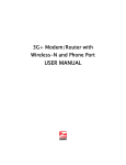
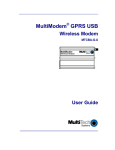
The LAN-Cell 2 is the most advanced and secure way to provide cellular Internet
access to Ethernet-based devices. Use the LAN-Cell 2 to provide access to remote
equipment, gather telemetry or other M2M data, establish Internet service in
temporary locations, or back-up Internet service with a cellular connection.
Beyond cellular Internet connectivity, the LAN-Cell 2 provides an integrated fullfeatured IP router, 802.11 a/b/g access point, automatic WAN fail-over, policy-based
routing, bandwidth management, and special features to intelligently control your
cellular data costs and maximize up-time. Security features include a built-in IPsec
VPN client & server, 3DES & AES encryption, X.509 certificates, DMZ and VLAN
support, an SPI firewall and NAT/PAT services. The LAN-Cell’s platform independent
embedded web configurator makes setup easy and allows you to manage the
LAN-Cell from the LAN or remotely over the Internet with no software on your PC.
Figure 1: Typical LAN-Cell 2 Network Configuration
This guide covers the initial configuration needed to start using the LAN-Cell 2.
Please see the User’s Guide for more information on all of the LAN-Cell 2’s features.
Also refer to the included LAN-Cell 2 Documentation CD and Proxicast’s Support
Web Site (http://support.proxicast.com) for technical notes, application configuration
examples and knowledgebase articles.
1
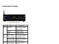
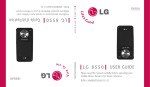
II. Hardware Indicators & Connections
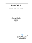
Figure 2: LAN-Cell 2 Front Panel
LABEL
PWR
LAN /
DMZ 1-4
WAN
AUX
WLAN
CELL
LED STATE
DESCRIPTION
Flashing Green
Power-on Self Test is in progress.
(approximately 60 sec)
Solid Green
Powered on and running.
Solid Red
Supplied voltage is too low.
Solid Green (10 Mbps)
Solid Orange (100 Mbps)
Link Status on the corresponding
wired LAN/DMZ Ethernet ports.
Flashing Green (10 Mbps)
Flashing Orange (100 Mbps)
Data activity on the corresponding
LAN/DMZ Ethernet ports.
Solid Green (10 Mbps)
Solid Orange (100 Mbps)
Link Status on the wired WAN
Ethernet port.
Flashing Green (10 Mbps)
Flashing Orange (100 Mbps)
Data activity on the wired WAN
Ethernet port.
Solid Green
Dial-Backup port is Enabled &
connected to a remote server.
Flashing Green
Data activity on the Dial-Backup port.
Solid Green
The LAN-Cell’s internal WLAN
Access Point is Enabled.
Flashing Green
Data activity between the LAN-Cell
and a WLAN client device.
Flashing Green
3G Cellular Card is initializing OR not
registered on the carrier network OR
there is no compatible cellular service
available at the current location.
Solid Green
3G Cellular Card is ready to make a
connection.
Solid Orange
3G Cellular Card has made a
connection to the carrier’s network.
Flashing Orange
Data activity between the LAN-Cell
and the 3G Cellular carrier’s network.
Flashing Green/Orange
Signal strength or quality is Poor.
Connections may be unreliable.
2
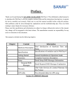
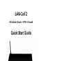
Figure 3: LAN-Cell 2 Rear Panel
LABEL
DESCRIPTION
PWR
Connect the included 12V DC power adapter to this power jack.
Reset
To erase all user-entered settings, press & hold the reset button
with a small object such as a paperclip for approximately 10
seconds until the PWR LED begins to flash. This returns the
LAN-Cell to its factory default settings (LAN IP = 192.168.1.1
Password = 1234).
LAN/DMZ 1-4
Connect computer equipment to these ports with Ethernet
cables. These ports are auto-negotiating (can connect at 10 or
100 Mbps) and auto-sensing (automatically adjust to the type of
Ethernet cable you use, straight-through or crossover). Set the
ports as LAN or DMZ in the web configurator.
WAN
Connect a cable/DSL modem or other 10/100 Ethernet-based
WAN equipment to this port.
AUX
Connect an analog modem’s RS-232 interface to the AUX port
using the Black dial backup cable. The AUX port is used only to
provide modem dial-backup support for the wired WAN and
Cellular Modem interfaces. The default AUX port communication parameters are: 115200 bps, no parity, 8 data bits, 1 stop
bit, hardware flow control.
Console
Use the Blue serial cable to connect a terminal or PC-terminal
emulation program to the LAN-Cell for diagnostic access. The
default Console Port communication parameters are: 9600 bps,
no parity, 8 data bits, 1 stop bit, no flow control.
WLAN
Attach the supplied cylindrical Wi-Fi antenna to this SMA-RP
(reverse polarity) connector if you will be using the LAN-Cell’s
integrated 802.11 a/b/g/ access point. Attaching other types
of antennas (such antennas with standard SMA, TNC or
FME connectors) to this jack may damage the antennas
and/or WLAN antenna jack!
3G Card Slot
Insert an activated 3G PC-Card cellular modem into the slot on
the right side of the LAN-Cell. Always power off the LAN-Cell
before inserting or removing PC-Cards, otherwise damage
to the LAN-Cell or the PC-Card may result.
3
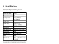
III.
LAN-Cell 2 Default Settings
The factory default settings for the LAN-Cell’s key parameters are:
LAN-Cell’s LAN IP Address
192.168.1.1
Management Access Password
1234
TCP Management Ports
HTTP (80), HTTPS (443),
Telnet (23), SSH (22)
LAN DHCP Server
On
LAN DHCP Settings
192.168.1.33 to .160
Subnet mask 255.255.255.0
WAN DHCP Client
On
Cellular Modem Interface
Enabled, Dial on Demand, Cell-Sentry Off
WLAN Access Point
Disabled
WLAN Country Code
255 – U.S. / North America
Firewall
Enabled
Serial Console Port
9600 bps, no parity, 8 data bits, 1 stop bit,
no flow control.
Press the Reset button for 10 seconds to return the LAN-Cell to these settings.
IV.
Using the Internal Web Configurator
NOTE: You can use either the embedded web configurator or the System
Management Terminal to access and configure the LAN-Cell. This Quick Start
Guide shows you how to use the web configurator only. See the User’s Guide
for more information on all of the LAN-Cell’s configuration options.
Click the web configurator’s help icon
for screen-specific assistance.
Step 1: Enter http://192.168.1.1 as the web site address in your browser.
Step 2: The default password (“1234”) is already in the password field (in nonreadable format). Click Login to proceed to the Change Password screen.
Step 3: It is highly recommended that you change the default password! Enter
a new password, retype it to confirm and click Apply. The LAN-Cell will then
request that you log in again. Alternatively, click Ignore to proceed if you do not
want to change the password.
Step 4: Click OK to create a unique security certificate for this LAN-Cell or click
Ignore to later import your own certificate.
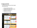
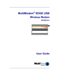
Step 5: You should now see the LAN-Cell’s Home (System Status) screen
(see Figure 4).
4
V. Configuring the LAN-Cell 2
The Home screen provides a snapshot look at your LAN-Cell’s configuration
and operational status including:
1.
2.
3.
4.
5.
Overall system information & resource utilization
The operational status and IP address of each network interface
Detailed status of the Cellular Modem interface
Detailed status of the Wi-Fi access point
A list of the latest system alert messages
Figure 4: LAN-Cell 2 Home Screen
The expandable menus in the left-side frame provide access to the
LAN-Cell’s advanced configuration screens. In addition, many of the Home
screen field labels are “hot linked” to their corresponding configuration
pages. Some items you may need to configure for your specific application
include:
Network > LAN
Use the screens in this area to change the LAN-Cell’s IP
address and its DHCP server settings.
Network > WAN
The screens in this area configure the Wired and Cellular
WAN settings. Refer to your ISP’s documentation
regarding their requirements.
Wireless > Cellular After activating the PC-Card modem with your cellular
carrier and inserting it into the PC-Card slot, you must
also configure the 3G interface using this screen (see
below). The PC-Card modem must complete initialization
and registration on your carrier’s network – this process
may take up to several minutes each time the PC-Card is
reset. The Connection Status on the Home Screen will
show READY when dialing attempts can commence.
5
Wireless > Wi-Fi
The LAN-Cell’s integrated 802.11 a/b/g access point is
DISABLED by default. Use the screens in this area to
enable and configure your Wi-Fi settings.
Security > Firewall
You can use the LAN-Cell without configuring the
firewall. The LAN-Cell’s firewall is ENABLED by default
and is set to block inbound initiated packets to LAN
devices. You may need to change the default firewall
rules to suit your specific application.
Security > VPN
The LAN-Cell 2 includes a Wizard to step you through
the process of creating a basic IPSec VPN. Use the
VPN Config screens to adjust any settings as
necessary for connection to your other VPN equipment.
Advanced > DNS
Use the DDNS tab to configure a DNS hostname for
your LAN-Cell if your Cellular or WAN ISP assigns
dynamic IP addresses. You must set up an account with
one of the supported Dynamic DNS Service Providers
before configuring the LAN-Cell.
Advanced > NAT
To access devices attached to the LAN-Cell’s LAN ports
from the Internet, configure the necessary port
translation/redirections on this screen. You may also
need to change the LAN-Cell’s Remote Management
ports and VPN Rules if they conflict with your
application.
Maint > Time & Date The LAN-Cell 2 has a battery-backed real-time clock.
Set the current date & time on this screen and configure
a time-server to periodically adjust the LAN-Cell’s clock.
Consult the User’s Guide for more detailed information on how to configure
all of the LAN-Cell’s features.
Note for Wi-Fi Users:
If deploying the LAN-Cell 2 outside of North America, you must change the
firmware’s Country Code to enable the appropriate 802.11 channels for the
country of operation. Failure to change the Country Code may cause
unintended interference or prevent other 802.11 equipment from connecting
to the LAN-Cell and may violate local communication regulations. See the
Wireless LAN section of the User’s Guide for more information.
Once the LAN-Cell is functioning to your satisfaction, we strongly
recommend that you backup the device configuration to your PC.
See: Maintenance > Backup & Restore
6
VI. Setting Up 3G Cellular PC-Card Modems
Please refer to the Release Notes on the LAN-Cell Documentation CD or the
Proxicast web site for a list of the specific 3G modem cards supported by the
LAN-Cell 2 in each firmware release.
Your 3G cellular PC-Card modem may need to be activated with your cellular
service provider before it can used in the LAN-Cell 2 Follow your carrier or card
manufacturer’s instructions for activating, testing, and updating the firmware on
your 3G card using a Windows PC before attempting to use it in the LAN-Cell 2.
To configure the LAN-Cell 2 for operation on your specific cellular carrier’s
network, you will need the following information:
Parameter
Your Cellular Carrier’s Settings
†
APN
Authorization Type
Username
Password
ISP Access #
(#777 for CDMA, *99# for GSM)
PIN Code‡
† APN applies only to GSM carriers. Many GSM carriers operate different APNs for different types of data service plans.
‡ The 4 digit PIN code field is displayed and required only if your SIM/RUIM is locked by the carrier.
These settings are entered on the Wireless > Cellular screen (Figure 5).
7
1.
Make sure that the Cellular interface is Enabled.
2.
For GSM networks, enter the APN (Access Point Name) that was
provided by your service provider. For CDMA networks, the APN
field is not required or displayed.
3.
Select the Authentication Type used by your service provider. If it
was not given, leave the field at the default (None).
4.
If required by your network operator, also enter the User Name,
Password, and PIN code used for network access.
5.
Enter the ISP Access Phone Number provided by your carrier
(typically #777 for CDMA and *99# for GSM).
6.
To keep the Cellular WAN connected at all times, select “Always
On”, otherwise indicate how long to wait before the LAN-Cell drops
the 3G connection when no data activity is detected.
7.
For WAN IP Address Assignment, select Get Automatically from
ISP. This is the correct setting in most situations, even if your
carrier has assigned a “static” IP address to your 3G card.
8.
Click Apply, then return to the Home screen to see the 3G status.
Figure 5a: Cellular Modem Configuration Screen (GSM)
Figure 5b: Cellular Modem Configuration Screen (CDMA)
8
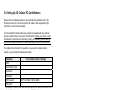
Common settings for some carriers are shown below. Contact your carrier or
Proxicast Support if settings for your carrier are not shown.
CDMA Carriers
Auth. Type
Username
Password
Verizon Wireless
NONE
{blank}
{blank}
Sprint PCS
NONE
{blank}
{blank}
Alltel
CHAP/PAP
[email protected]
alltel
Bell Mobility
CHAP/PAP
[email protected]
{voicemail
password}
Telus
PAP/CHAP
[email protected]
{11 digit ESN}
MDN is the “Mobile Directory Number” (phone #) assigned to your cellular card.
GSM Carriers
APN
Auth. Type
Username
Password
isp.cingular
CHAP/PAP
ISP@CING
ULARGPRS
.COM
CINGULAR1
AT&T Mobility
(Cingular) with
Mobile Terminated
Data Service
internet
NONE
{blank}
{blank}
T-Mobile USA
internet3.
voicestream.
com
NONE
{blank}
{blank}
Rogers AT&T
vpn.com
NONE
{blank}
{blank}
Vodaphone (UK)
Internet
CHAP/PAP
web
web
Orange (UK)
orangeinternet
PAP
{blank}
{blank}
AT&T Mobility
(Cingular)
Carrier network access parameters are subject to change.
9
VII.
Cell-Sentry™: Cellular Budget Control
The LAN-Cell 2 has a unique feature called Cell-Sentry which monitors and/or
limits the amount of traffic that passes through the cellular interface. This
feature enables you to utilize a carrier’s lower cost data service plans and
ensures that you do not exceed your plan allowance. *
At the bottom of the Wireless > Cellular screen, enable Cell-Sentry and specify
either a time-based or data-based budget for the month.
Figure 6: Example Cell-Sentry Data Budget Configuration
The LAN-Cell keeps a running total of your cellular account usage, even after
system restarts and power-cycles. Specify when the monthly counters are reset
(for example, to coincide with your monthly carrier billing cycle). You can also
specify whether or not to allow the LAN-Cell to exceed your allocated budget
and when to notify you that your budget limit is approaching.
To receive E-mails when the budget thresholds are reached, select “Alert” and
configure the LAN-Cell’s alert E-mail feature on the Logs > Log Settings
screen.
Figure 7: Log & Alert E-Mail Configuration
* Actual usage statistics on the carrier’s network may differ from the LAN-Cell’s counters.
Set your budget limits lower than the maximum allowed on your plan.
10
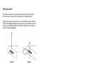
VIII. Card-Lock™
The LAN-Cell 2’s Card-Lock system provides a mechanism for securing the
PC-Card modem to prevent it from coming loose in mobile applications.
Simply insert a cable-tie through the two Card-Lock brackets above and below
the PC-Card slot (Figure 8) leaving enough slack to accommodate the portion of
the PC-Card that extends outside of the LAN-Cell. Rotate the loop toward the
front of the LAN-Cell (Figure 9).
Figure 8
Figure 9
Insert the PC-Card modem fully into the LAN-Cell, keeping the cable-tie loop
toward the front of the unit (Figure 10). Once the PC-Card is inserted, slide the
loop over the protruding end of the card and pull the bottom of the cable-tie
straight down to tighten the loop against the card. Then bring the bottom of the
cable-tie up to secure it with the cable-tie lock, tightening it against the PC-Card
(Figure 11).
You may also wish to lock the PC-Card’s external antenna “pig-tail” cable inside
the cable-tie loop to minimize movement of the antenna cable.
Figure 10
11
Figure 11
Troubleshooting
PROBLEM
CORRECTIVE ACTION
None of the
LEDs turn on
Ensure that the correct power adapter is connected to the
LAN-Cell and have plugged it into an appropriate power
source. If the LEDs still do not turn on, there may be a
hardware problem – contact your vendor.
Cannot access
the LAN-Cell
from a PC on
the LAN
Check the cable connection between your computer (or
hub) and the LAN-Cell. Check that the corresponding
LAN port LED is ON.
Confirm that your PC’s default gateway is the LAN-Cell’s
IP address.
Confirm that any other network interfaces on the PC (such
as Wi-Fi) are disabled. You cannot use Wi-Fi for the initial
configuration of the LAN-Cell, as the internal Wi-Fi Access
Point is disabled by default.
Configure your PC to receive its IP settings via DHCP.
Cannot ping any
computer on the
LAN
If the LAN LEDs are off, check the cable connections.
Cellular modem
card does not
initialize
Confirm that the PC-Card modem has been activated by
your cellular carrier. Follow their instructions for activating
the card using a Windows PC.
(Cell LED
continues to
flash)
If your cellular modem card requires a SIM/RUIM card,
ensure that it is properly inserted.
Verify that the IP address and subnet of the LAN-Cell is in
the same range as the computers on the LAN and that the
LAN-Cell is the default gateway for all LAN devices.
Network registration may take several minutes.
Confirm that your 3G cellular modem card is supported by
the LAN-Cell’s firmware version (see the Release Notes).
12
Troubleshooting
PROBLEM
Cannot make (or
maintain) a
cellular data
connection when
cellular signal is
present
(i.e. no Cellular
WAN IP address)
Wrong type of
WAN IP address
is assigned
(i.e. dynamic
instead of static
or private instead
of public)
Cellular Signal
Strength is low
CORRECTIVE ACTION
Confirm that the Cellular modem’s APN, Username,
Password, Authentication Type, PIN and ISP Access
Phone Number settings are correct for your carrier.
Confirm that the 3G cellular modem card has been
provisioned with the correct type of Internet access data
service by your carrier.
Confirm that the 3G cellular modem card has been
activated by your carrier and/or by using a Windows PC.
The IP address assigned to the LAN-Cell’s WAN
interfaces is controlled by your ISP. Confirm that your
account has been provisioned for the proper type of IP
address and that your connection parameters match those
required by your service provider.
For most 3G carriers, the correct setting is
“Get Automatically from ISP” even if your card has a
“static” IP address assigned by the carrier.
Check that the proper 3G antenna is securely attached to
the 3G card and/or LAN-Cell’s external 3G antenna jack.
Cellular data connections may be unreliable if the signal
strength/quality is reported as Poor.
Move the LAN-Cell to a location when the carrier’s signal
is stronger or use a higher-gain antenna or amplifier.
Cannot get a
WAN IP address
from the Wired
WAN ISP
The WAN IP address is provided after the ISP verifies the
MAC address, host name or User ID. Confirm the
verification method used by your ISP and configure the
corresponding fields. Try using PAP-only authentication
with no PPP compression.
Check the LAN-Cell’s connection to the wired WAN
(cable/DSL modem). Check whether your Ethernet WAN
connection requires a crossover or straight cable.
Check the settings in the WAN screens, especially the
routing priority and fail-over/load balancing parameters.
13
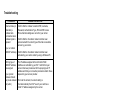
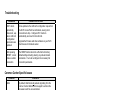
Troubleshooting
PROBLEM
CORRECTIVE ACTION
Wi-Fi clients
periodically
disconnect, esp.
when LAN-Cell
configuration
parameters are
updated
Some updates to the LAN-Cell’s configuration require that
the Wi-Fi Access Point be reinitialized, causing client
connections to drop. Configure Wi-Fi clients to
automatically reconnect to the LAN-Cell.
After pressing
RESET, cannot
make a cellular
connection
The RESET button returns the LAN-Cell to its factory
default settings including clearing any cellular modem
parameters. You must reconfigure the necessary 3G
connection parameters.
Upgrade the firmware and driver software on your Wi-Fi
client devices to the latest version.
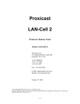
Common Carrier-Specific Issues
CARRIER
Alltel
COMMENT
By default, Alltel blocks all packets originating from the
Internet. Contact Alltel technical support to unblock the
necessary ports for your application.
Alltel’s default gateways do not respond to ICMP (ping)
packets. Do not select the “Ping Default Gateway” option
under Cellular Connectivity Check; select another public IP
address or DNS name.
AT&T Mobility
The APN “isp.cingular” blocks all packets originating from
the Internet. If you must access the LAN-Cell or other
equipment remotely, request that AT&T give you access to
the “internet” APN (mobile terminated data service).
Sprint PCS
Sprint blocks access to ports 80 & 5000 (and perhaps
others) from Internet addresses. Move your servers to a
different port number or use the LAN-Cell’s NAT Port
Forwarding & Redirection feature to map to open ports.
Verizon Wireless
Verizon Wireless’ default gateways do not respond to ICMP
(ping) packets. Do not select the “Ping Default Gateway”
option under Cellular Connectivity Check; select another
public IP address or DNS name.
Also see our online Knowledge Base at http://support.proxicast.com for more
troubleshooting tips, documentation, TechNotes and configuration examples.
14
The REALLY QUICK Start Guide
1.
2.
3.
4.
5.
6.
7.
8.
Power off the LAN-Cell 2. Insert an activated 3G Cellular PC-Card modem.
Power on the LAN-Cell 2. Wait 60 sec. for the PWR LED to stop flashing.
Connect a DHCP-enabled PC to one of the LAN ports.
Browse to http://192.168.1.1 Password is: 1234
Select Wireless > Cellular from the left side menu on the Home screen.
If required, enter your APN, PIN, Username, and Password.
Enter your ISP access phone number (#777 for CDMA, *99# for GSM) and
enable “Always On”.
Click “Apply”.
The LAN-Cell will now attempt to initialize your 3G PC-Card modem and make a
connection to the Internet. Return to the Home screen to check the connection
status. If the card fails to fully initialize, power-cycle the LAN-Cell to reset the 3G
modem card. The LAN-Cell will make a cellular connection once it restarts.
312 Sunnyfield Drive, Suite 200
Glenshaw, PA 15116-1936
1-877-77PROXI (1-877-777-7694)
1-412-213-2477 (outside USA)
www.proxicast.com
[email protected]
© Copyright 2000 - 2008. Proxicast, LLC. All rights reserved.
Proxicast is a registered trademark and LAN-Cell, Cell-Sentry, Card-Guard and CardLock are trademarks of Proxicast LLC. All other trademarks/servicemarks mentioned
are the property of their respective owners.
15