1
CONTENTS
Preface
Intended Use Statement …………………………………………………………………………….. 1
Safety Summary ……………………………………………………………………………………… 1
Specifications – Analysis Enclosure: General …………………………………………………….. 4
Specifications – Probe/Sample Handling Enclosure: General ..………………………………… 5
Customer Service, Technical Assistance and Field Service ………..………………………….. 6
Returning Parts to the Factory………………………………………………………………………. 6
Training ………………………………………………………………………………………………... 7
1.
Introduction......................................................................... 1–1
1.1
1.2
1.3
1.3.1
1.3.2
1.3.3
1.3.4
Overview..........................................................................................................................1–1
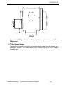
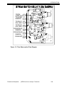
Time Shared Option.........................................................................................................1–3
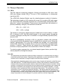
Theory of Operation.........................................................................................................1–5
NOx.................................................................................................................................. 1–5
CO ................................................................................................................................... 1–5
O2 .................................................................................................................................... 1–6
SO2.................................................................................................................................. 1–7
2.
Detector Methodologies..................................................... 2–1
2.1
2.1.1
2.1.2
2.1.3
2.2
2.3
Non-Dispersive Infrared (NDIR).......................................................................................2–1
Interference Filter Correlation Method ............................................................................. 2–1
Opto-Pneumatic Method.................................................................................................. 2–2
Overall NDIR Method....................................................................................................... 2–4
Paramagnetic Oxygen Method ........................................................................................2–5
Electrochemical Oxygen Method .....................................................................................2–6
3.
Installation........................................................................... 3–1
3.1
3.2
3.2.1
3.3
3.3.1
3.3.2
3.3.3
3.3.4
3.3.4.1
3.3.4.2
3.3.4.3
3.3.4.4
3.3.4.5
3.3.4.6
3.3.4.7
3.3.4.8
3.3.5
3.3.5.1
3.3.5.2
3.3.5.3
Specifications...................................................................................................................3–1
Process and Calibration Gas Connection........................................................................3–5
Gas Conditioning ............................................................................................................. 3–6
Installation........................................................................................................................3–1
Location ........................................................................................................................... 3–1
Limitations........................................................................................................................ 3–1
Mounting Options............................................................................................................. 3–1
Electrical Connections ..................................................................................................... 3–1
Circular Connector Assembly Instructions.......................................................................3–2
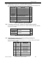
EXT I/O Interface Connector ...........................................................................................3–4
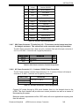
SHU #1 / #2 Interface Connector.....................................................................................3–6
COM Interface Connector................................................................................................3–1
Lan Interface Connector ..................................................................................................3–1
CPU I/O Interface Connector...........................................................................................3–1
SSU Power Connector, T/S units Only ............................................................................3–2
AC Power Connector .......................................................................................................3–2
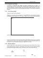
Analytical Leak Check ..................................................................................................... 3–3
Flow Indicator Method .....................................................................................................3–1
Manometer Method..........................................................................................................3–1
Troubleshooting Leaks ....................................................................................................3–3
4.
Startup and Operation........................................................ 4–1
4.1
4.2
4.2.1
4.2.2
Startup Procedure............................................................................................................4–1
Analyzer Operation .......................................................................................................... 4-1
User Interface ...................................................................................................................4-1
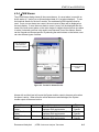
µCEM Main Window .........................................................................................................4-2
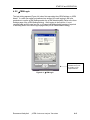
µCEM Menus ............................................................................................................... 4-4
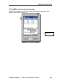
µCEM Alarms................................................................................................................... 4-6
4.2.3
4.2.4
Rosemount Analytical
µCEM Continuous Analyzer Transmitter
2