1
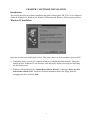
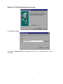
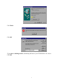
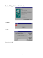
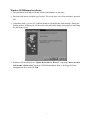
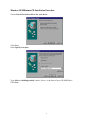
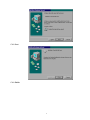
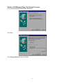
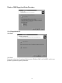
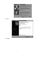
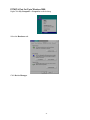
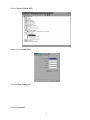
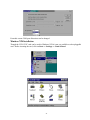
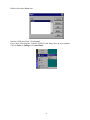
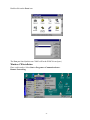
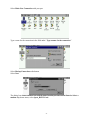
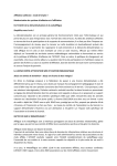
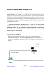
Serial Communications Boards
CYB 1232C
1-Port PCMCIA RS-232
Serial Card
USER’S MANUAL
REVISION 2.1 – OCTOBER 1999
No part of this manual may be reproduced without permission.
CyberResearch, Inc.
www.cyberresearch.com
25 Business Park Drive, Branford, CT 06405 USA
203-483-8815 (9am to 5pm EST) FAX: 203-483-9024
©1994 CBI ©1997 CyberResearch, Inc.
©Copyright 2000 CyberResearch, Inc.
All Rights Reserved.
The information in this document is subject to change without prior noticed in order to improve
reliability, design, and function and does not represent a commitment on the part of
CyberResearch, Inc.
In no event will CyberResearch, Inc. be liable for direct, indirect, special, incidental, or
consequential damages arising out of the use or inability to use the product or documentation, even if
advised of the possibility of such damages.
This document contains proprietary information protected by copyright. All rights are reserved. No
part of this manual may be reproduced by any mechanical, electronic, or other means in any form
without prior written permission of CyberResearch, Inc.
TRADEMARKS
“CyberResearch” and “CYB 1232C” are trademarks of CyberResearch, Inc. Other product names
mentioned herein are used for identification purposes only and may be trademarks and/or registered
trademarks of their respective companies.
NOTICE
CyberResearch, Inc. does not authorize any CyberResearch product for use in life support systems,
medical equipment and/or devices without the written approval of the President of CyberResearch,
Inc. Life support devices and systems are devices or systems which are intended for surgical
implantation into the body, OR support sustain life and whose failure to perform can be reasonably
expected to result in injury. Other medical equipment includes devices used for monitoring, data
acquisition, modification, or notification purposes in relation to life support, life sustaining, or
components required, are not subject to the testing required, and are not submitted to and diagnosis
of humans.
Table Of Contents
CHAPTER 1 HARDWARE GUIDE...............................................................1
Introduction....................................................................................................1
CYB 1232C Card Features. ...........................................................................1
Configuring PCMCIA Cards. .........................................................................1
CHAPTER 2 INSTALLING IN YOUR COMPUTER...................................2
CHAPTER 3 SOFTWARE INSTALLATION ...............................................3
Introduction....................................................................................................3
Windows 95 Installation.................................................................................3
Windows 95 CD-ROM Installation Procedure................................................4
Windows 95 Floppy Disk Installation Procedure ............................................6
Windows 98/Millennium Installation .............................................................7
Windows 98/Millennium CD Installation Procedure.......................................8
Windows 98/Millennium Floppy Installation Procedure ...............................10
PCMCIA Card Set-Up in Windows 95/ 98/Millennium ................................12
PCMCIA Port Set-Up in Windows 95/98/Millennium ..................................13
Windows 2000 Installation...........................................................................16
Windows 2000 CD-ROM Installation Procedure ..........................................17
Windows 2000 Floppy Installation Procedure ..............................................20
PCMCIA Port Set-Up in Windows 2000 ......................................................22
Windows NT4 Installation............................................................................24
Windows CE Installation..............................................................................26
CHAPTER 4 RS-232 PINOUTS AND PORT CABLING...........................29
Introduction..................................................................................................29
The RS-232 Standard. ..................................................................................29
Serial Port Pin Outs. .....................................................................................29
9-Pin D Serial Port RS-232 Cables. ..............................................................30
9-Pin D Serial Port Connection to Another PC. ............................................30
9-Pin D Serial Port to a Modem....................................................................31
9-Pin D Serial Port Loop Back Connector. ...................................................31
CHAPTER 1 HARDWARE GUIDE
Introduction
This chapter details the specifications of the PCMCIA 1 Port RS-232 Serial card.
PCMCIA 1-Port RS-232 Card Features
* One RS-232 Serial port.
* Reliable communications up to 50 feet, 15m, and beyond.
* 100% 16C550 PC Compatible serial port up to 115200 Baud.
16950 Compatible FIFO provides 16-byte input and 16-byte output buffer on each port.
* Full modem control TXD, RXD, DSR DCD, DTR. RTS, CTS, and RI signals.
* Fully double buffered for reliable asynchronous operation.
High speed integrated circuitry ensures operation with fast PC’s, e.g., 600 MHz Pentium III.
* Fully Plug and Play.
* Hot Pluggable.
Dimensions:
I/O Connection:
Serial Port:
Weight:
2 x 3.3 in, 85x55 mm
9-pin Male D type.
16g
Configuring PCMCIA Cards
PCMCIA cards, by definition, require no hardware configuration and can be installed “directly from
the box.”
1
CHAPTER 2 INSTALLING IN YOUR COMPUTER
This card is “hot plug” compatible it may be inserted into your PCMCIA type 2 slot when the
machine is either off or powered on. Please refer to your machine user guide for detailed instructions
on inserting a PC card.
2
CHAPTER 3 SOFTWARE INSTALLATION
Introduction
This section describes the software installation procedure allowing the CYB 1232C to be configured
within the Windows 95, Windows 98, Windows Millennium and Windows 2000 operating systems.
Windows 95 Installation
•
Insert the card into an available type2 socket. This can be done even if the machine is powered ON.
•
If installing from a “power off” condition Windows 95 should then load normally. During the
booting process, Windows 95 will detect the card and briefly display a message box indicating
the detection process.
•
Windows will then display the “Update Device Driver Wizard,” requesting “insert any disk
which came with the card.” Insert the CD-ROM installation disk or the floppy disk into
an appropriate drive and click Next.
3
Windows 95 CD-ROM Installation Procedure
Click Other Locations.
Type <drive>:\diskimg\sswin9x, substituting the letter of your CD-ROM drive for <drive>
Click OK.
4
Click Finish.
Click OK.
*Type<drive>:\diskimg\sswin9x, substituting the letter of your CD-ROM drive for <drive>
Click OK.
5
Windows 95 Floppy Disk Installation Procedure
Click Finish.
Click OK.
Type a:\, then click OK.
6
Windows 98/Millenium Installation
•
The installation for Windows 98 and Windows Millennium are the same.
•
Insert the card into an available type2 socket. This can be done even if the machine is powered
ON.
•
If installing from a “power off” condition Windows 98 should then load normally. During the
booting process, Windows 98 will detect the card and briefly display a message box indicating
the detection process.
•
Windows will then display the “Update Device Driver Wizard,” requesting “insert any disk
which came with the card.” Insert the CD-ROM installation disk or the floppy disk into
an appropriate drive and click Next.
7
Windows 98/Millenium CD Installation Procedure
Choose Search for the best driver for your device.
Click Next.
Select Specify a location
Type <Drive>:\diskimg\sswin9x\, where <Drive> is the letter of your CD-ROM Drive.
Click Next.
8
Click Next.
Click Finish.
9
Windows 98/Millenium Floppy Installation Procedure
Choose Search for the best driver for your device.
Click Next.
Select Floppy disk drives, then click Next.
10
Click Next.
Click Finish.
11
PCMCIA Card Set-Up in Windows 95/ 98/Millennium
Right-click My Computer -> Properties on the desktop.
Click on the Device Manager tab.
Under Multi-function adapters double-click on PCMCIA 1 Port 422 Card.
12
Click on the Serial Solutions tab.
The Serial Solutions tab allows modification of any user controlled features for the card.
PCMCIA Port Set-Up in Windows 95/98/Millennium
Right-click My Computer -> Properties on the desktop.
13
Under Ports (COM &LPT) double-click on PCMCIA RS-422 PORT (COM*).
(* is the number allocated to the port.)
Click on the Port Settings tab.
Settings available in this window are:
Baud Rate.
Data Bits.
Parity.
Stop Bits.
Flow Control.
Change to suit remote device.
14
Restore Defaults: When clicked, this will reset the selected port to the default values of:
Baud Rate:
Data Bits:
Parity:
Stop Bits:
Flow Control:
9600
8
None
1
Xon / Xoff
Maximum Baud Rate Setting
These settings allow access to the faster data rates available on this card. The faster rates are not
enabled by default for compatibility purposes. The faster data rates are only available directly from
your application if it uses the standard Windows dialogue for serial port settings.
Baud Rate Multiplier
This enables applications that do not use the standard Windows serial port configuration dialogue to
access the faster data rates, e.g., with this option enabled, an application which selects 115,200 baud
will actually set the hardware to the fastest possible rate of 921,600 baud. In other words the baud
rate is multiplied by a factor of 8.
15
Windows 2000 Installation
•
Insert the card into an available type2 socket. This can be done even if the machine is powered
ON.
•
If installing from a “power off” condition Windows 2000 should then load normally. During the
booting process, Windows 2000 will detect the card and briefly display a message box indicating
the detection process.
•
Windows will then display the “Found New Hardware Wizard,” requesting “insert any disk
which came with the card.” Insert the CD-ROM installation disk or the floppy disk into
an appropriate drive and click Next.
16
Select Search for a suitable driver for my device.
Click Next.
Windows 2000 CD-ROM Installation Procedure
Select Specify a location.
Click Next.
17
Type <Drive>:\diskimg\sswin2k\, where <Drive> is the letter of your CD-ROM Drive.
Click OK.
Click Next.
18
Please note, at the time of creation of this document, Windows2000 is still in BETA, and it is not
possible to get drivers signed by Microsoft.
Click Yes.
Click Finish.
19
Windows 2000 Floppy Installation Procedure
Select Floppy disk drives.
Click Next.
Click Next.
Please note, at the time of creation of this document, Windows 2000 is still in BETA, and it is not
possible to get drivers signed by Microsoft.
20
Click Yes.
Click Finish.
21
PCMCIA Port Set-Up in Windows 2000
Right Click My Computer -> Properties on the desktop.
Select the Hardware tab.
Click Device Manager.
22
Click on Ports (COM & LPT).
Double-click on Serial Port.
Select the Port Settings tab.
Click on Advanced.
23
From this screen COM port allocations can be changed.
Windows NT4 Installation
Though the CYB 1232C card can be used in Windows NT4 it is not yet available as a hot-pluggable
card. Before inserting the card, click on Start => Settings => Control Panel.
24
Double-click on the Ports icon.
Note the COM ports listed. Click Cancel.
Power down your computer, insert the PCMCIA card, then power up your computer.
Click on Start => Settings => Control Panel.
25
Double-click on the Ports icon.
The New port listed (in this case COM2 will be the PCMCIA card port.)
Windows CE Installation
Place card in socket. Select Start=>Programs=>Communications=>
Remote Networking.
26
Select Make New Connection with your pen.
Type a name for the connection in the field under “Type a name for the connection.”
Select Dial up Connection radio button.
Select Next.
The dialog box shows a modem icon with the name from the previous screen. From the Select a
modem drop-down menu, select 1port_RS232 Card.
27
Click the Configure button.
In the Device Properties dialog box, set the following:
Baud Rate
Data Bits
Parity
Stop Bits
Flow Control
9600
8
None
1
None
28
CHAPTER 4 RS-232 PINOUTS AND PORT CABLING
Introduction
This chapter gives details of the 9- and 25-pin RS-232 pin outs cabling and connections, with
information on how to connect the serial ports of two PCs and how to make a self-test loop back
connector.
The RS-232 Standard
RS-232 is a slow, short distance, single ended transmission system (i.e., only one wire per signal).
Typical RS-232 maximum cable length is 50 feet with a maximum data rate of 20K bits per second.
Figure 4-1. RS-232 Point To Point Connection
TTL D
R
Ground
TTL
Ground
RS-232C Standard
1 Driver 1 Receiver
Line Length
Max Data Rate
50 Feet = 15m
20 Kbits/sec
Serial Port Pin Outs
The pinouts of the 9- and 25-pin Male D connectors are given below.
Figure 4-2. Serial Port RS-232 Pin Outs
9-Pin Connector:
PIN 6 - DATA SET READY (DSR)
PIN 7 - REQUEST TO SEND (RTS)
PIN 8 - CLEAR TO SEND (CTS)
PIN 9 - RING INDICATOR (RI)
PIN 1 - DATA CARRIER DETECT (DCD)
PIN 2 - RECEIVED DATA (RXD)
PIN 3 - TRANSMITTED DATA (TXD)
PIN 4 - DATA TERMINAL READY (DTR)
PIN 5 - GROUND (GND)
25-Pin Connector:
PIN 20 - RING INDICATOR (RI)
PIN 2 -TRANSMITTED DATA (TXD)
PIN 3 -RECEIVED DATA (RXD)
PIN 4 - REQUEST TO SEND (RTS)
PIN 5 - CLEAR TO SEND (CTS)
PIN 6 - DATA SET READY (DSR)
PIN 7 - GROUND (GND)
PIN 8 - DATA CARRIER DETECT (DCD)
PIN 22 - DATA TERMINAL READY (DTR)
29
9-Pin D Serial Port RS-232 Cables
To connect to the AT style RS-232 Serial Port like those found on the CYB 1232C card you will
need a cable terminating in a 9-way female D connector. It is sound practice to use cables with
screws fitted that will allow you to fasten the cable securely to the PC card.
In general, you will need to make up a “cross over cable” to correctly interface the PC to the RS-232
port of another computer or device. The cross over cable is simply to ensure that the right signals
going out of one RS-232 port go into the appropriate lines of the other RS-232 port.
9-Pin D Serial Port Connection to Another PC
Suppose we want to connect the AT style 9-pin D Serial Port to the serial port of another IBM-style
PC. See Figure 4-3.
1)
Connect the earth lines.
Line 5 of Serial Port 2 to lines 1 & 7 of the other PC.
This gives the two devices a common earth level.
2)
Connect the Transmit and Receive lines together.
Line 3, TXD Port 2 goes to line 3, RXD of the other PC.
Line 2, RXD Port 2 goes to line 2, TXD of the other PC.
This allows each to receive data transmitted by the other.
3)
Connect the Port 2 DTR line, pin 4 to the other PC DCD pin 8 and CTS pin 5, lines.
Also, connect up the other PC DTR line, pin 20 to the Port 2 DCD pin 1 and CTS pin 8, lines.
This allows the receiving device to signal when it can no longer accept data. The receiving
device sets DTR false when it is unable to receive any more data. The sending device reads
DTR on its CTS and DCD pins. It should stop sending when CTS goes false.
4)
Connect the Port 2 RTS line, pin 7, to the other PC DSR line, pin 6. Also, connect the other
PC RTS line, pin 4, to the Port 2 DSR line, pin 6.
This RTS line is used to let the other device know that it is ready for data exchange.
30
Figure 4-3. 9-Pin D Serial Port to Other PC Cable
AT SERIAL PORT Side
9-PIN D CONNECTOR
Other PC SERIAL PORT Side.
9-PIN D CONNECTOR
SCHEMATIC REPRESENTATION:
5
3
2
7
6
4
8
1
5
2
3
6
7
1
8
4
ACTUAL REPRESENTATION:
1
5
6
9
2
4
8
7
3
3
7
8
4
2
9
6
5
1
9-PIN D CONNECTOR
25-PIN D CONNECTOR
SCHEMATIC REPRESENTATION
5
3
2
7
6
4
8
1
ACTUAL REPRESENTATION
9-Pin D Serial Port to a Modem
If you are connecting a MODEM to a 9-pin D Serial Port then you will not need a cross over cable
and a straight through cable connected as the 9- to 25-pin adapter given in Figure 4-5.
9-Pin D Serial Port Loop Back Connector
A loop back connector can be used to echo RS-232 data transmitted by a serial port back into its own
RS-232 receiver. In this way, the function of the serial port can be tested.
For an AT style Serial Port use the female 9-way connector wired as in Figure 4-4.
31
Figure 4-4. 9-Pin D Serial Loop Back Connector
9-PIN D CONNECTOR
25-PIN D CONNECTOR
SCHEMATIC REPRESENTATION:
2
3
3
2
7
8
6
1
4
4
5
6
8
20
ACTUAL REPRESENTATION:
32
Figure 4-5. 9- To 25-Way Adapter
This adapter cable makes the AT style 9-pin serial port look like the standard PC 25-pin serial port.
It is not a cross over cable.
9-Pin AT SERIAL PORT
9-Pin Female D Connector
25-Pin PC SERIAL PORT
25-Pin Male D Connector
SCHEMATIC REPRESENTATION:
5
1
2
3
4
6
7
8
9
ACTUAL REPRESENTATION:
33