1
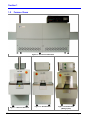
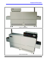
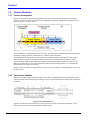
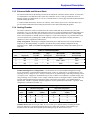
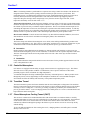
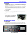
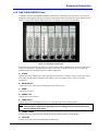
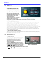
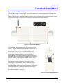
Section 1
FURNACE EQUIPMENT
1.1
Furnace Description
The LA-306 is a compact, near-infrared, conveyor belt furnace for laboratory and general purpose thermal
processing in the range of 100-980 ⁰C in a controlled atmosphere, free of outside contamination. Process gas
may be CDA, N2 or another inert gas. Dual gas furnaces may use Nitrogen and a second gas such as Forming
Gas (pre-mixed N2/H2) or another type of reducing gas injected into the heating chamber.
Figure 1-1 Furnace Front Elevation
The LA-306 furnace transports product on a 150 mm (6-inch)
wide belt. In the standard design the chamber clearance above
the belt is 50 mm (2 inches). Optionally the furnace can be
ordered with 25 mm (1-inch) or 100 mm (4-inch) vertical
clearance above belt. LA-306 furnaces feature a hermetically
sealed heating chamber permitting control of the furnace
chamber process environment. Baffle sections before and after
the heating section contain curtains that hang down to just above
the belt to further isolate the furnace chamber from the room
atmosphere and from the cooling section.
The LA-306 can process substrates, wafers, PCBs, metal,
ceramic, glass or polycarbonate parts for electronic package
sealing, thermo-setting polymer curing, reflow soldering,
hybrid/thick film firing, brazing, annealing, tempering and metal
sintering applications, or almost any kind of general thermal
processing requiring precision temperature control in a
controlled atmosphere environment.
Figure 1-2 Furnace Entrance Elevation
675-110306
1-1
Section 1
1.2
Furnace Views
Figure 1-3 Furnace Front Elevation
Figure 1-4 Entrance Elevation
1-2
Figure 1-5 Exit Elevation
Figure 1-6 Exit Elevation
(Mixing Option)
LA-306 Operation & Theory
Equipment Description
Figure 1-7 Rear Elevation
Figure 1-8 Top Front View
676-110306
1-3
Section 1
1.3
Furnace Elements
1.3.1 Furnace Arrangement
Parts are carried from the load station through the heating and cooling sections of the furnace to the unload
station on a 152 mm (6-inch) wide belt driven by an adjustable speed motor. Maximum vertical parts clearance
inside the furnace is 50 mm (2 inches).
Figure 1-9 Process Sections
Process atmosphere is controlled much like a clean room: pressurized gas is pushed through the heating chamber
insulation providing a pre-heated, laminar flow for a uniform, stable atmosphere.
The heating chamber is divided into 3 zones separated by insulation dividers so that adjacent zones can have
different setpoint temperatures if required. Control starts with K-type thermocouples in each zone quickly
sensing changing conditions and feeding these signals to individual digital PID controllers for each zone. The
PID loop controllers drive arrays of IR quartz heating lamps inside the heating chamber so as to maintain the
desired temperature setpoint in each zone.
Product cooling is by radiant cooling and CDA or N2 gas convective cooling in an enclosed tunnel, with exterior
fan heat removal.
1.3.2 The Process Chamber
The process chamber contains an entrance baffle with an eductor equipped exhaust stack, an IR heating section,
a transition tunnel between the heating and cooling sections, and a closed atmosphere cooling tunnel, arranged as
shown here:
Figure 1-10 Furnace Internals
Together, the individual sections function as a unit to provide a carefully controlled gas atmosphere, precise
temperature profile and two-stage controlled atmosphere cooling.
1-4
LA-306 Operation & Theory
Equipment Description
1.3.3 Entrance Baffle and Exhaust Stack
The entrance baffle isolates the heating section from the ambient air outside the furnace entrance. It is housed in
a welded stainless steel shell lined with ceramic fiber insulation. An N2 or CDA gas curtain and a series of
hanging stainless steel baffle plates serve to act as a thermal barrier as well as purge the baffle and block ambient
air from entering the furnace.
A venturi-assisted exhaust stack, known as an “eductor”, draws furnace gases across a removable drip tray to
prevent exhaust condensation from falling into the baffle section and contaminating the product.
1.3.4 Heating Chamber
The furnace chamber is similar in construction to the entrance baffle and may be hermetically sealed with
plenum box covers over the lamp ends. Inside this section, arrays of tungsten filament quartz heating lamp tubes
located above and below the belt, generate intense near-wave (sometimes called “short-wave”) infrared light
with a color temperature of 2500 K (peak wave length of 1.16 µm). These lamps are very efficient heaters with
very fast response times, producing up to 600W per lamp at full power and capable of heating the furnace
chamber to a state of equilibrium within minutes.
Lamp Arrangement. The lamps are arranged symmetrically above and below the belt. The top and bottom
lamps may be used independently or together to provide the best possible heating configuration for any
particular process. Table 1-1 Furnace Arrangement shows the distribution of lamps and available power in
each zone.
Table 1-1 Furnace Arrangement
Lamp
Spacing (mm)
Standard Furnace
Max. Available
Zone Power (W)
High Power Furnace
Max. Available
Zone Power (W)
Zone
Length (mm)
# of Lamps
Top / Btm
1
190
4/4
30
4800
4800
2
380
6/6
58
3800 – 4800*
7200
3
190
4/4
30
4800
4800
*Depends on power line voltage; 208 Vac: 3800W; 220 Vac: 4200W; 230 Vac: 4500W; 240 Vac: 4800W
Standard and High Power Configurations. LA-306 furnaces are wired in standard configuration or high
power configuration. In the standard configuration Zones 1 and 3 are wired with two (2) parallel strings, each
consisting of two (2) lamps in series. Zone 2 is wired with two (2) parallel strings, each string consisting of three
(3) lamps in series. High power models differ only in Zone 2 which is wired with three (3) parallel strings, each
string consisting of two (2) lamps in series. Lamps within the furnace are arranged as follows: Either model will
perform well throughout the design temperature range of the furnace (100-1000⁰C ), the standard model is
optimized for 100-500⁰C operation, while the high power model is optimized for 500-1000⁰C operation. Each
configuration is summarized in Table 1-2.
Table 1-2 Furnace Lamps Wiring Configuration
Standard Configuration
High Power Configuration
Zone
Strings
Top/Btm
Lamps per String
Top/Btm
Strings
Top/Btm
Lamps per String
Top/Btm
1
2
2
2
2
2
2
3
3
2
3
2
2
2
2
Chamber Process Gas. Process gas (CDA, N2 , FG or other gas) is preheated before reaching the furnace
interior by allowing it to permeate through the hot porous ceramic fiber insulation. This method of gas
distribution does not affect the temperature profile and helps keep the furnace interior clean.
676-110306
1-5
Section 1
Zones. The heating chamber is partitioned into 3 separate zones using ceramic fiber dividers. The dividers are
designed with the smallest possible opening consistent with the part parts clearance specifications. This
partitioning assures very high thermal isolation between zones. Although the heating profile across the belt is
extremely uniform, heat losses through the furnace side walls and at the belt edge supports produce a
temperature drop near the edges of the transport belt. Away from the extreme edges of the belt, overall
temperature uniformity across the belt will be ±3 ⁰C.
Temperature Measurement. Inside the furnace chamber, at the top center of each zone a type K thermocouple
measures the temperature in that zone and provides feedback to each respective zone PID controller to determine
the amount of power necessary to maintain setpoint temperatures. However useful these thermocouples are for
controlling the temperature in each zone, the actual part is exposed to three heat transfer methods. As with any
furnace, the most accurate way to determine what temperature product on the belt actually sees from these three
methods of heat is to profile the furnace with a thermocouple placed directly on the product surface.
Heat Transfer Methods. Transfer of heat in the furnace is by three different methods: Radiation, Convection
and Conduction. In order of their contribution to heating the product, these methods are:
A. Radiation
The furnace lamps emit infrared electromagnetic waves which, when striking and absorbed by product on the
belt, cause its temperature to rise. This is the way “heat lamps” and microwave ovens work, and also the way the
sun heats the Earth. The infrared radiation does not directly heat the process gas within the furnace.
B. Convection
During operation, lamp radiation heats the chamber top, bottom and side wall insulation. As the process gas
enters the furnace through the porous ceramic insulation, it is heated to near the setpoint temperature of the zone.
This flow of heated gas transfers heat to the product on the belt. This is how a hair dryer or home forced air
heating works.
C. Conduction
Lamp radiation heats the transport belt which becomes a heat source for the product supported on the belt. This
is how a hot plate heater works.
1.3.5 Controlled Atmosphere
LCI furnaces are equipped with the ability to supply constant streams of a supplied process gas. This feature
allows the user to reduce product oxidation or contamination, remove process effluents or reduce other
potentially negative effects of ambient air at high temperatures.
A controlled atmosphere also helps establish higher consistency in thermal processes. When a product travels
through the process section, slight changes in the atmospheric conditions in a non-controlled atmosphere
environment can affect the stability and consistency of the product temperature profile.
1.3.6 Transition Tunnel
The transition tunnel separates the furnace chamber from the closed atmosphere cooling tunnel. The transition
tunnel is constructed using the same materials as the furnace section to minimize thermal stresses to the product
caused by excessive cooling rates. Convective gas cooling of product is produced by the controlled flow of
process gas into this tunnel. A series of hanging stainless steel baffle plates serve to act as a thermal barrier and
help contain the furnace atmosphere.
1.3.7 Closed Atmosphere Cooling Tunnel (CACT)
This section is constructed of extruded aluminum heat sink material and is not insulated. Inside, a carefully
controlled atmosphere of CDA or N2 gas is maintained to cool the product to a safe temperature. Fans mounted
on the exterior of the CACT transfer heat to the air inside of the furnace cabinet. This cabinet air is then
exhausted by cabinet fan through an opening in the furnace top cover into the room or for removal by facility
exhaust ducting.
To prevent drafts and ambient air from entering the CACT, a hanging stainless steel baffle plate is mounted
directly to the CACT exit.
1-6
LA-306 Operation & Theory
Equipment Description
1.3.8 Cabinet Fans
Cabinet Fan. The furnace is equipped with one (1) 10-inch diameter fan mounted on the underside of the top of
the furnace cabinet. This fan exhausts heat emitted from the outside of the furnace chamber and cooling tunnel
into the room or customer installed exhaust system.
Enclosure Fan. The control enclosure is cooled by fan(s) mounted under the enclosure. These fans pull cool air
from the room into the enclosure through vents in the enclosure base. Room air flows into opening in the back
panel and across the heat sinks where the SCR’s are mounted and exhausts out the top of the rear panel door.
Cooling System Fans. The CACT cooling tunnel is cooled by fans mounted outside the top and bottom of the
tunnel. Cabinet air is forced over the cooling tunnel to remove heat transferred from the tunnel interior. This air
is evacuated via the cabinet fan.
1.3.9 Transport Belt
The LA-306 standard conveyor belt for high temperature applications is a close weave Nichrome-V belt
manufactured from high temperature wire comprised of 80% nickel and 20% chromium. This belt offers fast
heat-up times, more uniform operating temperatures and excellent mechanical stability. This belt exhibits
minimum shrinkage, growth, sag or distortion in use.
1.3.10 Motor
The transport drive motor assembly is typically mounted
near the exit of the process section. Depending upon belt
width, product mass, product number and belt speed, the
motor-sprocket may appear different than the example
shown in Figure 1-11 Transport Drive Motor.
1.4
Console Controls & Indicators
Figure 1-11 Transport Drive Motor
1.4.1 Control Console
Control of the furnace is via the control console (Figure 1-12 LA-306 Control Console) mounted over the
cooling section of the furnace. Independent control of each furnace zone is provided by type K sensing
thermocouples, located above the belt in each zone, coupled to digital temperature controllers that control the
power output of the lamps and sense alarm or alert conditions in each zone.
Figure 1-12 LA-306 Control Console
676-110306
1-7
Section 1
1.4.2 POWER Panel
A. MAIN POWER lamp
When this WHITE light is ON, the furnace is connected
to the power line.
B. CONTROLS pushbuttons with indicator
Pressing the green switch applies power to the furnace
controls, belt motor and cooling fans.
Pressing the red switch shuts off power to the furnace
and acts electrically in the same way as pushing an
EMO button.
Figure 1-13 Power Panel Controls
Between the switches is an indicator light that stays ON while the control system is ON.
C. LAMPS pushbuttons with indicator
These buttons work only when CONTROLS indicator is ON.
Pressing the green switch applies power to the lamps and SCRs.
Pressing the red switch shuts off power to the lamps and SCRs.
Between the switches is an indicator light that stays ON while the lamps and SCRs are ON.
D. COOL DOWN pushbutton with lamp
Pressing this switch begins a timed, power shut down sequence. The furnace lamps and SCRs shut down
immediately.
If the operator also presses the red CONTROLS switch, the control system shuts off, but the COOL DOWN
circuits keep the zone controllers, transport belt, and cooling fans ON to help cool the furnace until the timer
expires.
While in COOL DOWN, the blue indicator in the pushbutton is lighted until time expires.
E. COOL TIME knob
This knob sets the cool down time over a range from 1.2 minutes (fully CCW) to 120 minutes (fully CW). Set
enough cool down time so that each zone process temperature (red PV) falls below 100°C. When the timer
expires, all displays, the belt and fans shutoff automatically..
1.4.3 ENERGIZE LAMPS Panel
A. Zone Switches with Lamps
These zone selection switches turn top and bottom
heating elements in each zone ON or OFF. When a
switch is turned CW, those elements are selected to be
ON, and the switch light will turn ON. Turning a lighted
switch CCW will turn those elements OFF.
Selected zones will remain selected even when furnace
power is OFF.
Figure 1-14 Energize Lamps Controls
Note: Change zone selection only with LAMPS OFF to maximize zone selection switch life.
1-8
LA-306 Operation & Theory
Equipment Description
1.4.4 TEMPERATURE Panel
Figure 1-15 Zone Temperature Controllers
The temperature control for each zone’s heating elements is by a digital single-loop PID controller with loop
Autotune and 3 alarm functions. The controller’s closed loop temperature control system uses K-type
thermocouples for feedback and is preprogrammed to provide excellent furnace performance.
PV Display: process value or parameter type
SV Display: setpoint or parameter value
AT: flashes when Autotuning operation is ON
OUT1: lights when control output is ON
ALM1-ALM3: alert/alarm LEDs, light when ON
⁰F, ⁰C: temperature units selected
SET: press to select mode or set parameter
value
ROTATE: selects next parameter within a mode
DOWN: press to decrease displayed SV values
UP: press to increase displayed SV values
676-110306
1-9
Section 1
1.4.5 STATUS Panel
A. READY lamp
When all zones have heated to their SV setpoint values and the controllers have
reported all PV process temperatures as within temperature deviation limits, the
process READY light (green) on the STATUS panel will turn ON. The furnace is
then ready to process parts.
B. ALARMS
When lighted, these red LED indicators show what condition caused the alert or
alarm. An alert condition will only produce an audible and visual warning; an
alarm condition will produce an audible and visual warning and shut off the lamps
as well. Any alert or alarm condition will shut off the READY Lamp.
C. ZONE TEMP DEVIATION alert indicator
A zone has experienced a process temperature outside the setpoint temperature +/the ALM1 limits set in the zone controller. Factory setting is +/- 10⁰C.
D. OVER TEMPERATURE alarm indicator
A zone has experienced a process temperature higher than the ALM2 limit set in
the zone controller and the lamps have been turned OFF. Factory setting is 1005
°C.
Figure 1-16 Status Panel
and Alarm Controls
E. AIR PRESSURE LOW alert indicator (optional)
The CDA (clean, dry air) gas manifold has insufficient gas pressure, effecting operation. Setpoint mechanically
set at the factory.
F. N2 PRESSURE LOW alert indicator (optional)
The N2 (nitrogen) gas manifold has insufficient in gas pressure, effecting operation. Setpoint mechanically set
at the factory.
G. FG PRESSURE LOW alert indicator (optional)
The FG (forming gas, H2/N2 mix) gas manifold has insufficient gas pressure, effecting operation. Setpoint
mechanically set at the factory.
H. CLEAR pushbutton with lamp
This red lamp lights with any alert or alarm condition.
Pressing the button will clear all alerts and alarms and will immediately shut off the CALIBRATE function, if
active, on the TEST panel.
Persisting alert and alarm conditions will re-light the lamp, however, so it is best to correct the cause of the alert
or alarm condition before pressing the CLEAR button.
I. BUZZER
This is an audible signal of any alert or alarm condition.
SILENCE pushbutton with lamp
Press the SILENCE button to silence the buzzer. This will also turn on the SILENCE red lamp as a reminder to
the operator that the buzzer is off.
Pressing the SILENCE button again will enable the audible buzzer and turn off the SILENCE lamp.
J. SILENCE switch with red lamp
Turn the SILENCE switch CW to silence the buzzer. This will also turn the SILENCE red lamp ON as a
reminder to the operator that the buzzer is OFF.
Silencing alerts is useful when changing setpoint temperatures, calibrating the SCRs, or auto tuning a zone.
Turning the lighted SILENCE switch CCW will enable the audible buzzer and turn the SILENCE lamp OFF.
1-10
LA-306 Operation & Theory
Equipment Description
1.4.6 GAS FLOW CONTROL Panel
Atmosphere control is accomplished manually with flowmeters calibrated in liters per minute. The meters are
arranged to control gas flow into the various parts of the furnace and to control gas flow out the exhaust stack to
achieve overall gas flow balance within the furnace. See Figure 1-17 Gas Flow Control Panel
Figure 1-17 Gas Flow Control Panel
Each flowmeter is identified with a label as to specific function and is adjustable from zero flow to full scale by
means of a control knob. Turning this knob CW decreases flow; CCW increases flow. Flow is read on the
graduated scale at the mid-point of the bead. Meters supplied are:
A. STACK
Controls flow to the exhaust stack venturi. This flow has the capacity to exhaust a volume 15 times the venturi
flow setting from the furnace atmosphere (for example, 10 L/m of exhaust removes 150 L/m of furnace
atmosphere).
B. ENTR BAFFLE
Controls flow to the entrance baffle isolating the furnace from room air.
C. ZONE 1
Controls flow to zone 1.
D. ZONES 2 & 3
Controls flow to zones 2 and 3.
E. LAMP SEALS
Controls flow to the sealed lamp plenum boxes on each side of the furnace heating chamber.
Note: LA-306 furnaces equipped with a LAMP SEALS flowmeter should have at least 20 L/m
flow through the meter while operating to prevent damage to the element seals and to
avoid premature lamp failure.
F. TRANS TUNNEL
Controls flow to the transition tunnel isolating the heating chamber from the cooling chamber.
G. COOLING
Controls flow to the CACT closed atmosphere cooling tunnel.
676-110306
1-11
Section 1
1.4.7 TEST Panel
A. CALIBRATE pushbutton with
lamp
Whenever the LAMPS button is on, this
button applies 25% power directly to the
lamps selected on the ENERGIZE LAMPS
panel, allowing a reliable check for failed
lamps on the TOP LAMP STRINGS and
BOTTOM LAMP STRINGS indicators, or
to adjust the SCR line voltage settings
during SCR maintenance.
The built-in 2-minute timer, or pressing the
Figure 1-18 Test Panel
LAMPS OFF button and pressing the
CLEAR button, will end the CALIBRATE mode and return SCR control to the zone controllers.
B. TOP LAMP STRINGS indicators
A lamp “string” is 2 or 3 IR heating lamps wired in series to maximize each lamp’s efficiency. Whenever the
LAMPS button is on, furnace lamp strings T1 through T7 above the belt (“top” lamps) are continuously
monitored for lamp failure. String T1 is closest to the furnace entrance, and T7 is closest to the exit.
If the indicator is lit, the lamps in the string are fine. If unlit, the commanded power may be too low for an
accurate assessment (a situation most likely during actual operation of the furnace), one of the lamps in the string
may have failed, or the string may not be in the group of lamps selected on the ENERGIZE LAMPS panel.
For a more accurate assessment, use the CALIBRATE mode to check the lamps before running product in the
furnace or during maintenance checks.
C. BOTTOM LAMP STRINGS indicators
Similar in operation to the TOP LAMPS STRINGS above, these indicators monitor the IR heating lamp strings
below the belt (“bottom” lamps) in each zone.
1.4.8 TRANSPORT Panel
A. SPEED ADJUST
The Transport Speed Adjust knob controls the speed of
the transport belt. CW rotation increases belt speed,
CCW rotation decreases belt speed. There are
approximately 10 turns between minimum and
maximum speed settings.
To the right, a Belt Speed digital display meter shows
the belt speed in inches per minute (ipm), or millimeters
per minute (mm/m), or centimeters per minute (cm/min).
Figure 1-19 Transport Panel
The
, , and . are only used to change the
display settings and should be disabled during normal furnace operation.
The
1-12
, , and . are disabled during normal furnace operation.
LA-306 Operation & Theory