1
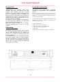
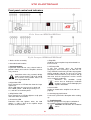
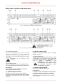
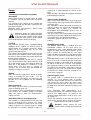
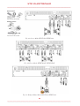
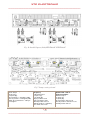
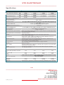
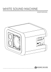
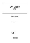
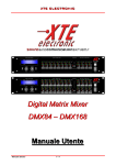
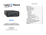
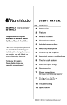
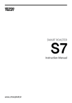
Digital Technology Series
XTDT3200 – XTDT3800
XTDT4800F – XTDT6000F
Digital Power Amplifier
User’s Manual
Important safety instructions
This symbol indicates
the presence of
important directions for
use and information
that should be given
particular attention so
as to use the product
properly.
This symbol indicates
the presence of
“dangerous voltage”
that may cause the risk
of electrical shock. Pay
the utmost attention
and proceed
cautiously.
1. Follow carefully the attached documentation
and keep it for future reference
2. Comply with the warnings
3. Store the packaging and check that all material
is in excellent conditions.
4. Do not use water near the product, do not pour
water or any other liquid on the amplifier. Do not
to use it with wet hands or feet into the water.
5. Do not use next to heat sources such as
radiators, stoves or the like.
6. Check the integrity of the mains cable. Do not
tread on the cable and do not squeeze the plug.
7. Connect the plug to a socket equipped with
grounding. Do not camper the plug. If the plug
supplied is not consistent with your socket, please
apply to an electrician for its replacement.
8. Connect to supply mains with the same voltage
as indicated on the back of the amplifier.
9. Install the amplifier in compliance with the
instructions.
10. Do not obstruct the air ducts.
11. Disconnect the appliance in case of storm and
if unused.
12. Connect according to the instructions only.
13. Do not connect input signal higher than that
indicated in the manual.
14. Do not connect the amplifier output to the
input of another channel.
15. Do not connect any output of the amplifier to
power sources such as battery, voltage supply or
outlet, regardless of the amplifier is on or off. .
16. Keep the volume controls to a minimum during
the amplifier switching on/off .
17. Do not remove the upper or lower cover: there
is a risk of electrical shock.
18. Do not try to self-repair the appliance, but
apply to qualified personnel.
19. Clean with a dry cloth only.
20. The product shall be handled by skilled
personnel in the following cases:
-
mains cable or plug damaged
Exposure of the product to rain or humidity
Some liquid entered inside the unit.
An object fell on the unit
The unit fell down and is damaged
The product does not work correctly or shows
a remarkable change of performance.
21. A careful supervision is necessary if the
product is used in the presence of children or
inexpert adults.
22. This product could produce sound levels,
which cause damage to the hearing.. Pay the
utmost attention and do not operate at high level
of volume or at an uncomfortable level for a long
time. Consult an audiometric specialist in case of
hearing loss or complaints.
Declaration of conformity
This device conforms to the requirements of
the EMC directive 89/336/EEC, amended by
92/31/EEC, and the requirements of the Low
Voltage Directive 73/23/EEC, amended by
93/68/EEC.
Standards Applied:
EN55103-1 (Emissions)
EN55103-2 (Immunity)
EN60065, Class I (Safety)
User’s liability
Radio interferences
A sample of this product has been tested and
approved to meet the requirements of the
Electromagnetic Compatibility Directive (EMC).
These requirements have been defined so as to
provide reasonable protection against dangerous
interference of electrical equipment. Whenever
this product has not been installed or handled
according to these guidelines, it might interfere
with other equipment such as radio receivers.
However, there is no guarantee that they should
not occur in a specific installation. Should this
equipment interfere with transceiver equipment
(such possibility can be checked by switching on
and off the device), the user should try to cancel
the interference by observing one or more of the
following measures:
-
Damages to the loudspeakers
Always check the peak and continuous power of
the loudspeakers.
This amplifier is extremely powerful and can be
potentially dangerous both for the loudspeakers
and for the persons.
Most loudspeakers may be easily damaged or
broken, especially by amplifiers operating in
bridge. Even if there is a gain reduction through
the attenuators on the amplifier’s front panel, it is
still possible to reach the maximum output power
if the input signal level is high enough.
Dangerous output voltage
The amplifier can generate hazardous output
voltage. Do not touch exposed cables of
loudspeakers with the amplifier in operation.
-
-
Increase the distance between the device and
the receiver.
Connect the device to a plug linked to a
different circuit with respect to the one to
which the receiver is connected.
Redirect or move the receiver’s antenna.
Make sure that the unit concerned conforms
to the EMC immunity limits (CE-labelled). All
electrical equipment sold in the EC should be
approved as for what concerns protection
against electromagnetic fields, high tension
and radio interference.
Contact qualified personnel.
Introduction____
Installation/Assembly
Congratulations on choosing power XTE
amplifiers and thanks for trusting us and our
products. Your amplifier has been carefully
planned in the smallest details, starting with every
part of its equipment till final assemblage. All
products XTE are made with the main purpose of
guaranteeing our clients’ full satisfaction, thus we
underline that the product you have chosen uses
the most advanced technology.
An improper use of the amplifier can compromise
its correct operation. Therefore we recommend
you to carefully and correctly use it.
Read this manual carefully as it contains
essential information for a safe use of your
amplifier.
All models of the XTE Digital Technology
amplifiers may be installed in a 19’’ standard rack
strand.
For the assembly 4 holes are present on the front
panel; in order to get an optimum fastening, that is
important in movable systems, additional supports
are placed on the back.
Unpacking______
Immediately inspect the package and its content
so as to check whether there are any signs of
damage. After unpacking check the product and
all parts, if you notice any damage inform your
dealer immediately.
It is advisable to save the packaging materials
even if the amplifier shows no sign of shipping
damage; you might have to return it to XTE or to
one of its dealers. Use the original package only,
which is the best way to protect the equipment
from shipping mishandling.
Pay particular attention during the installation; we
remind you that the amplifiers should not be
installed in places with:
•
•
•
•
•
•
High temperatures
Dust and excessive humidity
Presence of intense magnetic fields
Water next to the component
Vibrations
Closed spaces inhibiting a proper ventilation
Fig.1Dimensions
Front panel control and indicators
Fig.2a Front panel XTDT3200 XTDT3800
Fig.2b Front panel XTDT4800F XTDT6000F
1. Holes for the assembly
2. Standard rack handles
3. Input attenuators
A precision attenuator for every channel with 21
positions allows you to tune the amplifiers level for
every channel.
Attention: when using a mono in bridge
both level attenuators A-B (C-D) should
be set to the same position. Please set
them to position 0 dB.
7. Exp LED
It indicates that an optional expansion board has
been inserted.
8. Hi-Temp LED
It will start flashing when the dissipator
temperature starts increasing. At 60ºC the HiTemp LED will start flashing and the output power
will be gradually reduced. At 75ºC the Hi Temp
LED will remain lit and A-B (C-D) channels will go
into mute until the temperature reaches normal
level, resetting is automatic.
Attention:: this condition usually
occurs due to inadequate ventilation
clearance, please check thoroughly the
amplifier installation.
4. Signal bar LED
Every channel has a LED bar that shows the input
signal level.
Green LED shows the presence of a signal and
level -20dB, yellow – 10dB. Respectively: 0.1%,
1%, and 10% of maximum power.
9. Active LED
It lights to show that the amplifier is on and runs
properly.
5. Clip/Limiter LED
Every channel has a LED that lightens at clip point
and at the limiter intervention.
10. Starting up push button
A soft-start system limits absorption when starting
up.
6. Protection LED
Protection LED that lightens when the load
voltage is under 1 Ohm or the amplifier output
has been short-circuited.
11. Ventilation grid
Grid with sponge filters for proper ventilation of
the amplifier and to prevent dust infiltration.
Attention: Do not block the ventilation
entries.
Back panel controls and connectors
Fig.3a Back panel XTDT3200 XTDT3800
Fig.3b Back panel XTDT4800F XTDT6000F
12. Fan discharge grids
The fan of the cooling system creates an airflow
with for/back direction. The air for cooling the
amplifier is taken from the opening on the front
side and it is then discharged through the opening
on the back.
Attention: do not obstruct these
openings.
13. A.C. Mains cable
Make sure that the cable is undamaged and that
the connecting plug has ground /earth connection.
14. S.N. tag
Every unit has a tag that shows: model, power
consumption and serial number.
15. Speakon output connectors
There is a connector for every channel when
operating in stereo or parallel mode. For operating
in bridge use connector A (C) (refer to drw. page
9, 10, 11)
16. Switch for mode setting
Switch to set the usage mode (refer to drawings
page 9, 10 and 11)
17. Input connectors
Combo connectors (female XLR with 6.3mm jack)
and Europlug, a connector for every channel for
balanced or unbalanced inputs. Attention: noises
such as buzzing or disturbance on the
loudspeakers
may
occur
when
installing wiring next to dimmer, motors,
etc. Balanced connections reduce
considerably such noises.
18. HPF filter Switch ON/OFF
This switch enables the filter circuit.
19. Data port
This port is used as Input/Output connection with
the optional expansion cards such as DSP or
customised modules to equalize or to filter the
signal. For further information refer to the DSP
User’s Guide.
Usage
Connecting to the mains and power
absorption
Check whether there is enough power to supply
the amplifier. (refer to the data at the end of this
manual).
Pay attention to the voltage of the network that
should comply with the directions reported on the
back of the amplifier.
Maximum power consumption is limited solely
through the internal fuses
Attention: before any audio connection
keep in mind that the regular procedure
is to turn off the amplifier and to unplug
it from the mains and to set the volume
tuners to the minimum, during starting up.
Cooling
Pay particular attention to the ventilation/cooling
conditions of the amplifier. An internal system of
forced airflow, by a variable speed fan, allows
cooling of the dissipators due to the heat
generated by power parts.
The airflow is directed from the front panel to the
back panel of the amplifier, which means that the
air comes in from the front entry and is discharged
through the back opening.
Pay particular attention so that there is enough
space at the amplifier front side to allow the air to
go in and enough space at the back to allow it to
come out. If the amplifier is installed in a rack
strand make sure that there is enough air
clearance, the air should easily flow through the
amplifier meeting no resistance.
Setting
Make sure that the equipment is turned off before
setting it according to your needs. Use the
internal switches and jumpers for setting; it is also
possible to set the amplifier for the following
functions:
Input sensitivity
For settings input sensitivity used internal jumper
(refer to drawings page 12)
It is possible to select an independent setting for
each channel, the available settings are 0.775V
(0dB) and 1.23V (+ 4dB). The manufacturer’s
setting is 0.775V.
Selectable filter for low frequencies
Your amplifier is equipped with an HPF filter that
can be selected for every channel. The cutting
frequencies available are 30 or 75 Hz. To set the
cutting frequencies use internal jumpers, (follow
the procedures as shown in diagram 7 page 12),
starting up is made through the switch on the
back.
When the filter is disabled, the amplifier will still be
protected by the input DC.
Stereo mode (standard)
When using stereo mode every channel operates
independently and its input attenuators control the
respective level.
The minimum recommended load for running in
stereo is 2 Ohms per channel for XTDT3200 and
XTDT3800 and 4 Ohms per channel for
XTDT4800F and XTDT6000F (please refer to
technical specifications).
The input signal ca be connected by using Combo
or Europlug connectors cabled on the back panel.
The loudspeakers are linked to the output
connectors speakon A-B (C-D). (refer to fig. 4
page 9)
Bridged mono mode
The bridged mono mode is enabled when the
Link/Bridge switches on the back panel are
positioned to “ON”. Using bridged mono mode
implies that both channels of the amplifier (A and
B or C and D) are running with the same input
signal, but with inverted phases. For output power
values refer to technical specifications on page
14.
For bridged mono usage a single input Ch A or Ch
B (Ch C or Ch D) is required and you should pay
particular attention so that both level attenuators
(A and B, C and D) are set to the same position
(we recommend you to set them to position 0 dB).
To connect the signal both connectors Combo or
Europlug can be used. The loudspeakers should
be linked to the output connector speakon A. (C)
(refer to fig. 5 page10).
Parallel inputs (Link)
The parallel mode is enabled when the Link
switches are set to position “ON”. In parallel
mode, the inputs of both channels are connected
and receive the same signal. The input signal
shall be connected to Ch A or Ch B (Ch C or Ch
D). Both input connectors Combo or Europlug can
be used.
Level attenuators work independently, it is
therefore possible to set a different level for every
channel. The loudspeakers are linked to the
speakon output connectors A or B (C or D). (See
fig. 6 page 11)
Please pay attention so that only the inputs are
connected in parallel. Never connect the positive
output terminals on earth or parallel.
Attention: always unplug the Link
switches when running the amplifier for
Bi-amping.
Fig. 4a Stereo Mode XTDT3200 XTDT3800
Fig. 4b Stereo Mode XTDT4800F XTDT6000F
Fig. 5a Bridged Mono Mode XTDT3200 XTDT3800
Fig. 5b Bridged Mono Mode XTDT4800F XTDT6000F
Fig. 6a Parallel Inputs (Link) XTDT3200 XTDT3800
Fig. 6b Parallel Inputs (Link) XTDT4800F XTDT6000F
Fig.7 Jumper settings board
Sensitivity setting
BLUE Jumper
J6 (Ch A (C))
J10 (Ch B (D))
Open Position= 1.23V@4 (+4dB)
Closed position = 0.775V@4 (0dB)
NOTE: the manufacturer’s setting is:
0.775V@4
Selection of the Filer
Frequency
YELLOW Jumper
J4 (Ch A (C))
J12 (Ch B (D))
Open position= 75Hz
Closed position= 30Hz
Default position: Closed
NOTE: the filter is enabled by
the switch on the back
By-pass of the Signal for
Optional DSP cards or
Dedicated modules
GREEN Jumper
J5 (Ch A (C))
J9 (Ch B (D))
Open position= card Present
Closed position= card not Present
Default position: Closed
Protection features
All professional XTE amplifiers are equipped with
strong protection systems that shelter the
amplifier and its load. These protection systems
ensure the power amplifier a long operating life.
Limiter
When the limiter is ON the CLIP/LIM LED lights
on. With the limiter intervention the channel gain
will automatically lower to protect the load
(loudspeaker) from damage caused by signal
distortion. It is not possible to disable the limiter’s
circuit.
Thermal protection
The temperature state of the dissipator is
constantly checked, the HI-Temp LED gives
indications on the temperature status. The HiTemp starts flashing if the dissipater reaches a
temperature of 60º C. In such case the input
signal of the relevant channel will be automatically
decreased until a temperature for the correct
running is reached. If the Hi-Temp LED stops
flashing and the light remains on (anomalous
working condition) the whole system will go to
mute until the temperature reaches normal levels.
Power security check
On XTE amplifiers the output current is constantly
checked as well as the input signal condition. If
the current exceeds the maximum allowed level,
output tension will be automatically readjusted in
order to assure the amplifiers’ security status.
Power security control acts especially in case of
connection to a load with impedance lower than
the recommended levels or if at the amplifier’s
output a non acoustic signal is released during
long periods of time.
DC protection
If a value higher than or equal to 7V occurs, the
presence of a DC on channels will be monitored,
and the amplifier’s output stage and the switching
supply will be blocked. This allows loudspeaker
protection from the DC.
Absorption limitation
The power XTE amplifiers are provided with a
soft-start system to reduce the absorption when
switched on. This feature is particularly useful in
multiple amplifiers installations.
Power supply protection
The A.C. voltage is monitored; if its value does not
fall within the correct running range (over or under
voltage) the supply will be automatically blocked.
The amplifier will restart when the main supply
voltage exceeds the minimum running tension or
is under the maximum running voltage.
Switch-on/turn-off transients
A mute circuit (without relay), with a delayed
starting up and immediate power turning off, has
been inserted in order to avoid the switch-on/turnoff transients that may cause damage to the
loudspeakers
Maintenance information
Please contact the nearest XTE Audio
Professional Assistance Service, Distributor,
Dealer, or XTE Audio (Italy), for maintenance
assistance.
Specifications
Power Output Per Channel
Bridged Mono Power
(EIA 1kHz – 1%THD both ch.s
driven @ 230VAC)
Frequency Response
8
4
2
8
4
Distortion THD+N
Distortion SMPTE-IM
Damping Factor @ 8
200Hz
Input Sensitivity @ 4
10Hz to
Input Impedance
Hum and Noise
Input Connectors (each channel)
Output Connectors (each channel)
Controls
Led Indicators
Amplifier Protection
Load Protection
Circuitry
Power Supply
Cooling
Power Requirements
Current Draw (230VAC) 1/8 power
4
1/3 power 4
at idle
Options
Dimensions (WxHxD)
Weight Net
Shipping
Approvals
850W
1600W
2000W
3200W
4000W
1100W
1900W
1500W
3800W
3000W
700W
1200W
2 x 2400W
-
850W
1500W
2 x 3000W
-
20Hz - 20kHz,
<0.2% @ 0.5dB rated power @ 4 , 1kHz; 0.4% @ 0.5dB below rated power @
2 , 1kHz,
<0.35% @ -3dB below rated power @ 8
>500 @ 8
0.775V (0dB) or 1.23V (+4dB) ) (internally set) 0.775V is standard factory set
10k
unbalanced, 20k balanced
-100dB, A-weighted
Balanced: Neutrik Combo™ (XLR and 1/4” jack), XLR pin 2 and TRS tip positive,
and 3-pin detachable Europlug
Neutrik Speakon™
Front: power switch, Ch.A, Ch.B, ChC, ChD stepped gain knobs
Rear: 4-position DIP switch
Active status, signal -35dB, level -20dB, level -10dB, clip/limiter, protect, hitemperature, internal option module expansion
Full short circuit, open circuit, thermal, ultrasonic and RF, continuous nonmusical signals, reactive or mismatched loads,
mains AC outside the operating voltage
On / off muting, clip limiter, DC-fault power supply shutdown
digital technology
Regulated global power supply (95 - 265VAC) works anywhere in the world with
PFC (Power Factor Correction)
Continuously variable fans, front to rear air flow with front panel dust filter
95 - 265VAC, 50-60Hz
3.2A
3.7A
4.5A
5.5A
6.5A
7.6A
9.5A
11.5A
0.5A
0.5A
0.5A
0.5A
DSP module for signal processing, dedicated and customized module for signal
filter and equalisation
483 x 88 x 455mm
10 kg
10 kg
11,8 kg
11,8 kg
13 kg
13 kg
14,8 kg
14,8 kg
CE EN55103-1 (Emissions), EN55103-2 (Immunity), EN60065, Class I (Safety)
X
XTTE
E eelleeccttrroonniicc
Via Tragni, 6
42043 Gattatico RE
ITALY
Tel. +39 0522 900166
Fax. +39 0522 678548
EN_XTDT_Series / Rev. 1.0
!
!