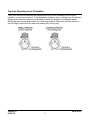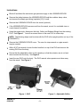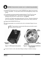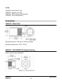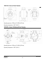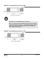
1
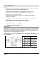
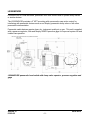
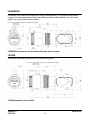
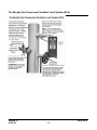
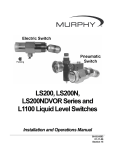
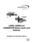
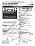
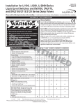
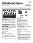
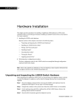
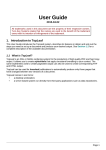
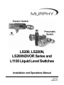
LS200, LS200N,
LS200NDVOR Series and
L1100 Liquid Level Switches
Installation and Operations Manual
00-02-0614
03-05-08
Section 15
In order to consistently bring you the highest quality, full featured products, we reserve the right to change our
specifications and designs at any time. The latest version of this manual can be found at www.fwmurphy.com.
Warranty - A limited warranty on materials and workmanship for one year is given with this FW Murphy product.
A copy of the warranty may be viewed or printed by going to www.fwmurphy.com/support/warranty.htm
CAUTION: LS200 Series parts are not interchangeable with other
Murphy liquid level products. Damage caused by using incorrect
parts is not covered by our Limited Warranty.
Please read the following information before installing. A visual
inspection for damage during shipping is recommended before
mounting.
BEFORE BEGINNING INSTALLATION OF THIS MURPHY
PRODUCT:
•
Disconnect all electrical power to the machine.
•
Make sure the machine cannot operate during installation.
•
Follow all safety warnings of the machine manufacturer.
•
Read and follow all installation instructions.
•
OBSERVE all pressure and electrical ratings and requirements for the devices and the operating environment.
•
BE SURE all pressure HAS BEEN REMOVED from the vessel
before opening any pressure connections.
•
Please contact FW MURPHY immediately if you have any
questions.
Table of Contents
Product Information................................................................................................................ 1
Features .......................................................................................................................1
LS200, L1100...............................................................................................................1
LS200NDVOR..............................................................................................................2
LS200NDVO ................................................................................................................3
LS200N ........................................................................................................................3
Pressure Vessel Installation: LS200, LS200N and L1100.................................................. 4
Direct Installation into the Wall of the Pressure Vessel ................................................4
Installation with a Weld Collar ......................................................................................5
Installation Using Murphy External Float Chamber ......................................................5
Installation and Adjustment for Pneumatic Models.......................................................6
Trip Cam Operating Lever Orientation .........................................................................7
Replacing and Installing the DVO Assembly....................................................................... 8
Models LS200NDVO & LS200NDVOR ........................................................................8
Electrical ................................................................................................................................ 11
Replacement Parts................................................................................................................ 11
Accessories ........................................................................................................................... 12
15050375: Weld Collar..............................................................................................12
55050617: DVU150/DVU175 Adapter Bushing.........................................................12
15051098: External Float Chamber ..........................................................................13
15051168: CB External Float Chamber ....................................................................13
15000478: Float Shaft Extension ..............................................................................14
Specifications........................................................................................................................ 16
All Models...................................................................................................................16
LS200.........................................................................................................................16
LS200NDVOR............................................................................................................16
LS200NDVO ..............................................................................................................16
LS200 N .....................................................................................................................16
L1100 .........................................................................................................................16
Approximate Shipping Weights and Dimensions........................................................16
(THIS PAGE INTENTIONALLY LEFT BLANK)
Product Information
Features
•
Designed for harsh gas compressor scrubber applications
•
304 stainless steel float operates in 0.5 specific gravity and heavier fluids
•
LS200 series rated for 2000 psi (13.8 MPa) [138 bar] working pressure
•
Electric and pneumatic models available
•
Improved design provides better snap action and dependability with reduced
number of moving parts
•
All models screw directly into the vessel or can be mounted via external float
chamber
•
Nickel plated body to provide enhanced corrosion protection
•
Improved float connection thread design provides a more secure connection
•
Listed for Class I, Div. 1, Grp. C & D locations
•
Canadian Registration Number OF1476.2
LS200, L1100
LS200 Liquid Level Switches with 2” NPT mounting are float activated to operate an electrical
SPDT snap switch (optional DPDT on some models) for alarm or shutdown of an engine or
electric motor. The LS200 connects directly into the vessel wall and can be used with a weld
collar (P/N 15050375) or Murphy external float chamber.
L1100 models (1-1/2” NPT) are also available. Refer to the specification table below for L1100
product dimensions.
LS200
A 10.16 in. (258 mm)
LS200, L1100
Section 15
03-05-08
L1100
11 in. (279 mm)
B
3.44 in. (87 mm)
3.50 in. (189 mm)
C
1.75 in. (44 mm)
1.56 in. (40 mm)
D
2.80 in. (71 mm)
3.4 in. (71 mm)
E
2 NPT
1-1/2 NPT
00-02-0614
-1-
LS200NDVOR
LS200NDVOR is a float-activated, pneumatic-vent level device used to operate dump valves
or similar devices.
The LS200NDVOR provides a 2” NPT mounting with a pneumatic snap action output for
interfacing with pneumatic devices such as our Murphy pneumatic dump valve or with other
pneumatic instrumentation.
Pneumatic media devices require clean, dry, instrument quality air or gas. This unit is supplied
with a pressure regulator, filter and Murphy 20BPG pressure gage for improved system life and
trouble-free operation.
LS200NDVOR pneumatic level switch with dump valve operator, pressure regulator and
gage
Section 15
03-05-08
00-02-0614
-2-
LS200NDVO
Pneumatic level switch with snap action Dump Valve Operator (DVO) without the pressure
regulator for those applications where the system provides a filter regulator for “instrument
quality” air or gas as the control medium.
LS200NDVO pneumatic level switch with dump valve operator
LS200N
Pneumatic level switch without the DVO and filter regulator.
LS200N pneumatic level switch
Section 15
03-05-08
00-02-0614
-3-
Pressure Vessel Installation: LS200, LS200N and L1100
Direct Installation into the Wall of the Pressure Vessel
CAUTION: Determine that the float travel is not obstructed by the
coupling in the vessel wall, internal baffles, etc. Do NOT use more than
one float shaft extension P/N 15000478.
Refer to the ‘Pipe Data’ and ‘Minimum Clearance’ tables below.
1.
Make certain the float and extension are tight.
2.
Before installing the level switch, use of a pipe thread sealant is
recommended. Screw the unit directly into the threaded
connection in the wall of the pressure vessel.
3.
For LS200 and L1100, verify that the electrical connection is
positioned at the bottom.
4.
For LS200N the 1/8” NPT pneumatic connection should be on
top (the 3/8” NPT vent connection should be on the bottom) for
service on a “Trip on Rising” application. The LS200N can be
modified for service on a “Trip on Falling” application.
5.
Make the electrical wiring connections according to appropriate
wiring diagrams for the alarm or shutdown system to be used.
The electrical connection is 1/2”-14 NPT.
6.
Ensure all electrical connections are insulated and the cover is
fully installed before reconnecting electrical power.
7.
Verify all pressure connections are tight before pressurizing the system.
Clearance Reference Tables
Nom. Size
(inches)
3
3
4
4
O.D.
(inches)
3.5
3.5
4.5
4.5
Product Name
LS 200
LS 200N
L 1200
L 1200N
L 1100
Section 15
03-05-08
Pipe Data Table
Schedule
Wall Thickness
Number
(inches)
40ST
0.216
80XS
0.3
40ST
0.237
80XS
0.337
Inside Diameter
(inches)
3.068
2.9
4.026
3.826
Minimum Clearance Table
Insertion Depth (inches)
Vertical Clearance (inches)
Std.
w/ 1” Extension
Std.
w/ 1” Extension
4.6
5.6
2.8
3.15
5.43
6.4
3.3
3.9
4.65
5.7
3.9
4.55
5.6
6.7
5.3
6.9
4.4
5.4
3.4
4.05
00-02-0614
-4-
Installation with a Weld Collar
1.
The weld collar, P/N 15050375, must be welded into the wall of
the pressure vessel according to code standards and good
welding practices.
2.
Follow above instructions for installation directly into the wall of
the pressure vessel.
NOTE: Weld collar 15050375 can be used ONLY with
model LS200.
Installation Using Murphy External Float Chamber
1.
Install the Murphy float chamber 15051098 or
15700799 on the outside wall of the pressure vessel
using 1” NPT piping or use the mounting surface
with a bracket. Position the 2” NPT threaded
connection at the height where you want the level
switch to operate. The 2” NPT threaded connection
must be positioned away from the tank wall.
2.
A tee and bleed valve are typically installed at the
bottom of the lower 1 inch pipe riser to allow draining
of the float chamber for servicing or replacement.
NOTE: A typical installation with blocking
and bleed valves is shown at right.
3.
Install the LS200 or LS200N/NDVO/NDVOR in the
2” NPT connection of the float chamber. BE SURE
float travel is not restricted and that the float is tight
onto the float shaft.
4.
To complete installation and wiring, follow the instructions for mounting directly into
wall of the vessel and for wiring.
Section 15
03-05-08
00-02-0614
-5-
Installation and Adjustment for Pneumatic Models
1.
All pneumatic models operate on the vent
principle.
The pneumatic signal source must be clean
and dry “Instrument Quality” air or natural
gas.
The input pneumatic signal must be
regulated between 30 and 70 psi (207-483
kPa) [2 -4.83 bar]. If produced gas is used as
the signal source, it should be taken after gas
passes through the final scrubber. A suitable
filter must be positioned before the
LS200NDVO to prevent liquids and/or
particulates from entering the dump valve
operator.
NOTE: Check filter periodically for wear and tear and elements that
hamper the flow of the pneumatic signal.
2.
All pressure connections must be tight and maintained tight so as not to leak air/gas.
3.
Valve seat adjustment can be made if air/gas begins to leak. Care should be taken
when adjusting as only slight movement is necessary to stop the leakage; excessive
force will bind the seating mechanism. See the instruction below for adjustment.
CAUTION: Avoid excessive Teflon tape which may inhibit proper
operation.
Section 15
03-05-08
00-02-0614
-6-
Trip Cam Operating Lever Orientation
The LS200 series level switches are shipped with the trip cam orientation set for normal
operation, or vent on rising level. If the application requires a vent on falling level, the trip cam
operating lever can be moved to the alternate position as indicated in the diagram below.
Gently depress the cam and rotate to the other lever position. Make sure the cam returns to
the full height position with the cam lever resting fully in the grove.
Section 15
03-05-08
00-02-0614
-7-
Replacing and Installing the DVO Assembly
NOTE: When replacing/installing the DVO assembly, tubing and fitting
modifications may be required. We suggest removing the
LS200NDVO/DVOR from the vessel. Relieve pressure from the vessel or
use block valves before removing the LS200NDVO/DVOR.
Models LS200NDVO & LS200NDVOR
NOTE: Clean, dry instrument-quality gas should be used. Use and
regular maintenance of filters will improve service life and reliability.
Tools Needed
•
Strap or pipe wrench
•
9/16” Hex wrench
•
Tubing cutters and benders
CAUTION: LS200 series parts are not interchangeable with the L1200
Series.
Section 15
03-05-08
00-02-0614
-8-
Instructions
1.
Block off and bleed the instrument gas pressure supply to the LS200NDVO/DVOR.
2.
Remove the tubing between the LS200NDVO/DVOR and the scrubber dump valve,
and remove the supply gas tubing (regulator [-R-] if used).
3.
Remove the LS200NDVO/DVOR from the vessel (optional).
4.
If the LS200NDVO/DVOR was removed from the vessel, mount it in a suitable vise on
a work bench (if possible).
5.
Using the proper tools, disconnect the Inlet, Outlet, and Exhaust fittings from the existing
DVO. See Figure 1. You will re-connect these to the new DVO in a later step.
NOTE: The following steps must be done with the DVO in the upright position (on top of the
LS200NDVO).
6.
Remove the LS200NDVO/DVOR cover. The use of a strap wrench or a pipe wrench
may be needed.
7.
With a 9/16” hex wrench, loosen the hex head bolt on top of the DVO and remove the
existing DVO from the body.
8.
Ensure that the adjustable orifice is fully raised up so that the actuator arm is not bent
when inserted into the body. See Figure 2.
9.
Insert the new DVO onto the body. The DVO manual valve operator must face away
from the vessel. See Figure 3.
Figure 1 - DVO
Section 15
03-05-08
Figure 2 – Adjustable Orifice
00-02-0614
-9-
CAUTION: Ensure that the actuator arm is not bent during reassembly.
10.
With the DVO aligned over the hex on the LS200NDVO body, tighten the valve using
the 9/16” hex wrench. You may need to hold the DVO while tightening to keep it from
rotating.
11.
The pneumatic input signal should be regulated between 30 and 70 psi for proper
setting of the adjustable orifice. With the float in the down position adjust the
adjustable orifice down until it touches the seat. See Figure 4.
If the DVO is still leaking make slight adjustments (1/32 turn). Excessive adjustments
will lock up mechanisms. After adjusting make sure float moves freely up and down.
12.
Replace the LS200NDVO/DVOR cover.
13.
Using the appropriate tools re-install the inlet, outlet, and exhaust fittings to the new
DVO.
NOTE: Thread sealant is recommended although care should be used to
not allow excess to enter valve.
Figure 3 – DVO manual valve operator
14.
Figure 4 – Orifice Adjustment with float in
down position
Connect to the inlet, outlet, and exhaust fittings according to installation drawings.
Section 15
03-05-08
00-02-0614
- 10 -
Electrical
Replacement Parts
CAUTION: LS200 Series parts are not interchangeable with other
Murphy liquid level products. Damage caused by the above
mentioned is not covered by our Limited Warranty.
Order by part number designation.
LS200
15000479:
15000124:
15010268:
15000478:
Stainless Steel float for LS200 (not interchangeable with L1200)
SPDT snap switch assembly
LS200 counter balance assembly
Float shaft extension (not interchangeable with L1200)
LS200N
15000479: Stainless steel float for LS200N (not interchangeable with L1200)
15051133: Valve stem
LS200NDVO and LS200NDVOR
55050621: Regulator only
05706499: 20BPG-D-75 Pressure MURPHYGAGE®
0-75 psi (517 kPa) [5.17 bar]
15010267: Assembly (LS200N DVO Assembly)
Section 15
03-05-08
00-02-0614
- 11 -
L1100
15000893:
15000937:
15000124:
15000892:
BUOYGLAS™ float
Stainless steel float
SPDT snaps switch assembly
Float shaft extension
Accessories
15050375: Weld Collar
Operating Pressure: 2000 psi (13.8 MPa) [138 bar].
Operating Temperature: 400°F (204°C).
55050617: DVU150/DVU175 Adapter Bushing
Order by part number designation
Section 15
03-05-08
00-02-0614
- 12 -
15051098: External Float Chamber
Operating pressure: 2000 psi (13.8 MPa) [138 bar]
Operating temperature: 400°F (204°C).
15700799: Series 100 External Float Chamber
Operating pressure: 2000 psi (13.8 MPa) [138 bar]
Operating temperature: 400°F (204°C).
Section 15
03-05-08
00-02-0614
- 13 -
15000478: Float Shaft Extension for the LS200
CAUTION: Not interchangeable with L1200 parts.
Use of 1” extension requires additional clearance and will operate
in .65 specific gravity and heaver. See ‘Minimum Clearance Table’
listed in the “Pressure Vessel Installation: LS200, LS200N and
L100” chapter of this manual.
15000892: Float Shaft Extension for the L1100
Section 15
03-05-08
00-02-0614
- 14 -
The Murphy Gas Compressor Scrubber Level System (SLS)
Section 15
03-05-08
00-02-0614
- 15 -
Specifications
All Models
• Body: Nickel plated steel; optional 316 stainless steel (meets NACE standard MR-01-75 for direct exposure to H2S service)
• Float: 304 stainless steel to operate in 0.5 specific gravity or heavier fluids
• Pressure rating: 2000 psig (13.8 MPa) [138 bar] (LS200 models only)
• O-ring: Viton
LS200
• Process connection: 2” NPT
• Temperature rating: -20 to 300°F (-29 to 149°C)
• Electrical: SPDT std. (see “Electrical” section for configuration/rating.
• Wiring: 18 AWG x 36 in. (1.0 mm x 916 mm)
2
LS200NDVOR
• Process connection: 2” NPT
• DVO valve: 3 way N.C. w/manual operator, all connections 1/8” NPT (minimum 30 psig required)
• Filter/pressure regulator set:
• Regulator: 0 to 75 psig (0 to 517 kPa) [0 to 5.17 bar] range
• Maximum input pressure: 300 psig (2.07 MPa) [20.7 bar]
LS200NDVO
• Process connection: 2” NPT
• DVO valve: 3 way N.C. w/manual operator; all connections 1/8” NPT
LS200 N
• Process connection: 2” NPT
• Vent valve: 2 way N.C. snap action w/ 1/16in. (2mm) orifice and Viton seat; Inlet: 1/8” NPT; outlet 3/8” NPT
L1100
• Process connection: 1-1/2” NPT
• Pressure rating: 1500 psig (10.3 MPa) [103.2 bar]
• Float: BUOYGLAS™ operates to 0.5 specific gravity;
Optional stainless steel to operate in 0.65 specific gravity
• Electrical: SPDT switch
Approximate Shipping Weights and Dimensions
All models: 6 lb. 10 oz. (3 kg);
14 x 5 x 3-1/2 in. (356 x 127 x 89 mm)
Section 15
03-05-08
00-02-0614
- 16 -
MURPHY, the Murphy logo, and Liquid level Switches (LS) are registered and/or common law trademarks of
Murphy Industries, Inc. This document, including textual matter and illustrations, is copyright protected by Murphy
Industries, Inc., with all rights reserved. (c) 2005 Murphy Industries, Inc. Other third party product or trade names
referenced herein are the property of their respective owners and are used for identification purposes only.
Section 15
03-05-08
00-02-0614
- 17 -