1
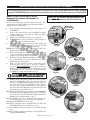
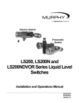
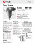
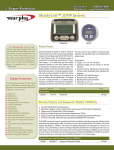
00-02-0175
Revised 03-06
Section 15
Installation for L1100, L1200, L1200N Series
Liquid Level Switches and DVU150, DVU175,
and DVU2105/2115/2120 Series Dump Valves.
Please read the following instructions before installing. A visual inspection for damage during shipping is recommended before mounting.
GENERAL INFORMATION
**
Description
Series L1100 and L1200 Liquid Level Switches are float activated to
operate an electrical SPDT snap switch (optional DPDT on some models) for alarm
or shutdown of an engine or electric motor. They screw directly into the wall of the
vessel. Series L1200 can also be used with a weld collar or external float chamber.
WARNING
BEFORE BEGINNING INSTALLATION OF THIS MURPHY PRODUCT
✔
✔
✔
✔
✔
Disconnect all electrical power to the machine.
Make sure the machine cannot operate during installation.
Follow all safety warnings of the machine manufacturer.
Read and follow all installation instructions.
OBSERVE all pressure and electrical ratings and requirements for the devices and the operating environment.
✔ BE SURE all pressure HAS BEEN REMOVED from the
vessel before opening any pressure connections.
Series L1200N is a float-activated, pneumatic-vent level device used to operate dump
valves or similar devices. This model screws directly into the vessel or can be
mounted via an external float chamber. It cannot be used with weld collar 15050375.
Model variations include a dump valve operator with or without a filter/pressure
regulator and indicating pressure gauge.
NOTE: All stainless steel versions of L1100, L1200, L1200N, L1200NDVO, and
L1200NDVOR series carry Canadian Registration Number OF1476.2.
DIS
CO
NT
INU
ED
Specifications
L1100
Series DVU150, DVU175, DVU2105/2115/2120 Dump Valves receive a
pneumatic input signal to cause an orifice to open or close allowing liquid
condensate to be drained from a pressure vessel. A pop up button indicates valve
open/closed. Stainless steel versions available.
L1111
L1200
L1200N
L1200NDVO
L1200NDVOR
Body
• Standard: Electroless Nickel plated steel
• Optional: 316 Stainless Steel†
✗A
✗A
✗A
✗A
✗B
✗B
✗B
✗B
✗B
✗B
✗B
✗B
Pressure Rating
• 15 psi (103 kPa) [1.03 bar] Polyethylene Float
• 1500 psi (10.3 MPa) [103.42 bar] Stainless Float
• 2000 psi (13.8 MPa) [138 bar] BUOYGLAS™ Float
✗
✗
✗
✗
✗
✗
✗
✗
✗
✗
✗
✗
Temperature Rating
• Standard: -20/175°F (-29/79°C)
• Standard: -20/300°F (-29/149°C)
• Optional: -20/400°F (-29/204°C)*
✗
✗
✗
✗
✗
✗
✗
✗
✗
✗
✗
✗
✗
✗
✗
✗
✗
✗
✗
✗
✗
✗
Electrical
• Standard SPDT: 5 A @ 125/480 VAC (see p. 3 for full ratings)
• Optional DPDT: 10 A @ 250 VAC (see p. 3 for full ratings)
✗
✗
✗
✗
✗
✗
Wire: 18 AWG x 36 in. (1.0 mm2 x 914 mm)
✗
✗
✗
✗
✗
✗
✗
✗
✗
✗
✗
✗
✗
✗
Specific Gravity
• Standard: 0.5 with BUOYGLAS™ float
• Optional: 0.65 with 304 Stainless Steel†
• Standard 0.73 Polyethylene Float
O-Rings: Viton
Valve: Two-way snap-action vent type
• 1/8 in. (3 mm) orifice w/Viton “A” seat
• 1/8 NPT inlet; 1/4 NPT vent
• 30-70 psi (207-483 kPa) [2.07-4.83 bar] operating pressure
Dump Valve Operator: Operates Murphy DV Series
dump valves or similar. 1/8 NPT inlet, outlet & vent.
Pressure Regulator/Filter and Murphy 20BPG:
0-75 psi (0-517 kPa) [0-5.17 bar] pressure gauge.
Maximum input 300 psi (2.07 MPa) [20.68 bar].
1/8 NPT in/out.
Operation:
H=For high level, L=For low level
✗
H
L
H
H
H
†Meets NACE standard MR-01-75 for direct exposure to H S service.
*Not available with DPDT snap-switch.
A =1-1/2 NPT
B =2 NPT
2
**Products covered by this literature comply with EMC Council directive 89/336/EEC regarding electromagnetic compatibility.
Installation 00-02-0175 page 1 of 6
H
DIMENSIONS
L1200N, L1200NDVO and L1200NDVOR with
Dump Valve Operator, Pressure
Regulator and Gage
L1100 and L1200
11 in.
(279 mm)
Pressure
Regulator
with 20BPG
Pressure Gage
3-1/2 in.
(89 mm)
2-3/16 in.
(56 mm)
New Dump Valve
Operator Assembly
p/n 15010216
See
Note 2
1/2 NPT
See
Note 1
3-5/8 in.
(92 mm)
Note 1:
L1100: 1-1/2 NPT
L1200: 2 NPT
Note 2: 1-9/16 (40 mm)
SF option:
L1100: 1-1/2 (38 mm)
L1200: 1-3/4 (44 mm)
1/8 NPT
Old Round Dump Valve
Operator Assembly
p/n 15000940
Float travel between Operate
and Reset= 0.25 in. (6 mm).
Switch operates on Rising Level
w/ float at horizontal centerline
±0.25 in. (6 mm).
1/8 NPT
INLET
3-5/8 in. (92 mm)
5 in. (127 mm.) minimum
clearance is required for
float movement.
3/4 Hex
(See Note)
DIS
CO
NT
INU
ED
2-3/16 in.
(56 mm)
1/4 NPT
VENT
1-9/16 in.
(40 mm)
SF option=
1-3/4 in.
(44 mm)
2" 11-1/2 NPT
3-1/2 in. (89 mm)
SF= 3-3/4 in. (95 mm)
11 in. (279 mm) SF option= 11-1/4 in. (286 mm)
Note: For use only with Old Round Dump Valve Operator Assembly (15000940).
L1111
11-5/16 in.
(287 mm)
3-53/64 in.
(97 mm)
2-3/16 in.
(56 mm)
DVU150, DVU175, DVU2105/2115/2120
Series Dump Valves
A
See
Note
1/2 NPT
1-1/2 NPT
3-5/8 in.
(92 mm)
Note: 1-9/16 (40 mm)
Pressure
Inlet Port
1/8 in.-27 NPT
Float travel between Operate
and Reset= 0.25 in. (6 mm).
Switch operates on Rising Level
w/ float at horizontal centerline
±0.25 in. (6 mm).
Manual Valve
Operator
B
Vent
Weep Hole
Union
Valve Open/Closed
Indicator Button
F Drain
Connection
C
Electrical installation to be done by
qualified person according to the NEC.
D
E
(dimension shown
G for
reference only)
Plug Seal
Model
A
B
C
D
E
F
G
DVU2120
DVU2115
DVU2105
DVU175
DVU150
7.50 (191)
7.50 (191)
7.50 (191)
7.50 (191)
7.50 (191)
8.0 (203)
8.0 (203)
8.0 (203)
6.75 (171)
6.75 (171)
2.75 (70)
2.75 (70)
2.75 (70)
2.06 (52)
2.06 (52)
1.0 (25)
1.0 (25)
1.0 (25)
1.0 (25)
1.0 (25)
2-11.5 NPT
2-11.5 NPT
2-11.5 NPT
1-11.5 NPT
1-11.5 NPT
1-11.5 NPT
1-11.5 NPT
1-11.5 NPT
3/4”-14 NPT
1/2”-14 NPT
1.03
1.03
1.03
1.03
1.03
NOTE: Dimensions are in inches and (millimeters)
Installation 00-02-0175 page 2 of 6
REPLACING AND INSTALLING THE DVOA ASSEMBLY
When replacing/installing the old style DVO assembly with the new style (DVOA), tubing and fitting modifications are required. We suggest
removing the L1200NDVO/DVOR from the vessel. Relieve pressure from the vessel or use block valves before removing the L1200NDVO/DVOR.
Replacing and Installing the DVOA
Assembly For Models L1200NDVO &
L1200NDVOR
NOTE: Clean, dry instrument quality gas should be used.
Use of filters will improve service life and reliability.
Tools Needed: Strap or pipe wrench; 3/4” Hex wrench; 9/16” hex
wrench; needle nose pliers; tubing cutters and benders and the
appropriate tools for the fittings.
1.
Block off and bleed the instrument gas pressure supply to the
L1200NDVO.
2.
Remove the tubing between the L1200NDVO and the
separator dump valve, and remove the supply gas tubing
(regulator [-R] if used).
3.
Remove the L1200NDVO from the vessel (optional).
4.
If the L1200N was removed from the vessel, mount it in a
suitable vise on a work bench (if possible).
5.
Using the proper tools, disconnect the Inlet, Outlet and
Exhaust fittings from the existing DVO (see fig. 1). You will
re-connect these to the new DVOA in a later step.
NOTE: The following steps must be done with the DVO in the
upright position (on top of the L1200N).
6.
Remove the L1200N cover (this will aid with the alignment
of the new DVOA Valve Bushing). The use of a strap
wrench or a pipe wrench may be needed.
7.
Insert the new Valve Bushing through the new DVOA (see
fig. 2). The markings on top of the DVOA must be facing
up. This will be needed in step 9.
8.
With a 3/4” hex wrench loosen the existing DVO, valve
stem, and static seal (see fig. 3). Once the assembly is
loosened, VERY CAREFULLY use needle nose pliers to
hold the Valve Seat Assembly in place. Remove the existing
DVO making sure the Valve Seat Assembly inside the
L1200NDVO is aligned and straight (see fig. 4).
Old DVO
Outlet
(opposite side)
Inlet
DIS
CO
NT
INU
ED
Exhaust
Figure 1
Figure 2
New DVOA
Figure 3
CAUTION: MAKE SURE the Valve Seat Assembly inside
the L1200N remains in place after removing the DVO.
Holding the Seat Assembly up with the needle nose pliers
inside the L1200NDVO body, place the tip of the new
DVOA valve bushing through the spring and into the hole in
the center of the valve seat, and tighten the valve bushing.
The Valve Seat Assembly should be able to move freely up
and down after the bushing has been tighten. The DVO red
button must face away from the vessel.
10.With the new DVOA aligned over the hex on the L1200NDVO
body, tighten the Valve Bushing using the 9/16” hex wrench.
You may need to hold the DVOA while tightening the Valve
Bushing to keep it from rotating (see fig. 5).
11.If the L1200N is in the vise, operate the float and inspect for
smooth and proper operation of the Valve Seat Assembly.
12.Replace the L1200NDVO cover (see fig. 6).
13.Using the appropriate tools re-install the Inlet, the Outlet and
the Exhaust fittings to the new DVOA (see fig. 5).
14 If the L1200N was removed from the vessel re-install it at this
time.
15.Modify existing or install new tubing to connect the Inlet, the
Outlet and Exhaust fittings.
Valve
Bushing
Valve Seat
Assembly
9.
Outlet
Figure 4
Inlet
Installation 00-02-0175 page 3 of 6
Exhaust
New DVOA
Figure 5
L1200N
Cover
Figure 6
PRESSURE VESSEL INSTALLATION: L1100, L1200, and L1200N
Direct Installation into the Wall of the
Pressure Vessel
1. Determine that the float travel is not
obstructed by the coupling in
Tank
the vessel wall, internal
Wall
baffles, etc.
Do NOT use more than
one arm extension P/N
15050395.
Explosion proof
2. BE SURE that the float
Level
conduit seal
Switch
and extension are tight
where required.
and that the lock washer is
in place.
3. Before installing the level
switch a suitable pipe thread sealant
is recommended. Screw the unit directly into the threaded
connection in the wall of the pressure vessel.
4. Be sure that the electrical connection is positioned at the
bottom. For L1200N the 1/8 NPT pneumatic connection
should be on top (the 1/4 NPT vent connection should be on
the bottom). See “Pneumatic models” section for further
instructions for the L1200N.
5. Make the electrical wiring connections according to
appropriate wiring diagrams for the alarm or shutdown
system to be used. The electrical connection is 1/2-14 NPT.
Electrical wiring and conduit should be installed by qualified
personnel according to the NEC.
6. BE SURE all electrical connections are insulated and the
cover is fully installed before reconnecting electrical power.
7. BE SURE all pressure connections are tight before
pressurizing the system.
positioned away from the tank wall.
2. A tee is typically installed at the bottom of the lower 1 inch
pipe riser to allow draining of the float
chamber for servicing or replacement.
NOTE: A typical installation
Float
with Blocking and Bleed valves is Chamber
Tank
shown at right.
Block
Valves
3. Install the L1200 or
L1200N
Level
in the 2 NPT connection Switch
of
Tee
the float chamber.
Bleed
BE SURE float travel
Valve
is not restricted and that the
Explosion proof
float is tight onto
conduit seal
where required.
the float shaft.
4. To complete installation and
wiring, follow the instructions for
mounting directly into wall of the vessel and for wiring.
DIS
CO
NT
INU
ED
Installation with a Weld
Collar
Tank Wall
1. The weld collar, P/N
Weld Collar
15050375, must be welded
into the wall of the
pressure vessel according
to code standards and
good welding practices.
L1200
2. Follow above instructions
for installation directly into
Explosion proof
the wall of the pressure
conduit seal
vessel.
where required.
3. NOTE: Weld collar 15050375 can
be used ONLY with model L1200. It cannot be used with
L1200N.
Installation Using External
Float Chamber 15051098
Pneumatic Models
1. All pneumatic models
operate on the vent
Filter/Regulator
Tank
principle. The
New Dump Valve
Operator Assembly
pneumatic signal
Pneumatic
p/n 15010216
Signal
source MUST BE
CLEAN AND DRY.
The input pneumatic MURPHYGAGE®
signal must be
regulated between 30
L1200N
and 70 psi (207-483
kPa) [2.07-4.83 bar].
If produced gas is used as the
signal source, it should be taken
after gas passes through the final scrubber.
A suitable filter must be positioned before the L1200NDVO
to prevent liquids and/or particulates from entering the dump
valve operator.
NOTE: Check filter periodically for wear and tear and
elements that hamper the flow of the pneumatic signal.
2. All pressure connections must be tight and maintained tight
so as not to leak air/gas.
3. Valve seat adjustment can be made if air/gas begins to leak.
Care should be taken when adjusting as only slight movement
is necessary to stop the leakage; excessive force will bind the
Hex Socket Set Screw
• loosen for adjustment
• tighten after adjustment
L1200N
CAUTION: USE “NON SPARKING TOOLING”.
1. Install the float chamber 15051098 on the outside wall of the
pressure vessel using 1 NPT piping. Position the 2 NPT
threaded connection at the height where you want the level
switch to operate. The 2 NPT threaded connection must be
Hex Adjustment Nut
• turn left until air
seepage stops
• Caution: only slight
adjustment is needed—too
much will lock up mechanism
Installation 00-02-0175 page 4 of 6
Trip Cam (float down)
• should be in
this position
• non-adjustable
TYPICAL INSTALLATION ON GAS COMPRESSORS
Basic Operation
As condensate rises in the scrubber, the float on
the L1200NDVOR rises and trips its pneumatic
valve. The valve opens allowing pressure to enter
the dump valve pilot chamber. Once the pressure
enters the pilot chamber it forces the diaphragm
and valve stem forward thus opening the valve seat
(valve open/closed indicator button pops out) and
releasing condensate through the valve stem and
out the drain. As the condensate level drops, the
L1200NDVOR pneumatic valve closes to shut off
the pressure to the dump valve causing it to close.
If for any reason the condensate continues to rise
beyond normal dump levels, model L1200
operates the alarm and/or shuts down
the equipment.
The L1200NDVOR Filter/Regulator and the
MURPHYGAGE® help keep the control pressure
clean and dry. They also allow the operator to
adjust pressure to recommended levels.
Typical/Scrubber/Separators
VESSEL
Minimum control
pressure 30 psi
(207 kPa) [2.07 bar]
Rising Level Shutdown
L1200 (with snap-switch)
Explosion proof
conduit seal required
for Class I. Div 1, not
required for intrinsically
safe or non-incendive
circuits like FWM TTD.
Rising
Level
Trips
DVO
Electrical
Conduit
L1200NDVOR
Dump Valve
Operator
Union
Air Supply Maximum
300 psi (2.07 MPa)
[20.70 bar]
Filter/Regulator
with MURPHYGAGE®
Minimum control pressure
30 psi (207 kPa) [2.07 bar]
DIS
CO
NT
INU
ED
DVU Series Dump Valve
Union
Condensate Line (Out)
Manual Drain Valve
REPLACEMENT PARTS
ELECTRICAL INFORMATION
DPDT (Snap Switch)
SPDT (Snap Switch)
Green Grd. Connection
Black N.O.
White COM.
Red N.C.
Switch Rating: 5 A @ 125-250- 480 VAC
1/2 A @ 125 VDC
1/4 A @ 250 VDC
2A @ 6-30 VDC Resistive
1A @ 6-30 VDC Inductive
Green Grd. Connection
Black N.O.
White COM.
Red N.C.
Blue N.C.
Yellow COM.
Orange N.C.
Switch Rating: 10 A @ 125-250 VAC
1/2 A @ 125 VDC
1/4 A @ 250 VDC
10 A @ 6-24 VDC
Inductive/Resistive
Order by part number designation.
L1100/L1200*
15000893: BUOYGLAS™ float
15000894: Stainless Steel float for L1200
15000937: Stainless Steel float for L1100
15000124: SPDT snap switch assembly
15010213: L1100 counter balance assembly
15010214: L1200 counter balance assembly
L1200N
15050420: Cam spring return
15050421: Cam
15000893: BUOYGLAS™ float
15000894: Stainless Steel float for L1200N
15050453: Valve stem
15010189: Counter balance assembly
L1200NDVO and L1200NDVOR
55050621: Regulator only
05706499: 20BPG-D-75 Pressure MURPHYGAGE®
0-75 psi (517 kPa) [5.17 bar]
15010216: DVOA assembly (New rectangular style)
15000940: DVO assembly (Old round style)
*To maintain hazardous location listings, all other repairs must be made by the factory.
Installation 00-02-0175 page 5 of 6
ACCESSORIES
Order by part number designation.
55050617: DVU150/DVU175 Adapter Bushing
15050375: Weld Collar
Material: 2-1/2 Hex bar stock C.R.S
2-1/16 in
(52 mm)
1-1/16 in
(27 mm)
2 NPT
2-1/2 in
(64 mm)
2-7/8 in
(73 mm)
3-5/8 in.
(92 mm)
1 NPT
4-1/2 in
(114 mm)
Operating Pressure: 2000 psi (13.8 MPa) [138 bar].
Operating Temperature: 400°F (204°C).
2 NPT
15051098: External Float Chamber
3 in.
(76 mm)
1-11.5 NPT (2 places)
DIS
CO
NT
INU
ED
2-11.5 NPT
10.5 in.
(266 mm)
3 in.
(76 mm)
1/2-20 UNF-2B
(4 places)
7.55 in.
(192 mm)
3.5 in.
(89 mm)
Material: Cast Steel, WCB
7.01 in.
(179 mm)
Operating Pressure: 2000 psi (13.8 MPa) [138 bar].
Operating Temperature: 400°F (204°C).
15000892: Float Shaft Extension
10-32 UNF
10-32 UNF
3/8 in
(10 mm)
1-3/8 in
(35 mm)
Warranty
A limited warranty on materials and workmanship is given with this FW Murphy product.
A copy of the warranty may be viewed or printed by going to www.fwmurphy.com/support/warranty.htm
www.fwmurphy.com
918.317.4100 Email: [email protected]
MURPHY, the Murphy logo are registered and/or common law trademarks of Murphy Industries, Inc. This document,
including textual matter and illustrations, is copyright protected by Murphy Industries, Inc., with all rights reserved.
(c) 2006 Murphy Industries, Inc. Other third party product or trade names referenced herein are the property of
their respective owners and are used for identification purposes only.
Installation 00-02-0175 page 6 of 6