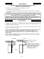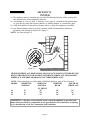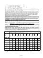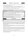
1
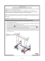
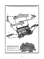
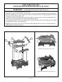
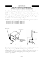
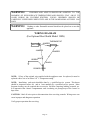
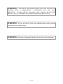
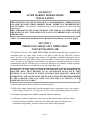
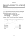
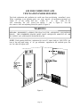
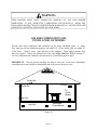
MODEL CR/DX MANUAL VENT-FREE OR VENTED GAS LOGS CR/DX 18”, 24”, 30” & CR 24” MOUNTAINEER , CR24 ASPEN LOG SETS FOR NATURAL OR LIQUID PETROLEUM (L.P.) WITH OPTIONAL HEAT SHIELD MODEL (19HS) WARNING: If the following information in this manual is not followed exactly, a fire or explosion may result causing property damage, personal injury, or loss of life. -DO NOT STORE OR USE GASOLINE OR OTHER FLAMMABLE VAPORS AND LIQUIDS IN THE VICINITY OF THIS OR ANY OTHER APPLIANCE. -WHAT TO DO IF YOU SMELL GAS * Do not try to light any appliance. * Do not touch any electrical switch; do not use any phone in your building. * Immediately call your gas supplier from a neighbor's phone. Follow the gas supplier's instructions. * If you cannot reach the gas supplier, call the fire department. -Installation and service must be performed by a qualified installer, service agency, or the gas supplier. -This appliance is intended for supplemental heating. This is an unvented and vented gas-fired heater. It uses air (oxygen) from the room in which it is installed. Provisions for adequate Combustion and Ventilation Air must be provided. Refer to Section V, page 34. This appliance may be installed in an aftermarket, permanently located, manufactured (mobile) home, where not prohibited by local codes. This appliance is only for use with the type of gas indicated on the rating plate. This appliance is not convertible for use with other gases. WARNING: This appliance is equipped for (natural or propane) gas. Field conversion is not permitted. INSTALLER: Leave this manual with the appliance. CONSUMER: Retain this manual for future reference. New Buck Corporation P.O. Box 69 200 Ethan Allen Drive Spruce Pine, NC 28777 www.buckstove.com Revised January 2013 TABLE OF CONTENTS SECTION I: Safety Information ..................................................................................................3 SECTION II: Residential Installation-Unvented Gas Logs .......................................................6 Clearances .....................................................................................................................................7 Gas Connection .............................................................................................................................8 Preparing Log Kit..........................................................................................................................8 Log Placement Diagrams ........................................................................................................ 9-16 Gas Pressure Check.....................................................................................................................17 Lighting Instructions-Millivolt Valve (SIT) ...............................................................................18 Lighting Instructions-Modulating Valve (SIT) ...........................................................................22 Lighting Instructions-Manual Valve (SIT) .................................................................................26 Flame Check................................................................................................................................30 Heat Output .................................................................................................................................30 SECTION III: Installation-Heat Shield.......................................................................................31 Wiring Diagram...........................................................................................................................33 SECTION IV: Installation-After Market Mobile Home .............................................................35 SECTION V: Producing Adequate Combustion and Ventilation Air.........................................35 Air For Combustion And Ventilation Inside Building................................................................38 Air For Combustion And Ventilation Outdoors..........................................................................39 SECTION VI: Vented Logs ........................................................................................................40 Important Safeguards ..................................................................................................................42 Cleaning ......................................................................................................................................42 Troubleshooting ..........................................................................................................................43 Servicing and Replacement Parts................................................................................................48 Warranty......................................................................................................................................52 Owner Registration Card..............................................................................................Back Cover SECTION I SAFETY INFORMATION WARNINGS IMPORTANT: READ THIS OWNER'S MANUAL CAREFULLY AND COMPLETELY BEFORE TRYING TO ASSEMBLE, OPERATE, OR SERVICE THE APPLIANCE. IMPROPER USE OF THESE LOGS CAN CAUSE SERIOUS INJURY OR DEATH FROM BURNS, FIRE, EXPLOSION, AND CARBON MONOXIDE POISONING. Early signs of carbon monoxide poisoning resemble the flu, with headaches, dizziness, and/or nausea. If you have these signs, the heater may not be working properly. Get fresh air at once! Turn off gas. Have burner serviced. Some people (such as pregnant women, persons with heart or lung disease, persons with anemia, those under the influence of alcohol, and those at high altitudes) are more affected by carbon monoxide than others. Make certain you understand and read all Warnings. Keep this manual for reference. It is your guide to safe and proper operation of these logs. 1. Install log set only in a solid-fuel-burning masonry fireplace or U.L. listed prefabricated fireplace constructed of non-combustible materials. 2. The installation must conform with local codes or, in the absence of local codes, with the National Fuel Gas Code, ANSI Z223.1/NFPA 54. 3. This appliance may be installed in an After Market* Manufactured (Mobile) Home, where not prohibited by state or local codes. (* After Market: Completion of sale, not for purpose of resale from the manufacturer.) NOTE: This appliance is only for use with the type of gas indicated on the rating plate. This appliance is not convertible for use with other gases. NOTE: See Section IV for Mobile Home Installation and Producing adequate Combustion and Ventilation Air. IMPORTANT: VENT-FREE HEATERS ADD MOISTURE TO THE AIR. ALTHOUGH THIS IS BENEFICIAL, INSTALLING HEATER IN ROOMS WITHOUT ADEQUATE VENTILATION MAY CAUSE MILDEW TO FORM FROM TOO MUCH MOISTURE. 4. Never install the log set: -in a recreational vehicle. -where curtains, furniture, clothing, or other flammable objects are less than 42" from the front of the heater. -in high traffic areas or in windy areas. NOTE: These log sets comply with both the ANSI Z21.11.2b-2010 "Unvented Room Heater" and ANSI Z21.60b-2004. CSA 2.26-2004 Decorative Appliance For "Solid Fuel Burning Fireplace". “WARNING: ANY CHANGE TO THIS HEATER OR ITS CONTROLS CAN BE DANGEROUS.” Page 3 5. Two models are available. One specific model for propane (LP) and one for natural gas. Use the correct gas type for your home. This unit is not field convertible. 6. If these gas logs are for use with propane gas, do not place propane supply tank(s) inside any structure. Locate propane supply tank(s) outdoors. 7. If you smell gas: -Shut off gas supply. -Do not try to light any appliance. -Do not touch any electrical switch; do not use any phone in your building. -Immediately call your gas supplier from a neighbor's phone. Follow the gas supplier's instructions. -If you cannot reach your gas supplier, call the fire department. 8. When operated for the first time, the logs may emit a "paper burning" smell. This smell will gradually diminish and will be totally eliminated after the first few hours of operation. Run the gas logs with the flue damper open during this time. Do not use the blower at this time. 9. "This heater shall not be installed in unusually tight construction unless provisions are provided for adequate combustion and ventilation air. "See Section V - “Producing Adequate Combustion and Ventilation Air”, page 34. 10. Surface of gas logs becomes very hot when operating. Keep children and adults away from hot surface. Gas logs will remain hot for some time after shutdown. Allow surface to cool before touching. 11. Never place any objects on these gas logs. 12. These gas logs MUST NOT BE USED with glass doors in the closed position. 13. If equipped, fresh air damper must be closed. 14. Keep appliance area clean and free from combustible materials, gasoline, and other flammable vapors and liquids. Keep burner and control compartment clean. See installation and operating instructions accompanying heater. 15. If burner shuts off, do not relight until you provide fresh outside air. If burner keeps shutting off, have unit serviced. 16. An unvented room heater having input rating of more than 10,000 BTU per hour shall not be installed in a bedroom or bathroom. 17. Maintain clearance around air openings. WARNING: This appliance is equipped for (natural or propane) gas. Field conversion is not permitted. Page 4 18. Do not use the appliance if any part has been under water. Immediately call a qualified service technician to inspect the appliance and to replace any part of the control system and any gas control which has been under water. 19. Turn off the gas logs and let cool before servicing. 20. The logs are made of light weight refractory. Hold both ends of the logs when removing or replacing. 21. Make sure any safety screen or guard (if any) that was removed for servicing is in place before operating gas logs. 22. Strong drafts, such as a ceiling fan placed directly in front of the fireplace, may create sooting. Sooting may discolor walls. 23. Installation and repair should be done by a qualified service person. The heater and the gas logs should be inspected before use and at least annually by a professional service person. More frequent cleaning may be required due to excessive lint from carpeting, bedding materials, etc. It is important that the control compartment, burners, and circulating air passageways of these gas logs be kept clean and clear. 24. Do not use these gas logs for burning trash or cooking. Never place matches, paper, garbage or any other material on top of logs or into the flames. 25. Do not install or operate these gas logs in areas where impurities in the air exist (such as tobacco smoke and heavy cooking grease). Particles from impurities may discolor walls. 26. The appliance and its individual shutoff valve must be disconnected from the gas supply piping system during any pressure testing of that system at test pressures in excess of 1/2 psi (3.5 kPa). 27. The appliance must be isolated from the gas piping system by closing its individual manual shut off valve during any pressure testing of the gas supply piping system at test pressures equal to or less than 1/2 PSIG. 28. Any outside air ducts and/or ash dumps in the fireplace shall be permanently closed at time of appliance installation. 29. Due to high temperatures, the appliance should be located out of traffic and away from furniture and draperies. 31. Do not place clothing or other flammable material on or near the appliance. WARNING: “State or local codes may only allow operation of this appliance in a vented configuration. Check your state on local codes”. Page 5 SECTION II RESIDENTIAL INSTALLATION OF GAS LOGS FIREPLACE PREPARATION The fireplace needs to be prepared before installing the gas logs. A. Turn off the gas supply to the fireplace. B. Any outside air ducts on the fireplace shall be permanently closed at the time of the appliance installation. “WARNING: BEFORE INSTALLING IN A SOLID FUEL BURNING FIREPLACE, THE CHIMNEY FLUE AND FIREBOX MUST BE CLEANED OF SOOT, CREOSOTE, ASHES AND LOOSE PAINT BY A QUALIFIED CHIMNEY CLEANER.” “WARNING: DO NOT ALLOW FANS TO BLOW DIRECTLY INTO THE FIREPLACE. AVOID ANY DRAFTS THAT ALTER BURNER FLAME PATTERN.” LOCATION Centrally locate the gas logs in the fireplace. Place them deep enough into the fireplace to accomplish adequate draft (if use as a vented gas log set is planned). Ensure that the front of the logs sit inside the front edge of the fireplace. For your convenience, we have furnished two holes in the rear bottom bar of the burner base to fasten it to the floor if you deem it necessary. NOTE: IF THE EXISTING FIREPLACE IS EQUIPPED WITH A SCREEN IT MUST BE IN PLACE WHEN THE APPLIANCE IS OPERATING. THE SCREEN SHALL HAVE ADEQUATE OPENING(S) FOR INTRODUCTION OF AIR FOR COMBUSTION AND VENTILATION. NOTE: MAINTAIN PROPER CLEARANCE FOR PURPOSE OF SERVICING, PROPER INSTALLATION, AND OPERATION. ANGLE MANTEL FLAT MANTEL 16" 17" 13" MAX. OF 2 1/2" 14" 10" 4" * FIGURE 1 Page 6 Mantel Minimum Clearances for a 21" listed Zero Clearance Firebox or a Masonry Fireplace. * WARNING: Canopy model number MAPSFPC must be used at all times unless a 10-inch mantel is installed at 36-inches above the fireplace opening. (Can be obtained from your local dealer or purchased from the factory.) “WARNING: THIS APPLIANCE IS FOR INSTALLATION ONLY IN A SOLID FUEL BURNING MASONRY OR UL127 FACTORY BUILT FIREPLACE OR IN A LISTED VENTLESS FIREBOX ENCLOSURE. IT HAS BEEN DESIGN CERTIFIED FOR THESE INSTALLATIONS. EXCEPTION: DO NOT INSTALL THIS APPLIANCE IN A FACTORY BUILT FIREPLACE THAT INCLUDES INSTRUCTIONS STATING IT HAS NOT BEEN TESTED OR SHOULD NOT BE USED WITH UNVENTED GAS LOGS.” INSTALLATION AND CLEARANCES To ensure a safe installation into an existing solid fuel burning fireplace, the following instructions must be carefully followed. NOTE: Gas control knobs are located on right side facing unit. 1) Side wall Clearances: Clearance from the right and left side of the fireplace opening to any adjacent combustible wall should not be less than 8". 2) Ceiling Clearances: The ceiling height should not be less than 42" from the top of the fireplace opening. 3) Mantel Clearances: For clearances from top of heater to mantel or mantel supports see Figure 1. 4) Front Clearances: No objects should be placed within 24" from the front of the fireplace opening. . MINIMUM FIREPLACE DIMENSIONS FOR LOG SETS MANUFACTURED BY NEW BUCK CORPORATION FOR SOLID FUEL BURNING FIREPLACE OR MASONRY FIREPLACE AND PREFAB OR MANUFACTURED FIREPLACES. NOTE: When using logsets with the Model 19HS heat shield see page 30 for clearances. MODEL HEIGHT OF WIDTH OF WIDTH AT DEPTH OF (CR, DX) OPENING OPENING REAR FIREPLACE AT FRONT 18 17" 25" 18" 14" 24 17" 30" 24" 14" 30 17" 36" 26" 14" WARNING: ANY CHANGE TO THIS HEATER OR ITS CONTROLS CAN BE DANGEROUS. WARNING: “Cutting any sheet metal parts of the solid-fuel burning fireplace or listed ventless firebox enclosure in which the unvented fireplace insert (log set) is to be installed is prohibited.” NOTE: “Smoke shelves, shields and baffles may be removed if attached by mechanical fasteners.” NOTE: “Refractory, glass doors, screen rails, screen mesh and solid-fuel log grates (if applicable) can be removed from the fireplace before installing the unvented fireplace insert.” NOTE: Glass doors must be in the open position, and screens must be in place in the closed position when the appliance is in use. Page 7 GAS CONNECTION Check gas type. Use only the type of gas indicated on the valve rating plate. If the type of gas listed on the plate is not your type of gas supply, DO NOT INSTALL. Contact your dealer for proper model. Always use an external regulator for all LP heaters to reduce the supply tank pressure to a maximum of 13" W.C. This is in addition to the regulator furnished with the heater. Warning: Connection directly to an unregulated LP tank can cause an explosion. The normal gas connection is 3/8" N.P.T. made at the right side facing the log set. If a left side connection is desired, the connecting pipe may be routed under the rear of the burner base to terminate at the right hand side for connection to the inlet of the valve. NOTE: The connecting pipe must be internally tinned copper tubing for use with natural gas. Test for leaks using a solution of soap and water after completing the connection. DO NOT USE OPEN FLAME. PREPARING LOG KIT Open the cartons containing the Burner Base and the logs. Inside one of the cartons you will find the Burner Base. The logs are boxed separately. WARNING: POSITIONING OF LOGS IS VERY CRITICAL (See Figure 2). LOG PLACEMENT FOR 18 (FIBER) LOG SETS: 1) Place rear log (flat faced)#1 on rear log support. The log has alignment notches on each corner. 2) Place ember strip (wrapped in cardboard box)#2 on front bottom andirons. Center from side to side. 3) Next place middle log (with ember burn out)#3 over front burner tube. The two ends are notched out on bottom to ensure proper fitting over ends of burner. 4) Right top log is a “y” shaped log #4. The round stem lays in the notched out space on the right top corner of rear log. There is a pin on the middle log, and a hole on the flattened end of the top left log. Place hole over pin. 5) Place one end of the left top log #5 in notch of left corner on rear log and the other end of the left top log in notch on top middle log. Solid fuels shall not be burned in the same fireplace where an unvented room heater has been installed. NOTE: The following label has been provided with this appliance and must be read and then attached to the floor of the fireplace or firebox area beneath the appliance. The label is a peel and stick label. Make sure the area is cleaned before attaching the label to it. “WARNING: This solid-fuel burning fireplace or listed ventless enclosure has been converted for use with an unvented fireplace insert only. A solid-fuel burning fireplace cannot be used for burning wood or solid fuels unless all original parts have been replaced, and the fireplace re-approved by the authority having jurisdiction. A ventless firebox enclosure cannot be used with an unvented gas log unless all original parts have been replaced, and the ventless firebox enclosure re-approved by the authority having jurisdiction.” Page 8 WARNING: Failure to position the parts in accordance with these diagrams or failure to use only parts specifically approved with this heater may result in property damage or personal injury. 5 18 (Fiber) 4 1 3 2 Figure 2 LOG PLACEMENT FOR MODEL 24 (FIBER) LOG SETS (See Figure 3.) 1) Front log #1 has two notches in bottom of log. Place the log so the notches are over the 3/4" x 3/4" square bar of each leg of burner base. 2) Place middle log #2 over front burner tube. There are alignment notches in each corner. 3) Rear log #3 has notches in both rear corners. Place in the rear log holders at the rear of the burner base. 4) Place the big end of right top log #4 over pin in the middle of rear logs. The smaller end also has a hole that places over the pin in the middle log. 5) Left top log #5 sits in notches on rear and middle logs. 5 4 2 3 24 (Fiber) 1 Figure 3 Page 9 NEWER LOG SETS MAY HAVE A TWO (2) PIECE LOG. 5 30 (Fiber) 4 3 2 1 NEWER LOG SETS MAY HAVE A TWO (2) PIECE LOG. Retrofit Grate Figure 4 LOG PLACEMENT FOR MODEL 30 (FIBER) LOG SETS: Repeat steps for Model 24 (Fiber) Log Placement except before placing #1 front log into position, place the retrofit grate that comes with Model 30 logs over the two 3/4" x 3/4" square bar on legs of burner base. WARNING: Failure to position the parts in accordance with these diagrams or failure to use only parts specifically approved with this heater may result in property damage or personal injury. Page 10 CR18 LOG SET (WITH DX18MV LOG BASE) Open the cartons containing the Burner Base and the logs. Inside one of the cartons you will find the Burner Base. The logs are boxed separately. CR18: 1) Rear Log, 2) Ember strip, 3) Front log, 4) Top Log. WARNING: POSITIONING OF LOGS IS VERY CRITICAL. (See Figure 5.) LOG PLACEMENT FOR CR18 LOG SETS: 1) Place rear log #1 on rear log support. The log has two alignment notches on back. 2) Place ember strip #2 on front bottom andirons. Center from side to side. 3) Next place front log #3 between rear and front burner tubes on the log supports for proper alignment. 4) Left top log #4 has two holes provided to fit over the pins in the front log to insure proper fit. 4 Figure 5 1 3 2 WARNING: Failure to position the parts in accordance with these diagrams or failure to use only parts specifically approved with this heater may result in property damage or personal injury. Page 11 CR24 LOG SET (WITH DOUBLE BURNER DX24MV LOG BASE) Open the cartons containing the Burner Base and the logs. Inside one of the cartons you will find the Burner Base. The logs are boxed separately. CR24: 1) Rear Log, 2) Middle Log, 3) Front Log, 4) Right Top Log, 5) Left Top Log, 6) *Extreme Front log used only with C24DTB Tri Burner Base. WARNING: POSITIONING OF LOGS IS VERY CRITICAL. (See Figure 6.) LOG PLACEMENT FOR CR24 LOG SETS: 1) Align the two holes on the bottom of the rear log #1 over rear base legs and slide down to the supports. 2) Place the middle log #2 on the support between the front and rear burner sliding log flush to the back of the support. Center from side to side. 3) Next place front log #3 behind the front of the andirons, resting on top of its legs 4) Right top log #4 has two holes provided to fit over the pins in the right side of the middle log to ensure proper fit. 5) Left top log #5 has two holes provided to fit over the pins in the left side of the middle log to ensure proper fit. 5 4 1 Figure 6 2 3 * NOTE: Discard log #6 on double burner log base. WARNING: 6 Failure to position the parts in accordance with these diagrams or failure to use only parts specifically approved with this heater may result in property damage or personal injury. Page 12 CR24 MOUNTAINEER LOG SET (WITH DOUBLE BURNER DX24MV LOG BASE) WARNING: POSITIONING OF LOGS IS VERY CRITICAL. (See Figures 6a & 6b) LOG PLACEMENT FOR CR24 MOUNTAINEER LOG SETS: 1) Align the hole on back of the rear log (#1) with the right rear leg and slide down to the supports. Left side of rear log (#1) will simply rest on left support. 2) Place the middle log (#2) on the support between the front and rear burner sliding log flush to the back of the support. Center from side to side. 3) Next place front log (#3) behind the front of the andirons, resting on top of its legs. Small notch on the right of the log (#3) should line up with the right andiron support. 4) Left top log (#4) has two holes provided to fit over the pins in the left side of the rear log (#1) and the left side middle log (#2) to ensure proper fit. 5) Center top log (#5) has a hole to fit over the pin in the center of the rear log (#1). The other end of the center top log (#5) comes to rest on the flattened area in the center of the middle log (#2). 6) Right top log (#6) has a hole to fit over the pin on the right side of the middle log (#2). The other end of the right top log (#6) comes to rest on the top right of the front log (#3) pointing towards the andiron. 5 4 6 1 Completed Log Placement (Front View) 2 3 Completed Log Placement (Left Angle View) Figure 6b. Figure 6a. Page 13 CR30 LOG SET (WITH DOUBLE BURNER DX24MV LOG BASE) Open the cartons containing the Burner Base and the Log Set. Inside one of the cartons you will find the Burner Base. The Log Set is boxed separately. CR30: 1) Rear Log. 1) Middle Log. 2) Front Logs. 3A, 3B) Right Top Log. 4) Left Top Log 5). There are (2) two brass round knobs to enhance your Log Set. The knobs are threaded in the bottom. Position the knobs over the threaded studs of the front top andirons and tighten. Remove the Front Log(s) Base Plate. The Base Plate sets just behind the front andirons with the two (2) locator studs facing upward. Insure that the Base Plate is completely seated on to the log base. See diagram bellow. WARNING: POSITIONING OF THE LOGS IS VERY CRITICAL. LOG PLACEMENT FOR CR30 LOG SET (SPLIT FRONT LOG) : 1) Align the two notches on the bottom rear of the Rear Log #1 over the rear log supports mounted to the rear legs of the burner base. 2) Place the Middle Log #2 on the support between the front and rear burner sliding the log flush to the back of the support. Center the log from side to side. 3) Next place Front Log #3A behind the front of the andirons (left side), resting on the locator stud, which is located on the top of the front log(s) Base Plate. Repeat this step with Front Log #3B (right side). The logs should meet and over lap in the center of the log base. 4) The Right Top Log #4 has (2) two holes provided to insure proper placement. Align the holes in the log with the pins on the right hand side of the Middle Log #2, place the log gentility on to the pins. 5) To place the Left Top Log #5 use the (2) holes provided and the pins on the left side of the logs and repeat the steps in #4. FRONT LOG(S) BASE PLATE Page 14 LOG PLACEMENT FOR CR30 LOG SET (SPLIT FRONT LOG) : #1 #4 #2 #5 #3B #3A WARNING: Failure to position the parts in accordance with this diagram or failure to use only parts specifically approved with this heater may result in property damage or personal injury. Page 15 CR24 ASPEN LOG SET (WITH DOUBLE BURNER DX24MV LOG BASE) WARNING: POSITIONING OF LOGS IS VERY CRITICAL. LOG PLACEMENT FOR CR24 ASPEN LOG SET: 1) Align the two holes on the bottom of the rear log #1 over rear base legs and slide down to the supports. 2) Place the middle log (#2) on the support between the front and rear burner sliding log flush to the back of the support. Center from side to side. 3) Next place front log (#3) behind the front of the andirons, resting on top of its legs. Small notch on the right of the log (#3) should line up with the right andiron support. 4) Left top log (#4) has two holes provided to fit over the pins in the left side of the middle log (#1) and the left side front log (#2) to ensure proper fit. 5) Right top log (#5) has a hole to fit over the pins on the right side of the rear log (#1) and the right side middle log (#2) to ensure proper fit. 1 5 4 2 Completed Log Placement (Front View) 3 Completed Log Placement (Left Angle View) Page 16 GAS PRESSURE CHECK Check the inlet pressure to the burner to ensure that it is as shown in the table below. NOTE: The pressure check point is located on right side of valve facing the burner. The appliance and its appliance main gas valve must be disconnected from the gas supply piping system during any pressure testing of that system at test pressure in excess of 1/2 psi (3.5 kPa). The appliance must be isolated from the gas supply piping system by closing its equipment shutoff valve during any pressure testing of the gas supply piping system at test pressures equal to or less than 1/2 psi (3.5 kPa). MODEL 18 (CR, DX) Gas Natural Propane (LP) Maximum Heat Input 30,000 30,000 Minimum Heat Input 23,000 23,000 Gas Inlet Pressure: Maximum 10.5 ins. W.C. 13.0 ins. W.C. Minimum 4.5 ins. W.C. 10.5 ins. W.C. Manifold Pressure 3.5 ins. W.C. 10.0 ins. W.C. 24 / 30 (CR, DX) Natural Propane(LP) 40,000 40,000 29,000 29,000 10.5 ins.W.C. 13.0 ins. W.C. 4.5 ins. W.C. 10.5 ins. W.C. 3.5 ins. W.C. 10.0 ins. W.C. NOTE: On initial installation it may be required to bleed out air in the gas lines. Do this by holding the control knob and turning the knob to the pilot position for about 30 seconds. The pressure should be checked with the heater burning and the control set on high. After measuring the pressure, close pressure tap screw, ensuring there are no leaks. Regulator pressure check screw located above “OFF/ PILOT/ON” knob at right upper corner of valve. WARNING: This appliance is equipped for (natural or propane) gas. Field conversion is not permitted. Page 17 OPERATING INSTRUCTIONS Before operating this appliance, proceed through the following checklist. 1. Read and understand these instructions before operating this appliance. 2. Check that there are no gas leaks. If you smell gas do not attempt to light this appliance. 3. Verify that log placement is correct. LIGHTING INSTRUCTIONS SIT-MILLIVOLT VALVE FOR YOUR SAFETY READ BEFORE LIGHTING WARNING: If you do not follow these instructions exactly, a fire or explosion may result causing property damage, personal injury, or loss of life. A. This appliance has a pilot which must be lighted by hand. When lighting the pilot follow these instructions exactly. If piezo fails, then light the pilot using matches. Refer to the match lighting instructions. B. BEFORE LIGHTING smell all around the appliance area for gas. Be sure to smell next to the floor because some gas is heavier than air and will settle to the floor. WHAT TO DO IF YOU SMELL GAS: * Do not try to light any appliance. * Do not touch any electric switch; do not use any phone in your building. * Immediately call your gas supplier from a neighbor’s phone. Follow the gas supplier’s instructions. * If you cannot reach your gas supplier, call the fire department. C. Use only your hand to push in or turn the gas knob. Never use tools. If the knob will not push in or turn by hand, don’t try to repair it. Call a qualified service technician. Force or attempted repair may result in a fire or explosion.” D. Do not use this appliance if any or part of it has been under water. Immediately call a qualified service technician to inspect the appliance and to replace any part of the control system and any gas control which has been under water.” Page 18 LIGHTING INSTRUCTIONS 1. STOP! Read the safety information on the reverse side of this label (page 17). 2. Make sure manual shutoff valve is fully closed. If equipped with thermostat, set to the lowest setting. 3. Turn off all electrical power to the appliance. 4. Push in gas control knobslightly and turn clockwise to the full “OFF” position. REMOTE CONTROL OR WALL THERMOSTAT NOTE:Knob cannot be turned from “PILOT” to “OFF” unless knob is pushed in slightly. Do not force. 5. Wait (5) five minutes to clear out any gas. Then smell for gas, including near the floor. If you smell gas, STOP! Follow “B” in the safety information on the reverse side of this label. If you don’t smell gas, go to the next step. 6. Find Pilot: follow metal tube from gas control. The pilot is located behind the rear burner tube and in front of the rear log. Fully open the manual shutoff valve. 7. Press in and turn knob on gas control counterclockwise to “PILOT” and continue pressing in the knob for (15) fifteen seconds. 8. With control knob pressed in push down (in) and release the igniter button (igniter button is located on the left hand side of the front of the appliance). This will light the pilot. If needed, keep repeating this step until pilot lights. 9. Keep control knob pressed in for (1) one minute after lighting pilot. After (1) minute, release the control knob and it will pop back up. Pilot should remain lit. If pilot goes out, repeat steps 1 through 9. If the knob does not pop up when released, stop and immediately call your service technician or gas supplier. Page 19 * If the pilot will not stay lit after several tries, turn the gas control knob to “OFF” and call your service technician or gas supplier. 10. Turn control knob counterclockwise to “ON”. 11. If using unit without wall thermostat place Auto/Off/Manual switch into the manual position. If using wall thermostat place Auto Off Manual Switch into the auto position and place thermostat to a setting higher than the room temperature. 12. “Turn on all electrical power to the appliance.” 13. Your heater is equipped with a HI & LO control. Turn clockwise for Low and counterclockwise for High. 14. Set thermostat to desired setting. CAUTION DO NOT TRY TO ADJUST HEATING LEVELS BY USING THE MANUAL SHUTOFF VALVE. TO TURN OFF GAS TO APPLIANCE SHUTTING OFF UNIT 1. “If equipped with thermostat set to lowest setting.” 2. Turn control knob clockwise to the full “OFF”. 3. Turn off all electric power to the appliance if service is to be performed. SHUTTING OFF BURNER ONLY (Pilot stays lit.) 1. Turn control knob clockwise to the “PILOT” position. CAUTION: Hot while in operation. Do Not Touch. Keep children, clothing, furniture, gasoline, and other liquids having flammable vapors away. CAUTION: DO NOT TRY TO ADJUST HEATING LEVELS BY USING THE MANUAL SHUTOFF VALVE. WARNING: Improper installation, adjustment, alteration, service or maintenance can cause property damage, personal injury, or loss of life. Refer to owner’s information manual provided with this appliance. Installation and service must be performed by a qualified installer, service agency, or the gas supplier. IMPORTANT: Always operate the appliance at the completely “ON” or the completely “OFF” positions. Never use the heater at a setting between these positions as this can result in improper combustion and excessive carbon monoxide emissions. Page 20 MANUAL LIGHTING PROCEDURE 1. If the pilot cannot be ignited with the piezo, it can be manually lit with the use of a paper match and lighter rod. 2. Place the match in the holder and light. With the left hand, depress the control knob counterclockwise to “PILOT”. Hold in. 3. Take rod and light match and ignite pilot. The pilot is located behind the right hand side of the front log. 4. Continue to hold the control knob for an additional 1 (one) minute to ensure the pilot is lit. Page 21 LIGHTING INSTRUCTION MODULATING VALVE (SIT) FOR YOUR SAFETY READ BEFORE LIGHTING WARNING IF YOU DO NOT FOLLOW THESE INSTRUCTIONS EXACTLY, A FIRE OR EXPLOSION MAY RESULT CAUSING PROPERTY DAMAGE, PERSONAL INJURY OR LOSS OF LIFE.” A. This appliance has a pilot which must be lighted by hand. When lighting the pilot, follow these instructions exactly. B. BEFORE LIGHTING smell all around the appliance area for gas. Be sure to smell next to the floor because gas is heavier than air and will settle on the floor. WHAT TO DO IF YOU SMELL GAS: Do not try to light any appliance. Do not touch any electric switch; do not use any phone in your building. Immediately call your gas supplier from a neighbor’s phone. Follow the gas supplier’s instructions. If you cannot reach your gas supplier, call the fire department.” C. Use only your hand to push in or turn the gas control knob. Never use tools. If the knob will not push in or turn by hand, don’t try to repair it’ call a qualified service technician. Force or attempted repair may result in a fire or explosion.” D. Do not use this appliance if any part has been under water. Immediately call a qualified service technician to inspect the appliance and to replace any part of the control system and any gas control which has been under water.” Page 22 LIGHTING INSTRUCTION 1. STOP! Read the safety information on preceding page 21. 2. Set the thermostat to lowest setting. 3. Make sure manual shutoff valve is fully closed. 4. Turn off all electrical power to the appliance. 5. Open access panel door, located at the lower front center of the appliance. 6. Turn control knob clockwise to the full “OFF” position. 7. Wait five (5) minutes to clear out any gas. Then smell for gas, including near the floor. If you smell gas, STOP! Follow “B” on preceding page in the Safety Information. If you don’t smell gas, go to the next step. 8. 7. Find Pilot: follow metal tube from gas control. The pilot is located behind the rear burner tube and in front of the rear log. Fully open the manual shutoff valve 9. Press in and turn gas control knob counterclockwise to the “PILOT” position continue pressing in control knob for fifteen (15) seconds. 10. With control knob pressed in, push down (in) and release the igniter button (igniter button is located on the left hand side of the gas control valve) . This will light pilot. If needed, keep repeating this step until pilot lights. 11. Keep control knob pressed in for one (1) minute after lighting pilot. After one (1) minute, release control knob and it will pop back up. Pilot should remain lit. If pilot goes out, repeat steps 1 through 9. If the knob does not pop up when released, stop and immediately call your service technician or gas supplier. “If the pilot will not stay lit after several tries, turn the gas control knob to “OFF” and call your services technician or gas supplier.” Page 23 12. Turn gas control knob counterclockwise to “ON” position. Continue to turn the gas control knob counterclockwise to your desired setting. 13. Close access panel door. 14. Turn on all electrical power to the appliance. 15. Set thermostat to desired setting. CAUTION DO NOT TRY TO ADJUST HEATING LEVELS BY USING THE MANUAL SHUTOFF VALVE. TO TURN OFF GAS TO APPLIANCE SHUTTING OFF UNIT 1. Open access panel door. 2. Set thermostat to lowest setting. 3. Turn gas control knob clockwise to the full “OFF” position. 4. Turn off all electric power to the appliance if service is to be performed. 5. Close access panel door. SHUTTING OFF BURNER ONLY (pilot stays lit) 1. Turn control knob clockwise to the “PILOT” position. CAUTION: Hot while in operation. Do Not Touch. Keep children, clothing, furniture, gasoline, and other liquids having flammable vapors away. CAUTION: DO NOT TRY TO ADJUST HEATING LEVELS BY USING THE MANUAL SHUTOFF VALVE. WARNING: Improper installation, adjustment, alteration, service or maintenance can cause property damage, personal injury, or loss of life. Refer to owner’s information manual provided with this appliance. Installation and service must be performed by a qualified installer, service agency, or the gas supplier. IMPORTANT: Always operate the appliance at the completely “ON” or the completely “OFF” positions. Never use the heater at a setting between these positions as this can result in improper combustion and excessive carbon monoxide emissions. Page 24 THERMOSTAT CONTROL OPERATION The thermostat control used on this heater differs from standard thermostats. Standard thermostats simply turn on and off the burner. The thermostat used on this heater senses the room temperature. The thermostat adjusts the amount of gas flow to the burner. This increases or decreases the burner flame height. At times the room may exceed the set temperature. If so, the burner will shut off. The burner will cycle back on when the room temperature drops below the set temperature. The control knob can be set to any level between LOW and HIGH. NOTE: The thermostat sensing bulb measures the temperature of air near the heater cabinet. This may not always agree with room temperature (depending on housing construction, installation location, room size, open air temperatures, etc.). Frequent use of your heater will let you determine your own comfort levels. MANUAL LIGHTING PROCEDURE 1. If the pilot cannot be ignited with the piezo, it can be manually lit with the use of a paper match and lighter rod. 2. Place the match in the holder and light. With the left hand, depress the control knob counterclockwise to “PILOT”. Hold in. 3. Take rod and light match and ignite PILOT. The PILOT is located behind the right hand side of the front log. 4. Continue to hold the control knob for an additional one (1) minute to ensure the pilot is lit. Page 25 LIGHTING INSTRUCTION MANUAL VALVE (SIT) FOR YOUR SAFETY READ BEFORE LIGHTING WARNING IF YOU DO NOT FOLLOW THESE INSTRUCTIONS EXACTLY, A FIRE OR EXPLOSION MAY RESULT CAUSING PROPERTY DAMAGE, PERSONAL INJURY OR LOSS OF LIFE. A. This appliance has a pilot which must be lighted by hand. When lighting the pilot, follow these instructions exactly. B. BEFORE LIGHTING smell all around the appliance area for gas. Be sure to smell next to the floor because gas is heavier than air and will settle on the floor. WHAT TO DO IF YOU SMELL GAS: Do not try to light any appliance. Do not touch any electric switch; do not use any phone in your building. Immediately call your gas supplier from a neighbor’s phone. Follow the gas supplier’s instructions. If you cannot reach your gas supplier, call the fire department. C. Use only your hand to push in or turn the gas control knob. Never use tools. If the knob will not push in or turn by hand, don’t try to repair it, call a qualified technician. Force or attempted repair may result in a fire or explosion. D. Do not use this appliance if any part has been under water. Immediately call a qualified service technician to inspect the appliance and to replace any part of the control system and any gas control which has been under water. Page 26 LIGHTING INSTRUCTION 1. STOP! Read the safety information on preceding page 25. 2. Set the thermostat to lowest setting. 3. Make sure manual shutoff valve is fully closed. 4. Turn off all electrical power to the appliance. 5. Open access panel door, located at the lower front center of the appliance. 6. Turn control knob clockwise to the full “OFF” position. 7. Wait five (5) minutes to clear out any gas. Then smell for gas, including near the floor. If you smell gas, STOP! Follow “B” on preceding page in the Safety Information. If you don’t smell gas, go to the next step. 8. 7. Find Pilot: follow metal tube from gas control. The pilot is located behind the rear burner tube and in front of the rear log. Fully open the manual shutoff valve 9. Press in and turn gas control knob counterclockwise to the “PILOT” position continue pressing in control knob for fifteen (15) seconds. 10. With control knob pressed in, push down (in) and release the igniter button (igniter button is located on the left hand side of the gas control valve) . This will light pilot. If needed, keep repeating this step until pilot lights. 11. Keep control knob pressed in for one (1) minute after lighting pilot. After one (1) minute, release control knob and it will pop back up. Pilot should remain lit. If pilot goes out, repeat steps 1 through 9. If the knob does not pop up when released, stop and immediately call your service technician or gas supplier. “If the pilot will not stay lit after several tries, turn the gas control knob to “OFF” and call your services technician or gas supplier.” Page 27 12. Turn gas control knob counterclockwise to “ON” position. Continue to turn the gas control knob counterclockwise to your desired setting. 13. Close access panel door. 14. Turn on all electrical power to the appliance. 15. Set thermostat to desired setting. CAUTION DO NOT TRY TO ADJUST HEATING LEVELS BY USING THE MANUAL SHUTOFF VALVE. TO TURN OFF GAS TO APPLIANCE SHUTTING OFF UNIT 1. Open access panel door. 2. Set thermostat to lowest setting. 3. Turn gas control knob clockwise to the full “OFF” position. 4. Turn off all electric power to the appliance if service is to be performed. 5. Close access panel door. SHUTTING OFF BURNER ONLY (pilot stays lit) 1. Turn control knob clockwise to the “PILOT” position. CAUTION: Hot while in operation. Do Not Touch. Keep children, clothing, furniture, gasoline, and other liquids having flammable vapors away. CAUTION: DO NOT TRY TO ADJUST HEATING LEVELS BY USING THE MANUAL SHUTOFF VALVE. WARNING: Improper installation, adjustment, alteration, service or maintenance can cause property damage, personal injury, or loss of life. Refer to owner’s information manual provided with this appliance. Installation and service must be performed by a qualified installer, service agency, or the gas supplier. IMPORTANT: Always operate the appliance at the completely “ON” or the completely “OFF” positions. Never use the heater at a setting between these positions as this can result in improper combustion and excessive carbon monoxide emissions. Page 28 THERMOSTAT CONTROL OPERATION The thermostat control used on this heater is very standard. It simply turns the burner on and off manually. The control knob can be set to any level between HI and LOW. MANUAL LIGHTING PROCEDURE 1. If the pilot cannot be ignited with the piezo, it can be manually lit with the use of a paper match and lighter rod. 2. Place the match in the holder and light. With the left hand, depress the control knob counterclockwise to “PILOT”. Hold in. 3. Take rod and light match and ignite PILOT. The PILOT is located behind the right hand side of the front log. 4. Continue to hold the control knob for an additional one (1) minute to ensure the pilot is lit. Page 29 BURNER & PILOT FLAME CHECK A periodic check of the flames should be made. The pilot flame should always be present when the gas logs are in operation. See figure below. Rear Flames: The flames at the rear or at either side of the top log should be very similar, yellow in color, and should extend about 3" to 4" above the large rear log for natural gas logs and about 6" for propane (LP) gas log sets. Front Flame: The flame should be 1-1/2" to 2" high touching front of middle log producing red glowing on this log. PILOT BURNERS PROPANE MODEL 18 MODEL 24 NATURAL MODEL 30 CR24 ASPEN CR24 MOUNTAINEER WHEN USED AS A HEATING APPLIANCE HEAT OUTPUT The heat output into the room can be controlled by the position of the flue damper, when used as “vented gas logs”. See Section VI - Vented Models. The heat output is controlled by the “ON/OFF” switch or wall thermostat, not by the control knob. The gas logs are either “ON” or “OFF”. The gas logs may be used as non-vent gas logs only where permitted by local state and city codes. If non-vent gas logs are not permitted, then the fireplace vent area required by local codes must be met. In the absence of local codes, the latest edition of the National Fuel Gas Code (ANSI Z223.1) must be met. Page 30 SECTION III INSTALLATION OF LOGSET WITH (OPTIONAL) HEAT SHIELD MODEL 19HS For installation of gas supply see “Fireplace and Gas Connection” in Section II, page 8. NOTE: Centrally locate the Heat Shield in the fireplace and place it deep enough into the fireplace to accomplish adequate draft (if use as a vented heater is planned). Ensure that the Heat Shield front is inside the front edge of the fireplace, see Figure 8. Using the screws and anchor provided, fasten the Heat Shield to the floor of the fireplace. On each side of floor frame of Heat Shield base, there is a “go through hole”. Position the Heat Shield as described above. Mark the hole for drilling. See Figure 8. NOTE: When using Log Sets with optional Heat Shield the following minimums must be met: 18 - Front 25" - Rear 23" - Height 20" - Depth 19 1/2" 24 - Front 30" - Rear 29" - Height 20" - Depth 19 1/2" 30 - Front 36" - Rear 32" - Height 20" - Depth 19 1/2" Blower Motor Floor Frame (s) Mantel “Flush” Area For Log Base Placement (Center) “Go Through Holes” for fastening the 19HS to the floor. Fireplace Heat Shield Figure 8 To avoid any movement of the gas log set during operation, screw the base to the floor of the fireplace using the screws provided. Then follow log positioning in Section II. NOTE: For the first few hours of burning, you will have a paint and burning smell. It is recommended to leave the fan off during this period. You may also want to raise a window or open the doors. Page 31 REPLACEMENT PARTS FOR (OPTIONAL) HEAT SHIELD MODEL 19HS Always include correct name, part number, and model number of the heater when ordering service parts. KEY# PART DESCRIPTION PART NUMBER 1. BLOWER Rating: .120 volts/60HZ/ .54 Amps PE-A2-40-01. 2. 110 THERMOSTAT PE 400132 3. CHROME SHIELD PO HS14 4. POWER CORD PE 400240 Page 32 WARNING: CHILDREN AND ADULTS SHOULD BE ALERTED TO THE HAZARDS OF HIGH SURFACE TEMPERATURES AND SHOULD STAY AWAY TO AVOID BURNS OR CLOTHING IGNITION. YOUNG CHILDREN SHOULD BE CAREFULLY SUPERVISED WHEN THEY ARE IN THE SAME ROOM AS THESE GAS LOGS. WARNING: Clothing or other flammable material should not be placed on or near this appliance. WIRING DIAGRAM (For Optional Heat Shield Model 19HS) MOTOR THERMOSTAT JUMPER JUMPER JUMPER WHITE GREEN BLACK POWER CORD NOTE: “If any of the original wire supplied with the appliance must be replaced, it must be replaced with a wire of at least a 105o C. temperature rating.” NOTE: Installation and repair should be done by a qualified service person. This heater should be inspected before use and at least annually by a qualified service person. More frequent cleaning may be required due to excessive lint from carpeting, bedding material, etc. It is imperative that control compartments and circulating air passageways of the heater be kept clean. CAUTION: Label all wires prior to disconnection when servicing controls. Wiring errors can cause improper and dangerous operation. Verify proper operation after servicing. Page 33 WARNING: ELECTRICAL GROUNDING INSTRUCTION: THIS APPLIANCE IS EQUIPPED WITH A THREE-PRONG GROUNDING PLUG FOR YOUR PROTECTION AGAINST SHOCK HAZARD AND SHOULD BE PLUGGED DIRECTLY INTO A PROPERLY GROUNDED THREE-PRONG RECEPTACLE. WARNING: Do not use a blower insert, heat exchanger insert or other accessories not approved for use with this heater. WARNING: “The motor is permanently lubricated. Do not add Page 34 any type of lubricant.” SECTION IV AFTER MARKET MOBILE HOME INSTALLATION THIS APPLIANCE MAY BE INSTALLED IN AN AFTERMARKET*, PERMANENTLY LOCATED, MANUFACTURED (MOBILE) HOME, WHERE NOT PROHIBITED BY LOCAL CODES. *After Market: Completion of sale, not for the purpose of resale from the manufacturer. THIS APPLIANCE IS ONLY FOR USE WITH THE TYPE OF GAS INDICATED ON THE RATING PLATE. THIS APPLIANCE IS NOT CONVERTIBLE FOR USE WITH OTHER GASES. NOTE: For mobile home installation follow “Residential Installation”, Section II, page 6. SECTION V PRODUCING ADEQUATE COMBUSTION AND VENTILATION AIR The National Fuel Gas Code, ANSI Z223.1/NFPA 54 defines unusually tight construction or unconfined space as a space whose volume is less than 50 cubic feet per 1,000 BTU per hour (4.8m 3 per kw) of the aggregate input rating of all appliances installed in that space and an unconfined space as a space whose volume is not less than 50 cubic feet per 1,000 BTU per hour (4.8m 3 per kw) of the aggregate input rating of all appliances installed in that space. Rooms communicating directly with the space in which the appliances are installed, through openings not furnished with doors, are considered a part of the unconfined space. “WARNING: IF THE AREA IN WHICH THE HEATER MAY BE OPERATED IS SMALLER THAN THAT DEFINED AS AN UNCONFINED SPACE OR IF THE BUILDING IS OF UNUSUALLY TIGHT CONSTRUCTION, PROVIDE ADEQUATE COMBUSTION AND VENTILATION AIR BY ONE OF THE METHODS DESCRIBED IN THE NATIONAL FUEL GAS CODE, ANSI Z223.1/NFPA 54, SECTION 5.3 OR APPLICABLE LOCAL CODES.” Unusually tight construction is defined as construction where: A) Walls and ceilings exposed to the outside atmosphere have a continuous water vapor retarder with a rating of 1 perm (6 x 10-11 kg per pa-sec-m2) or less with openings gasketed or sealed; B) Weather stripping has been added on openable windows and doors; C) Caulking or sealants are applied to areas such as joints around window and door frames, between sole plates and floors, between wall-ceiling joints, between wall panels, at penetrations for plumbing, electrical, and gas lines, and at other openings. Page 35 NOTICE SOME AREAS IN THE UNITED STATES HAVE HIGHER REQUIREMENTS FOR CUBIC FEET PER 1000 BTU/ HOUR INPUT. (EX. CINCINNATI, OHIO CODES REQUIRE 70 CUBIC FEET). CHECK YOUR LOCAL CODE BEFORE INSTALLATION. DETERMINING FRESH-AIR FLOW FOR HEATER LOCATION DETERMINE IF YOU HAVE UNUSUALLY TIGHT CONSTRUCTION OR UNCONFINED SPACE Use this worksheet to determine if you have unusually tight construction or unconfined space. SPACE: Includes the room in which you will install heater plus adjoining rooms with doorless passageways or ventilation grills between the rooms. 1. Determine the volume of the space (length x width x height). Length x Width x Height =_________cu.ft.(volume of space) EXAMPLE: 20 ft.(Length) x 16 ft.(Width) x 8 ft.(ceiling Height)= 2560 cu. ft. (volume of space) If additional ventilation to adjoining room is supplied with grills or openings, add the volume of these rooms to the total volume of the space. 2. Divide the space volume by 50 cubic feet to determine the maximum BTU/Hr the space can support. _________(volume of space)/50 cu. ft. =maximum BTU/Hr the space can support) EXAMPLE: 2560 cu. ft. (volume of space /50 cu. Ft .= 51.2 or 51200 (maximum BTU/Hr the space can support) 3. Add the BTU/Hr of all fuel burning appliances in the space. Vent-free heater _______________BTU/Hr Gas water heater* _______________BTU/Hr Gas furnace _______________BTU/Hr Vented gas heater _______________BTU/Hr Gas fireplace logs _______________BTU/Hr Other gas appliances* + _______________BTU/Hr Total = _______________BTU/Hr Page 36 Example: Gas water heater 40000 BTU/Hr Vent-free heater + 18000 BTU/Hr Total = 58000 BTU/Hr *Does not include direct-vent gas appliances. Direct-vent draws combustion air from the outdoors and vents to the outdoors. 4. Compare the maximum BTU/Hr the space can support with the actual amount of BTU/Hr used. ____________BTU/Hr (maximum the space can support) ____________BTU/Hr (actual amount of BTU/Hr used) Example: 51200 BTU/Hr (maximum the space can support) 58000 BTU/Hr (actual amount of BTU/Hr used) The space in the above example is unusually tight construction because the actual BTU/Hr used is more than the maximum BTU/Hr the space can support. You must provide additional fresh air. Your options are as follows: A. Rework worksheet, adding the space of an adjoining room. If the extra space provides an unconfined space, remove door to adjoining room or add ventilation grills between rooms. See “Air For Combustion And Ventilation Inside Building”, page 37. B. Vent room directly to the outdoors. See “Air For Combustion And Ventilation Outdoors”, page 38. C. Install a lower BTU/Hr heater, if lower BTU/Hr size makes room unconfined. If the actual BTU/Hr used is less than the maximum BTU/Hr the space can support, the space is an unconfined space. You will need no additional fresh air ventilation. WARNING YOU MUST PROVIDE ADDITIONAL COMBUSTION AND VENTILATION AIR IN UNUSUALLY TIGHT CONSTRUCTION. Page 37 AIR FOR COMBUSTION AND VENTILATION INSIDE BUILDING This fresh combustion and ventilation air would come from an adjoining unconfined space. When ventilating to an adjoining space, you must provide two permanent openings: one within 12" of the ceiling and one within 12" of the floor on the wall connecting the two spaces (See options 1 and 2, Figure 9). You can also remove door into adjoining room (See option 3, Figure 9). WARNING REWORK WORKSHEET, ADDING THE SPACE OF THE ADJOINING UNCONFINED SPACE. THE COMBINED SPACES MUST HAVE ADEQUATE AMOUNT OF AIR TO SUPPLY ALL APPLIANCES IN BOTH SPACES. NOTE: Each opening shall have a minimum free area of 1 square inch per 1000 BTUs per hour of the total input rating of all gas utilization equipment in the confined space, but not less than 100 square inch. Figure 9 Page 38 WARNING THIS HEATER MUST HAVE ADEQUATE AMOUNT OF AIR FOR PROPER OPERATION. IF NOT, POOR FUEL COMBUSTION COULD RESULT. READ THE FOLLOWING INSTRUCTIONS TO ENSURE PROPER AMOUNT OF AIR FOR THIS AND OTHER FUEL-BURNING APPLIANCES IN YOUR HOME. AIR FOR COMBUSTION AND VENTILATION OUTDOORS Provide extra fresh combustion and ventilation air by using ventilation grills or ducts. You must provide two permanent openings: one within 12" of the ceiling and one within 12" of the floor. Connect these items directly to the outdoors. These spaces include attics and crawl spaces. Follow the National Fuel Gas Code NFPA 54/ANSI Z223.1, Section 5.3, Air For Combustion and Ventilation for required size of ventilation grills or ducts. IMPORTANT: Do not provide openings for inlet air into attic if attic has a thermostatcontrolled power vent. Heated air entering the attic will activate the power vent. Ventilated Attic Outlet Air To Attic Outlet Air To Crawl Space Inlet Air Ventilated Crawl Space Inlet Air Figure 10 Page 39 SECTION VI VENTED (1) This appliance must be installed only in a solid-fuel burning fireplace with a working flue and constructed of non-combustible materials. (2) A minimum of 34 sq. in. (Min. 6" chimney) or see page 41, permanent flue opening must be provided by either the fireplace chimney or chimney damper to vent the flue gases. (3) Solid fuels shall not be burned in a fireplace where a decorative appliance is installed. (4) Any chimney damper must be fixed in a manner which will maintain the minimum permanent vent opening at all times.See figure 11. NOTE: See chart on page 41. Figure 11 MINIMUM FIREPLACE DIMENSIONS FOR LOG SETS MANUFACTURED BY NEW BUCK CORPORATION FOR SOLID FUEL BURNING FIREPLACE OR MASONRY FIREPLACE AND PREFAB OR MANUFACTURED FIREPLACES. NOTE: When using logsets with the Model 19HS heat shield see page 30 for clearances. MODEL HEIGHT OF WIDTH OF WIDTH AT DEPTH OF OPENING OPENING REAR FIREPLACE AT FRONT 18 17" 25" 18" 14" 24 17" 30" 24" 14" 30 17" 36" 26" 14" WARNING: A fireplace screen must be in place when the appliance is operating and, unless other provisions for combustion air are provided, the screen shall have an opening (s) for introduction of Air For Combustion And Ventilation. Page 40 (5) See: GAS PRESSURE CHECK, page 17. (6) See: OPERATING INSTRUCTIONS, pages 18-26. (7) See: BURNER & PILOT FLAME CHECK, for proper flame pattern, page 30. (8) See: CLEANING INSTRUCTIONS, page 42. NOTE: Visually check the pilot and burner flames annually and monthly during seasons that the appliance is operating frequently. See page 30. NOTE: “The installation of appliances designed for manufactured home (US only) or mobile home installation must conform with the Standard CAN/CSA Z240 MH, Mobile Housing, in Canada or with the Manufactured Home Construction and Safety Standard, Title 24 CFR, Part 3280, in the United States or when such a standard is not applicable, ANSI/NCSBCS A225.1/NFPA 501A, Manufactured Home Installations Standard. WARNING: “Do not use this appliance if any part has been under water. Immediately call a qualified service technician to inspect the appliance and to replace any part of the control system and any gas control which has been under water.” WARNING: “ Keep the appliance area clear and free from combustible materials, gasoline and other flammable vapors and liquids.” NOTE: Use a minimum round flue diameter of 7” (inches). When using as a vented log set, refer to chart below to calculate minimum damper opening. FOR MASONRY BUILT FIREPLACES, FREE OPENING AREA OF CHIMNEY DAMPER FOR VENTING COMBUSTION PRODUCTS FROM DECORATIVE APPLIANCES FOR INSTALLATION N SOLID FUEL BURNING FIREPLACES. Appliance Input Rate (kBTU/hr) 20 30 40 50 60 70 80 90 100 110 120 Chimney Minimum Opening** (sq. in.) Height* (ft) 6 17.6 25.7 33.8 41.7 49.2 56.6 64.0 71.4 78.8 86.2 93.5 8 16.5 23.7 31.2 38.7 45.5 52.4 59.7 66.9 74.1 81.3 88.6 10 15.1 21.7 28.7 35.2 41.7 48.2 54.3 60.2 66.1 72.0 77.9 15 14.1 19.9 26.1 32.0 37.7 43.2 48.8 54.1 59.4 64.6 69.9 20 12.9 18.5 23.7 28.8 34.3 39.8 44.4 49.1 53.8 58.4 63.0 30 12.2 16.9 21.6 26.5 31.2 35.9 40.3 44.5 48.6 52.7 56.6 * Height is from hearth to top of chimney and the minimum height is 6 feet. ** Chart shows minimum opening (sq. in.) for a given height and input rate. Page 41 IMPORTANT SAFEGUARDS Although your gas logs are very realistic in appearance, it is not a real burning fireplace and must not be used for burning solid fuel. To avoid irreparable damage to the heater or personal injury, matches, paper, garbage, or any other material must not be placed or thrown on top of the logs or into the flames. To avoid personal injury, do not touch hot surfaces when the heater is operating. Close supervision is necessary when the heater is being operated near children. NOTE: An annual examination and cleaning of the venting system of the solid-fuel burning fireplace, must be done by a qualified agency. WARNING: ALL THE LOGS ARE MANUFACTURED FROM BONDED CERAMIC FIBER. THIS IS A COMMONLY USED MATERIAL IN INDUSTRY WORLDWIDE. IN THE EVENT OF THE LOG BEING REMOVED, CARE SHOULD BE TAKEN TO NOT DAMAGE THE BONDED MATERIAL. INTENTIONAL MISUSE OR DELIBERATELY FRAGMENTING THE MATERIAL COULD LEAD TO INHALING FIBERS AND BE INJURIOUS TO YOUR HEALTH. THE HEATER IS INTENDED FOR USE AS A GAS HEATER MOUNTED IN A VENTED OR VENT-FREE FIREPLACE AS DESCRIBED IN THESE INSTRUCTIONS. IT SHOULD NOT BE USED FOR ANY OTHER PURPOSE. CLEANING CAUTION: BEFORE CLEANING OR MOVING LOGS OR OTHER PARTS OF THE HEATER, BE SURE TO READ THE ABOVE SECTION ON “IMPORTANT SAFEGUARDS”. All cleaning should be carried out when the heater is cold. Only limited cleaning will be required under normal use. Dusting the front of the base, the top of the piezo cover, or the control knob panel may be required occasionally. Do not use any cleaning fluids to clean the logs or any other part of the heater. If the flames show any unusual shapes or behavior, or if the burners fail to ignite properly, then the burner holes may require cleaning. If this occurs, it is preferable to contact your nearest dealer to get your heater serviced. Alternatively, the heater can be cleaned by removing the top, front, and rear logs. Handle the logs gently so as not to damage the fiber pieces. Always lift each log by holding it carefully at each end. Use a vacuum cleaner to carefully remove dust and loose particles from the base, logs, and from around the burners. Gloves are recommended to prevent the fibers from breaking your skin. If the skin is broken, wash gently with soap and water. “WARNING: Failure to keep the primary air opening(s) of the burner(s) clean mat result in sooting and property damage.” Page 42 TROUBLESHOOTING WARNING TURN OFF, UNPLUG HEATER AND LET COOL BEFORE SERVICING. ONLY A QUALIFIED SERVICE PERSON SHOULD SERVICE AND REPAIR HEATER. CAUTION NEVER USE A WIRE, NEEDLE, OR SIMILAR OBJECT TO CLEAN ODS/ PILOT. THIS CAN DAMAGE ODS/PILOT. OBSERVED PROBLEM POSSIBLE CAUSE SOLUTION When igniter button is pressed, 1. Igniter electrode positioned there is no spark at ODS/PILOT incorrectly 2. Igniter electrode broken 3. Igniter electrode not connected to igniter cable 4. Igniter cable pinched or wet 5. Piezo igniter nut is loose 6. Broken igniter cable 7. Bad piezo igniter OBSERVED PROBLEM POSSIBLE CAUSE 1. Replace igniter 2. Replace igniter 3. Reconnect igniter cable 4. Free igniter cable if pinched by any metal or tubing. Keep igniter cable dry. 5. Tighten nut. 6. Replace piezo igniter cable 7. Replace igniter cable SOLUTION When igniter button is pressed, 1. Gas supply turned off or 1. Turn on gas supply or open there is spark at ODS/PILOT but manual shutoff valve is manual shutoff valve no ignition closed 2. Control knob not in “PILOT” 2. Turn control knob to ”PILOT” position position 3. Control knob not pressed in 3. Press in control knob while in while in “PILOT” position “PILOT” position. Page 43 4. Air in gas lines when installed 5. Depleted gas supply 6. ODS/PILOTt is clogged 7. Gas regulator setting is not correct OBSERVED PROBLEM POSSIBLE PROBLEM ODS/PILOT lights but flame goes out when control knob is released 1. Control knob is not fully pressed in 2. Control knob not pressed in long enough 3. 4. 5. 6. 7. 4. Continue to hold down control knob. Repeat igniting operation until air is removed. 5. Contact local propane gas company 6. Clean ODS/PILOTt or replace ODS/PILOTot assembly 7. Replace gas regulator SOLUTION 1. Press in control knob completely 2. After ODS/PILOT lights keep control knob pressed 30 seconds Safety interlock system has 3. Wait 1 minute for safety interlock system to reset been triggered (if equipped) 4. Fully open manual shutoff Manual shutoff valve not valve fully open 5. Hand tighten until snug, then Thermocouple connection tighten 1/4 turn loose at control valve 6. A) Contact local propane gas Pilot flame not touching company thermocouple, which allows B) Clean ODS/PILOT (See thermocouple to cool, Cleaning and Maintenance), causing pilot flame to go or replace ODS/PILOT out. This problem can be assembly caused by one or both of the following: A) low gas pressure B) dirty or partially clogged ODS/ILOT 7. Replace control valve Control valve damaged Page 44 OBSERVED PROBLEM POSSIBLE CAUSE SOLUTION Burner does not light after ODS/ 1. Burner orifice is clogged PILOT is lit 2. Inlet gas pressure is too low Delayed ignition of burner 1. Manifold pressure is too low 2. Burner orifice is clogged 1. Clean burner (see Cleaning and Maintenance) or replace burner orifice 2. Contact local propane gas company 1. Contact local propane gas company 2. Clean burner (see Cleaning and Maintenance) or replace burner orifice 2. Burner damaged 3. Gas regulator defective 1. Clean burner (see Cleaning and Maintenance) or replace burner orifice 2. Replace burner 3. Replace gas regulator Slight smoke or odor during initial operation 1. Residues from manufacturing process 1. Problem will stop after a few hours of operation Heater produces a whistling noise when burner is lit 1. Turning control knob to “HI” position when burner is cold (if equipped with this type of valve) 2. Air in gas line 1. Turn control knob to “LOW” position and allow to warm for a minute Burner backfiring during combustion 1. Burner orifice is clogged or damaged 3. Air passageways on heater blocked 4. Dirty or partially clogged burner orifice Page 45 2. Operate burner until air is removed from line. Call local propane company to check gas line. 3. Observe minimum installation clearances 4. Clean burner or replace orifice WARNING IF YOU SMELL GAS: * SHUT OFF GAS SUPPLY * DO NOT TRY TO LIGHT APPLIANCE * DO NOT TOUCH ANY ELECTRICAL SWITCH; DO NOT USE ANY PHONE IN YOUR BUILDING * IMMEDIATELY CALL YOUR GAS SUPPLIER FROM A NEIGHBOR’S PHONE. FOLLOW THE GAS SUPPLIER’S INSTRUCTIONS. * IF YOU CANNOT REACH YOUR GAS SUPPLIER, CALL THE FIRE DEPARTMENT. IMPORTANT: Operating heater where impurities in the air exist may create odors. Cleaning supplies, paint, paint remover, cigarette smoke, cements and glues, new carpet or textiles, etc. create fumes. These fumes may mix with combustion air and create odors. OBSERVED PROBLEM POSSIBLE CAUSE SOLUTION Heater produces a clicking/ticking 1. Metal expands while heating noise just after burner is lit or shut or contracts while cooling off 1. This is common with most heaters. If noise is excessive, contact a qualified service person. Heater produces unwanted odors 1. Heater burning vapors from paint, hair spray, glues, etc. (See “Important” above) 2. Low fuel supply 3. Gas leak (See “WARNING” above) 1. Ventilate room. Stop using odor causing products while heater is running. 2. Refill supply tank. 3. Locate and control all leaks. See “Checking Gas Connections”. Heater shuts off in use (ODS operates) 1. Not enough fresh air is available 2. Low line pressure 1. Open window/door for ventilation 2. Contact local propane company 3. Clean ODS/PILOT 3. ODS/PILOT is partially clogged Gas odor even when control knob 1. Gas leak (See “WARNING” is in OFF position above) 2. Control valve defective Page 46 1. Locate and correct all leaks (see Checking Gas Connections) 2. Replace control valve OBSERVED PROBLEM POSSIBLE CAUSE SOLUTION Gas odor during combustion 1. Foreign matter between control valve and burner 1. Take apart gas tubing and remove foreign matter 2. Gas Leak. See 2. Locate and correct all leaks “WARNING” statement at top (See “Checking Gas of previous page Connections”) Page 47 NOTE: You may want to have your chimney cleaned by a professional before installing unit. SERVICING Repair and replacement work should only be done by a qualified service person. Always shut off the gas supply and make sure that heater is cool before beginning any service operation. Always check for gas leaks after servicing. REPLACEMENT PARTS SIT MILLIVOLT VALVE 18”, 24: BASE FOR LOG SETS A parts list with exploded view follows. Always include correct name, part number and model number of the heater when ordering service parts. KEY# PART DESCRIPTION 1. 1. 2. 3. 4. 5. PART NUMBER O.D.S. PILOT (L.P.) O.P. ASSEMBLY PE 8404C O.D.S. PILOT (NAT) O.P. ASSEMBLY PE 8204C GENERATOR PILOT TUBE 3/16" MF 31612 ALMTUB 12" GENERATOR WIRE “H” BURNER 18" PO H-BURN001 24" PO 24H-BURN 30" PO 24H-BURN 6. INLET ELBOW 7. 3/8" COMP. NUT & SLEEVE PH 616 & PH 606 8. 3/8" BURNER SUPPLY TUBE DX18MV - 3 pieces 6" PO T6-06 DX24MV & DX30MV - 1 piece 12" PO T6-12 - 2 pieces 6" PO T6-06 9. 12" SWITCH WIRES PE 12JUMPER 10. CARLING SWITCH (AUTO/OFF/MANUAL) PE RC211RB 11. PIEZO STRIKER PE 124461 12. PIEZO 14" IGNITOR WIRE PE UL3573 13. MALE RUN TEE FITTING PH 64A-66 14. THERMO-COUPLE 15. MANIFOLD OUTLET CONNECTOR PH 68A-6C 24"-30" 16. ORIFICES L.P. 18" REAR #54 #53 PO 54 & 53 MVORF FRONT #60 #60 PO 60 & 60 MVORF NATURAL 18" 24"-30" REAR #44 #41 PO 44 & 41 MVORF FRONT #53 #51 PO 53 & 51 MVORF 17. 820 mv. S.I.T. VALVE LP - PE 820636 NAT - PE 820637 OPTIONAL CANOPY (HOOD) MAPSFPC002 Page 48 SIT MILLIVOLT VALVE 18”, 24: BASE Figure 12 Page 49 REPLACEMENT PARTS SIT MODULATING OR SIT MANUAL VALVE 18”,24” BASE FOR LOG SETS PART DESCRIPTION 1. 1. 2. 2. 3. 4. 5. 6. 7. 8. 9. 10. PART NUMBER O.D.S. PILOT ASSEMBLY- (LP) O.D.S. PILOT ASSEMBLY- (NAT) PILOT TUBE 1/4" x 6" PILOT TUBE 3/16" “H” BURNER 18" 24" 30" INLET ELBOW 3/8" COMP. NUT & SLEEVE 3/8" BURNER SUPPLY TUBE DX18MV - 3 pieces 6" DX24MV & DX30MV - 1 piece 12" - 2 pieces 6" PE 12JUMPER MALE RUN TEE FITTING THERMO-COUPLE MANIFOLD OUTLET CONNECTOR ORIFICES L.P. 18" 24"-30" REAR #54 #53 FRONT #60 #60 NATURAL REAR FRONT 11. 820 mv. S.I.T. VALVE 11. (SIT) MANUAL VALVE 18" #44 #53 24"-30" #41 #51 PE 8402 PE 8251 MF 146ALMTUB MF 3161ALMTUB PO H-BURN001 PO 24H-BURN PO 24H-BURN PH 616 & PH 606 PO T6-06 PO T6-12 PO T6-06 PH 64A-66 PH 68A-6C PO 54 & 53 MVORF PO 60 & 60 MVORF PO 44 & 41 MVORF PO 53 & 51 MVORF LP - PE 0630504 NAT - PE 0630504 PE 0630522 (MUST SPECIFY LP. OR NAT.) REPAIR PARTS A parts list with exploded view follows. Always include correct name, part number, and model number of the heater when ordering service parts. Please contact your local dealer or distributor when ordering . If one is not available, you may contact. New Buck Corporation PO Box 69 200 Ethan Allen Drive Spruce Pine, NC 28777 Page 50 SIT MODULATING OR SIT MANUAL VALVE 18”,24” BASE 10 8 3 1 10 6 7 6 3 2 4 Page 51 11 NEW BUCK CORPORATION 200 ETHAN ALLEN DRIVE SPRUCE PINE, NC 28777 We reserve the right to amend these specifications at any time without notice. The only warranty applicable is our standard written warranty. We make no other warranty, expressed or implied. LIMITED WARRANTY VENT-FREE AND VENTED GAS LOGS New Buck warrants this product to be free from defects in materials and components for two (2) years from the date of first purchase, provided that the product has been properly installed, operated and maintained in accordance with all applicable instructions. To make a claim under this warranty the Bill of Sale or canceled check must be presented. This warranty is extended only to the original retail purchaser. This warranty covers only the cost of part(s) required to restore this heater to proper condition. Warranty part(s) MUST be obtained through authorized dealers of this product and/or New Buck who will provide original factory replacement parts. Failure to use original factory replacement parts voids this warranty. The heater MUST be installed by a qualified installer in accordance with all local codes and instructions furnished with the unit. This warranty does not apply to parts that are not in original condition, because of normal wear and tear, or parts that fail or become damaged as a result of misuse, accidents, lack of proper maintenance or defects caused by improper installation. What is not covered: * Removal and re-installation costs. * Labor costs for replacement or repairs. * Transportation or labor costs. * The cost of a service call to diagnose trouble. * Painted surfaces. * Damage or defect caused by improper installation, accident, misuse, abuse, or alteration. TO THE FULL EXTENT ALLOWED BY THE LAW OF THE JURISDICTION THAT GOVERNS THE SALE OF THE PRODUCT, THIS EXPRESS WARRANTY EXCLUDES ANY AND ALL OTHER EXPRESSED WARRANTIES AND LIMITS THE DURATION OF ANY AND ALL IMPLIED WARRANTIES, INCLUDING WARRANTIES OF MERCHANTABILITY AND FITNESS FOR A PARTICULAR PURPOSE TO ONE (1) YEAR FROM THE DATE OF FIRST PURCHASE. NEW BUCK LIABILITY IS HEREBY LIMITED TO THE PURCHASE PRICE OF THE PRODUCT AND NEW BUCK SHALL NOT BE LIABLE FOR ANY OTHER DAMAGES WHATSOEVER INCLUDING INDIRECT, INCIDENTAL OR CONSEQUENTIAL DAMAGES. Page 52 Some states do not allow a limitation on how long an implied warranty lasts or an exclusion or limitation of incidental or consequential damages, so the above limitation on implied warranties, or exclusion or limitation on damages may not apply to you. This warranty gives you specific legal rights, and you may also have other rights that vary from state to state. OWNER REGISTRATION The attached owner registration card must be completed in its entirety and mailed within 30 days from date of installation in order for warranty coverage to begin to: New Buck Corporation P.O. Box 69 Spruce Pine, NC 28777 PLEASE NOTE: Owner Registration Card must contain Authorized Buck Stove Dealer Number and Certified Installer’s number (if applicable) for warranty coverage to begin. NAME: ____________________________________________________ ADDRESS:_________________________________________________ CITY: _____________________________________________________ STATE: ______________________ ZIP: ________________________ CUSTOMER EMAIL:_________________________________________ MODEL #: _________________________________________________ SERIAL #: _________________________________________________ DATE OF PURCHASE: ______________________________________ DATE OF INSTALLATION:___________________________________ INSTALLER’S NAME: _______________________________________ PURCHASED FROM: _______________________________________