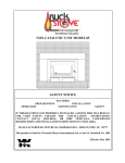
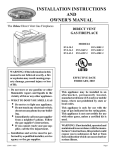
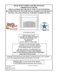
1
DV1000
ZERO CLEARANCE DIRECT VENT GAS FIREPLACE
WITH L.P. (Liquid Propane) or Natural Gas/ Millivolt System
This appliance is not convertible for use with other gases, unless a certified kit is used.
Approved By:
WARNING: If the information in these instructions are not followed exactly, a fire
or explosion may result causing property damage, personal injury or loss of life.
⎯ Do not store or use gasoline or other flammable vapors and liquids in the vicinity of
this or any other appliance.
⎯ WHAT TO DO IF YOU SMELL GAS
•
•
•
•
Do not try to light any appliance.
Do not touch any electrical switch; do not use any phone in your building.
Immediately call your gas supplier from a neighbor’s phone. Follow the gas suppliers instructions.
If you cannot reach your gas supplier, call the fire department.
⎯ Installation and service must be performed by a qualified installer, service agency
or the gas supplier.
This appliance may be installed in an aftermarket, permanently located, manufactured
home (USA only) or mobile home, where not prohibited by local codes.
This appliance is only for use with the type of gas indicated on the rating plate. This
appliance is not convertible for use with other gases, unless a certified kit is used.
INSTALLER: Leave this manual with the appliance.
CONSUMER: Retain this manual for future reference.
JULY 2006
New Buck Corporation
P.O. Box 69
8000 South 226 Highway
Spruce Pine, NC 28777
TABLE OF CONTENTS
Introduction.......................................................................................................................... 2
Firebox Cover Door Removal……………………………………………………………..3
Specifications……………………………………………………………………………...5
Minimum Framing Dimensions……………………………………………………………6
Vent Terminal Clearance…………………………………………………………………..7
Determining The Location…………………………………………………………………8
Minimum Clearances To Combustible Material…………………………………………..8
Direct Vent Termination Installation Instruction………………………………………….9
Pre Installation Instructions………………………………………………………………10
Pipe Installation…………………………………………………………………………...10
Connecting The Venting System To The DV1000……………………………………….11
Optional Rear Horizontal Vent Termination Fireplace Installation…………….………...12
Standard Horizontal Termination Installation…………………………………………….13
Standard Vertical Chase Termination Installation………………………………………..14
Removable Inner Bottom Instructions……………………………………………………15
Gas Supply Connection……………………………………………………………….…..16
Log Placement…………………………………………………………………………….18
Lighting Instructions……………………………………………………………………...20
Wire Diagram (Optional Blower)………………………………………………………...23
Repair Parts/ Manufacturers Address…………………………………………………….24
Cleaning And Maintenance……………………………………………………………….25
Trouble Shooting………………………………………………………………………….27
Replacement Parts………………………………………………………………….30 & 32
Parts Identification………………………………………………………………………..31
Warranty………………………………………………………………………………….33
DANGER: Carbon monoxide poisoning may lead to death!
This appliance is a vented product. This appliance will not produce any gas leakage into
your home if properly installed. This appliance must be properly installed by a qualified service person. The glass door must be properly seated and sealed. If this unit is not properly
installed by a qualified service person with glass door properly seated and sealed, gas leakage can occur.
Carbon Monoxide Poisoning: Early signs of carbon monoxide poisoning resemble the flu,
with headaches, dizziness, or nausea. If you have any of these signs, the cast stove with
burner system may not have been installed properly. Get fresh air at once! Have this appliance and venting system inspected and serviced by a qualified service person. Some people
are more affected by carbon monoxide than others. These include pregnant women, people
with heart or lung disease or anemia, those under influence of alcohol, and those at high altitudes.
Propane/LP gas and natural gas are both odorless. An odor-making agent is added to each of
these gases. The odor helps you detect a gas leak. However, the odor added to these gases
can fade. Gas may be present even though no odor exists.
Make certain you read and understand all warnings. Keep this manual for reference. It is
your guide to safe and proper operation of this cast stove and burner system.
The Model DV1000 Direct Vent Fireplace must be vented using only Magnaflex venting
system (Type: DV4-F.
A manufactured home (USA only) or mobile home OEM installation must confirm
with the Manufactured Home Construction and Safety Standard, Title 24 CFR, Part
3280, or, when such a standard is not applicable, the Standard for Manufactured Home
Installations, ANSI/NCSBCS A225.1, or Standard for Gas Equipped Recreational Vehicles and Mobile Housing, CSA Z240.4.
NOTE: If you have a standard ON/OFF Remote Control or an Optional Thermostat
Remote Control System follow the installation instructions provided with the individual package.
Page 1
INTRODUCTION AND SAFETY FOR
INSTALLATION AND OPERATION
This instruction manual will help you obtain a safe, efficient, dependable installation for your appliance
and vent system. Please read and understand these instructions before beginning your installation.
The model DV1000 is a sealed combustion, air circulating gas appliance designed for residential and
mobile home applications. The appliance must be installed with Magnaflex DV4-F vent system that is
routed to outside atmosphere. It is also listed for bedroom installations.
This appliance is designed to operate on natural or propane gas. A millivolt gas control valve with piezo
ignition system provides safe, efficient operation. No external electrical power is required to operate the
gas valve and burner. 115V AC is required to operate the room air fan.
This appliance complies with National Safety Standards and is tested and listed to ANSI Z21.88-2005
and CSA 2.33-2005.
Installation must conform to local codes. In the absence of local codes, installation must comply with
the current National Fuel Gas Code, ANSI Z223.1/NFPA54, or the National gas and Propane
Installation Code, CSA b149.1...
“WARNING”: Improper installation, adjustment, alteration, service or maintenance can
cause injury or property damage.
SPECIFICATIONS - MODEL DV1000
RATE:
MAX.
MIN.
NAT.
25,000 BTU
20,000 BTU
L.P.
24,000 BTU
20,000 BTU
GAS SUPPLY PRESSURE:
NAT.
MAX. INPUT
10.5" W.C.
MIN. INPUT
*4.0" W.C.
MANIFOLD PRESSURE:
L.P.
13.0" W.C.
11." W.C.
NAT.
3.5" W.C.
L.P.
10.0" W.C.
EFFICIENCY:(With Blower “ON”)
NATURAL GAS
L.P. GAS
88%
88%
FLUE VENT
4" INNER, 7" OUTER; Magnaflex
SAFETY
CSA CERTIFIED PILOT GENERATOR, MILLIVOLT
SYSTEM ACTIVATED WITH SWITCH OR THERMOSTAT.
“WARNING”: This appliance must not be connected to a chimney flue serving a separate
solid-fuel burning appliance.
“Do not use this appliance if any part has been under water. Immediately call a qualified
service technician to inspect the appliance and to replace any part of the control system
and any gas control which has been under water.”
NOTE: the appliance are be kept clear and free from combustible materials, gasoline and
other flammable vapors and liquids.
The flow of combustible and ventilation air not be obstructed.
Page 2
NOTE: Installation and repair should be performed by a qualified service person. The
appliance should be inspected before use and at least annually by a professional service
person. More frequent cleaning may be required due to excessive lint from carpeting,
bedding material, et cetera. It is imperative that control compartments, burners and
circulating air passageways of the appliance be kept clean.
When choosing a location for your DV1000 in your home be sure to provide the following:
Adequate accessibility clearances for servicing and proper operation.
Children and adults should be alerted to the hazards of high surface temperature and
should stay away to avoid burns or clothing ignition.
Young children should be carefully supervised when they are in the same room as the
appliance.
Clothing or other flammable material should not be placed on or near the appliance.
“WARNING: Do not operate appliance with the glass front removed, cracked or
broken. Replacement of the glass should be done by a licensed or qualified service
person.”
“WARNING: Only Logs and Embers supplied with this appliance may be used. No
substitute materials may be used at any time.”
“WARNING: Do not use abrasive cleaners on this appliance. Abrasive
cleaners can damage the painted and glass surfaces of the appliance.”
DV1000 FIREBOX COVER DOOR
REMOVAL INSTRUCTIONS
Glass Care: This appliance has a large cover door bolted to the front area of the firebox. This
cover door must be in place at all times when the appliance is in operation. For the most visual
performance with your appliance it is good to maintain a clean glass on the cover door. To
clean the glass first make sure the glass is cool (not hot), trying to clean the glass when it is hot
can cause personal injury, or damage your cleaning device and the glass. With the glass at room
temperature and the door attached to the appliance, spray the glass are with household glass
cleaner and wipe clean with a lint-free towel. If the inside of the glass needs cleaning follow the
directions on page 4 for removing the cover door, and then clean as you did the front side of the
glass.
“WARNING: Do not abuse the glass cover door such as striking or slamming
shut. The glass can break and cause personal injury.”
CAUTION: If the glass in your appliance becomes broken or cracked,
remove the glass with caution. Wear safety glasses, gloves, shoes and other
protective clothing as needed. See your dealer or the manufacturer for replacement glass cover door.
Page 3
1. The top louver assembly must be removed first. To remove the top louver assembly you must
place your hands one at the bottom left corner and the other at the bottom right corner of the louver assembly. Then with both hands lift up and outwards to release the louver clips from the
stove body. After removing the louver assembly place it in a safe place until time to reinstall.
2. The bottom louver assembly must be in the open position to access the firebox cover door fasteners. The bottom louver assembly is hinged to the bottom of the stove. Place one hand on the
center of the top louver and pull slowly out and downward to open.
3. Before removing the firebox cover door you must remove the six (6) 1/4-20 nuts located across
the top of the door and the bottom of the door. After removing the nuts you must slowly pull the
door outward and completely off the studs. Place the door in a safe place until time to reinstall,
the glass is breakable.
NOTE: The Firebox Cover Door must be removed to access the pilot assembly located in the right
rear corner of the firebox area, and to access the burner pan located in the bottom center of the
firebox area. The door must also be removed when placing the logs and embers.
4. To replace the cover door, reverse steps 3 thru 2.
1. TOP LOUVER ASSEMBLY
3. FIREBOX COVER DOOR
2. BOTTOM LOUVER ASSEMBLY
FIGURE 1
RIGHT SIDE
LEFT SIDE
FRONT
#1 SIDE VIEW OF
LOUVER ASSEMBLY
AND CLIP.
#1
SLOT IN STOVE BODY FRONT FOR LOUVER ASSEMBLY CLIP TO SECURE TO
STOVE BODY.
1/4-20 NUTS
WARNING: “Do not operate
appliance with the glass front
removed, cracked or broken.
Replacement of the glass should be
done by a licensed or qualified
service person.”
#3
#2
Replace the entire cover door assembly if glass
becomes defective with part # PO COVDOR1.
Page 4
DV1000 SPECIFICATIONS
38-1/8”
36”
33-1/2”
16-15/16”
TOP STANDOFF(S)
SIDE STANDOFF(S)
27-1/8”
REAR STANDOFF
13-9/16”
16-1/2”
15-1/8”
10-5/32”
24-1/4”
FIGURE 2
2-1/2”
6”
NOTE: When the appliance is installed directly on carpeting, tile or
other combustible material other than wood flooring, the appliance
shall be installed on a metal or wood panel extending the full width
and depth of the appliance.
Page 5
MINIMUM FRAMING DIMENSIONS
2-1/2”
36-1/8”
17
”
37
-7
/1
6”
38
-1
(F
/8
ra
”(
m
in
Fi
g*
ni
sh
)
56
ed
-3
)
/4
*
”
40-1/8”
/2”
6-1
16”
-7/
7
3
17” *
RIGHT
SIDE *
FRONT *
37-7/16” *
LEFT
SIDE *
Note: “Front side and top standoff (s) are permanently attached
to the front trim panels. The
front trim panels are attached by
the manufacturer and must not
be removed or altered in anyway
for any reason.”
17” *
Combustible Adjacent
Side Wall.
37-7/16”*
6”
FIGURE 3
Note: “Only trim kit(s) supplied by the manufacturer shall be used in the installation of
this appliance.”
Page 6
VENT TERMINAL CLEARANCES
FIGURE 4
Page 7
DETERMINING THE LOCATION FOR DV1000
Note: The installation must conform with local codes or, in the absence of local codes, with
the National Fuel Gas Code, ANSI Z223.1/NFPA 54, or the Natural Gas and Propane Installation Code, CSA B149.1.
This appliance may be installed in an aftermarket, permanently located, manufactured
home (USA only) or mobile home, where not prohibited by local codes.
This appliance is only for use with the type of gas indicated on the rating plate. This appliance is not convertible for use with other gases, unless a certified kit is used.
Due to high temperatures, the appliance should be located out of traffic and away from furniture and draperies.
The appliance, when installed, must be electrically grounded in accordance with local codes
or, or in the absence of local codes, with the National Electrical Code, ANSI/NFPA 70, or the
Canadian Electrical Code CSA C22.1.
The Model DV1000 Direct Vent Fireplace must be vented using only Magnaflex DV4-F venting
system. All warranties will be voided and tech service suspended and serious fire, health or
safety hazards may result from using any other venting system than the tested and approved
Magnaflex DV4-F system with this appliance.
You must check the Vent Termination Clearance requirements from decks, windows, soffits, gas
regulators, air supply inlets, and public walkways, etc. as shown in these instructions and specified by local building codes (see figure 4, page 7). This gas appliance must be vented directly to
the outside of the building. This gas appliance must not be connected to a chimney flue serving a
separate solid-fuel burning appliance. Preparation for electrical connection and gas supply must
be made before the appliance is located. (see figure 3, page 6 for framing dimensions)
MINIMUM CLEARANCE TO COMBUSTIBLE MATERIAL FROM FIREPLACE AND
VENT SURFACES:
Sides, Back, Bottom and Top of appliance (standoffs)
Recessed depth to back of front trim
Recessed depth to front of front trim
Diameter of vent pipe
Top of appliance to ceiling
0 inch
17 inches
17-1/2 inches
2 inches
54 inches
MANTEL CLEARANCES……
W=Width (@) H=Height
DRYWALL
WALL BOARD
W
STUD
H
STANDOFF
3/4” ——————–2”
2”———————–2”
4”———————–10”
6”———————–12”
8”———————–14”
10”———————16”
12”———————18”
TOP EDGE OF
UNITS TRIM
DV1000
FIGURE 5
Page 8
NOTE: Adequate clearances around air openings
into the combustion chamber. Do Not cover any of
the louvered areas on this
appliance front, or the glass
cover door.
DV1000
DIRECT VENT TERMINATION
INSTALLATION INSTRUCTIONS
(MAGNAFLEX)
Read the instructions in this manual completely before installing the DV1000 appliance with
the Magnaflex vent system. Magnaflex Venting systems are packaged with installation instructions, the instructions must be followed exactly for your safety and to prevent voiding the warranty of your appliance and venting system.
The DV1000 will operate safely when installed in accordance with this instruction manual.
Read all instructions before starting installation, then follow these instructions carefully to
maximize fireplace performance and safety. Report damaged parts to your dealer.
Any common venting of the gas appliance using DV vent kit with other gas appliances is not
allowed. Do not connect this appliance to a chimney flue serving a separate solid fuel-burning
appliance.
WARNING: Always maintain minimum clearances around vent systems. The minimum
clearance to combustibles for horizontal vent pipe is 3 inches at the top and 1 inch at the
bottom of the vent system until the flue penetrates the nearest vertical wall.
FOR WALL FIRESTOPS AND VERTICAL RUNS ONLY, maintain a 1 inch minimum
clearance from all sides of the vent. Do not pack the open air spaces around the fireplace
or flue with insulation or other materials. Any horizontal run must have a 1/4” rise for
every one (1) foot of run towards the vent termination. Never install the vent level or
downward.
WARNING: Contact your Local Building and Fire Officials about restrictions and installation inspections in your area.
IMPORTANT SAFETY INFORMATION
∗
∗
∗
∗
∗
∗
∗
The termination cap MUST be vented directly to the outside. The termination kit MUST
NEVER be connected to a chimney flue(s) servicing a separate solid-fuel burning appliance
or any other appliance.
Termination cap MUST NOT be recessed into a wall or siding.
The flexible vent pipe cannot be intermingled with any of the rigid vent pipe section. DO
NOT connect two sections of flexible vent pipe together to achieve a longer length without
approved connectors.
Horizontal runs must be supported every 3 feet using wall straps. Vertical runs must be supported every 8 feet using wall straps. Slip wall straps loosely on to pipe. Attach straps to
framing members using nails or screws. Tighten nut/bolt to secure pipe.
The fireplace and venting system should be inspected before initial use and at least annually
by a qualified field service person. Inspect external vent cap on a regular basis to make sure
that no debris is interfering with the airflow. Inspect entire venting system to ensure proper
function.
Vent connections should overlap a minimum of 1” for proper sealing.
Always stretch and secure venting with metal strapping secured with nails (nails and strapping not supplied) to ensure that the horizontal runs remain true.
Page 9
∗
∗
∗
The termination cap must be positioned so that the embossed arrow is pointed up.
Ensure that the venting system exits the structure through a sidewall or similar structure and
does not terminate less than 12 inches (305mm) above the ground.
Ensure that the venting system is located above the snow line in geographical areas where snow
accumulates.
PRE-INSTALLATION INFORMATION:
Items Required For Installation:
Tools
Phillips Screwdriver
Measuring Tape
Hammer
Electric Drill and Bits
Saw and/or saber saw
Pliers
Level
Square
Building Supplies
Framing Materials
Wall Finishing Materials
Caulking Material (Noncombustible)
Silicone Sealant (High Temp.)
PIPE INSTALLATION:
Note: If you haven’t read pages 1 thru 9 completely “STOP”, and read them “NOW”.
1. Unpack vent components and check all items for shipping damage.
2. Locate Magnaflex DV4-F Installation Instructions and follow them exactly.
3. If Wall Straps are needed for your installation, determine the number of straps needed and obtain them before beginning the installation process.
4. The pipe assembly consist of (2) two pipes. The enter pipe is the 4” flue pipe, and the outer pipe
is the 7” vent pipe. The (2) two pipes are separated by spacer springs, if any of the spacer
springs should come off while installing the pipe you must replace the before continuing (see
figure 6).
5. Follow the vent manufactures instruction for placing the Spacer Springs onto the 4” flue pipe.
6. The flexible vent pipe cannot be intermingled with any rigid vent pipe section. DO NOT connect two sections of flexible vent pipe together to achieve a longer length without approved
connectors.
7. Use the 4” Clamps provided with your kit to attach the flue pipe to the appliance and to the termination cap. Also use the 7” Clamps provided with your kit to attach the vent pipe to the adaptor collar after it has been attach to the appliance and to the termination cap also. (see page 11,
figure 7)
CLAMP
SPACER
SPRING
FIGURE 6
7” FLEX
OUTER VENT
PIPE
CLAMP
Page 10
4” FLEX FLUE
PIPE
8. Plan your installation. Set the appliance in place and survey how best to vent the appliance. Select the appropriate termination kit for the installation. Read the vent pipe manufacturers instructions and the appliance manufacturers instruction manual before either. After vent configuration has been decided, stretch the flex components out, then trim off what will not be needed.
A temporary fit up will determine this. Once the vent length has been determined and the necessary parts are obtained for the installation you can begin installing the venting system.
•
Follow the Installation Instructions provided with the Magnaflex DV4-F venting kit.
CONNECTING OR RECONNECTING THE VENTING SYSTEM TO THE Model DV1000
∗
After following the venting manufactures instructions, and you have installed the piping up
to the area of the appliance. Continue with the installation using the vent manufactures instructions and the instructions and illustrations in this manual.
A. Add High temperature
sealant (caulk) to the
inside (inner) edge of
the 4” flexible flue
pipe.
B. Place the 4” flexible
flue pipe through the
center of the flex
adapter collar w/
gasket , leaving the
adapter collar unattached to the appliance
and pulled up the pipe
out of the way. With
the 4” clamp also over
the 4” flex flue and
loose, push the 4” flex
flue pipe onto (over)
the 4” flue adapter collar until it is properly
seated (about 1” to 11/4”).
OUTER 7” VENT PIPE
INNER 4” FLUE PIPE
SELF TAPPING SCREWS
FLEX ADAPTER COLLAR WITH
GASKET (Gasket may come attach
to the collar from the manufacturer)
APPLIANCE 4” FLUE ADAPTOR
COLLAR (FLUE EXIT). PREINSTALLED BY THE APPLIANCE
MANUFACTURER.
C. Place the 4” clamp over the section of 4” flex flue
pipe that is pushed onto the flue adapter and
tighten the clamp.
D. Seat the flex flue adapter collar with gasket on to
the appliance centering around the flue adapter
and secure it to the appliance using (4) four of the
self tapping screws provided with the venting kit.
E. Next place the 7” clamp over the end of the 7” flex
vent pipe and leave it loose for now.
F. With both hands pull the 7” flex vent pipe onto
(over) the flex flue adapter and push it onward
until it is properly seated.
G. Place the 7” clamp over the section of 7” flex vent
pipe you just seated and tighten.
NOTE: TOP VENT INSTALLATION SHOWN ABOVE. FOLLOW THE SAME INSTRUCTIONS FOR OPTIONAL REAR
VENT INSTALLATION.
FIGURE 7
Page 11
OPTIONAL DV1000 REAR HORIZONTAL VENT TERMINATION FIREPLACE
This appliance has a rear vent termination option. (you must purchase a DV1000 with this option from your dealer) Use termination kit #PP-DVVK-4F-1 only. This installation option can
only be used exactly as shown in figure 5. Follow the direction provided with the termination
kit. (see Horizontal Air Termination Installation page )
* 20” “From the rear
of the unit to the outside wall.”
3/4” WALL BOARD
2” x 4” WALL STUD
3/4” BLACK EXTERIOR WALL BOARD
2” x 4” x 8” BRICK EXTERIOR SURFACE
DEFLECTOR SHIELD
DV1000
* 8”
3” min.
HORIZONTAL
TERMINATION CAP
* “DIMENSION(S) MUST
BE EXACTLY AS SHOWN
IN THIS EXAMPLE.”
1” min.
FILL ANY CRACKS OR GAPS
WITH HIGH TEMPERATURE
CAULK
* 24-1/4”
Flex Pipe
NOTE: This is only an example.
Walls may vary in materials and
construction type.
FIGURE 8/ OPTIONAL REAR VENT TERMINATION EXAMPLE.
9-1/2” WALL
CORNER TERMINATION WITH OPTIONAL REAR VENT
20”
The maximum length for a
corner installation is 20”,
with a minimum 8” rise.
20”
FIGURE 9
Page 12
8”
DV1000 STANDARD HORIZONTAL TERMINATION INSTALLATIONS
HORIZONTAL
TERMINATION CAP
ASSEMBLY
12”
45-1/2”
10-1/2” From Rear
Standoff To Outside
Wall.
MINIMUM INSTALLATION
NOTE: Horizontal pipe installations must be
supported with Wall Straps every 3 feet.
WALL STRAPS
56”Max. & 49-1/2” Min.
*16”
53” Max. & 11” Min.
From Rear Standoff To
Outside Wall.
MAXIMUM INSTALLATION
FIGURE 10
Page 13
DV1000 STANDARD VERTICAL CHASE TERMINATION
INSTALLATIONS
VERTICAL TERMINATION CAP
ASSEMBLY
30 FT.
MAX.
WALL STRAPS
NOTE: Vertical pipe installations must
be supported with Wall Straps every
8 feet.
FLEX PIPE (ONLY)
3 FT.
MIN.
DV1000 FRONT
FIGURE 11
Page 14
REMOVABLE INNER BOTTOM PAN ASSEMBLY
The DV1000 is equip with a removable Inner Bottom Pan Assembly for service purposes only. The burner
control assembly should only be accessed by this procedure by a qualified service technician, or by the
manufacturer. Follow the instructions and diagrams below.
1. Turn gas OFF at equipment shut OFF
valve, and disconnect union located at
Right side of control valve. Remove
Cover Door, see pages 3 & 4.
2. Remove the 4 screws located on top of
the Burner Pan area which attach the
Burner Pan to the Firebox Deck.
3. Remove the 4 screws located at the
back of the Firebox area which attach
the Firebox Deck to the back of the
Firebox.
4. Lift the Firebox Deck upward and outwards. And then gently lift the Burner
and Ventura assembly upward from
top of the Orifice assembly.
5. Next locate the 26 screws pattern
around the edge of the Inner Bottom
Pan Assembly and remove them.
6. Push upward from the bottom of the
Inner Bottom Pan ( do not
2
3
4
REV.
DATE
DATE
5
push on the gas valve control or any of the other components).
7. A gasket is located on the bottom edges of the Inner Bottom
Pan assembly. If this gasket is damaged during this process it
must be replaced with a gasket from the manufacture and
resealed with high-temperature caulk weather damaged or
6
7
FIGURE 12
Page 15
GAS SUPPLY CONNECTION
CHECK GAS TYPE
Use proper gas type for the burner system you are installing. If you have conflicting gas types, do
not install burner system. See dealer where you purchased the stove and burner system for proper
burner system according to your gas type.
INSTALLING GAS PIPING TO APPLIANCE
Installation Items Needed
Before installing the appliance make sure you have the items listed below.
•
External regulator (supplied by installer)
•
Piping (check local codes)
•
Sealant (resistant to propane/LP gas)
Warning: A qualified installer or
•
Equipment shutoff valve *
service person must connect burner
•
Test gauge connection *
system to gas supply. Follow all local
codes.
•
Sediment trap
•
Tee joint
•
Pipe wrench
∗ An CSA design-certified equipment shutoff valve with 1/8" NPT tap is an acceptable alternative
to test gauge connection. Purchase the CSA design-certified equipment shutoff valve from your
dealer.
CAUTION: For propane/LP units, never connect burner system directly to the propane/LP
supply. This burner system requires an external regulator (not supplied). Install the external
regulator between the burner system and propane/LP supply.
CAUTION: Use only new, black iron or steel pipe. Internally-tinned copper tubing may be
used in certain areas. Check your local codes. Use pipe of 1/2" diameter or greater to allow
proper gas volume to burner system. If pipe is too small, undue loss of pressure will occur.
For propane/LP connections only, the installer must supply an external regulator. The external
regulator will reduce incoming gas pressure. You must reduce incoming gas pressure to between
11 and 14 inches of water. If you do not reduce incoming gas pressure, burner system regulator
damage could occur. Install external regulator with the vent pointing down as shown in. Pointing
the vent down protects it from freezing rain or sleet.
Installation must include an equipment shutoff valve, union, and plugged 1/8" NPT tap. Locate
NPT tap within reach for test gauge hook up. NPT tap must be upstream from burner system.
IMPORTANT: Install main gas valve (equipment shutoff valve) in an accessible location. The
main gas valve is for turning on or shutting off the gas to the appliance.
Check your building codes for any special requirements for locating equipment shutoff valve to
stoves.
Apply pipe joint sealant lightly to male threads. This will prevent excess sealant from going into
pipe. Excess sealant in pipe could result in clogged burner system valves.
We recommend that you install a sediment trap/drip leg in supply line. Locate sediment trap/drip
leg where it is within reach for cleaning. Install in piping system between fuel supply and burner
system. Locate sediment trap/drip leg where trapped matter is not likely to freeze. A sediment trap
traps moisture and contaminants. This keeps them from going into burner system gas controls. If
sediment trap/drip leg is not installed or is installed wrong, burner system may not run properly.
Page 16
Pressure Testing Gas Supply Piping System
Note: The appliance and its appliance main valve must be disconnected from the gas supply piping
system during any pressure testing of that system at test pressures in excess of 1/2 psi. (3.5 kPa).
The appliance must be isolated from the gas supply piping system by closing its equipment shutoff
valve during any pressure testing of the gas supply piping system at test pressures equal to or less
than 1/2 psi. (3.5 kPa).
Test Pressures In Excess of 1/2 PSIG (3.5 kPa)
1. Disconnect appliance with its appliance main gas valve (control valve) and equipment shutoff
valve from gas supply piping systems. Pressures in excess of 1/2 psig (3.5 kPa) will damage
burner system gas regulator.
2. Cap off open end of gas pipe where equipment shutoff valve was connected.
3. Pressurize supply piping system by either opening propane/LP supply tank valve for propane/LP
gas burner system or opening main gas valve located on or near gas meter for natural gas burner
system, or using compressed air.
4. Check all joints of gas supply piping system. Apply commercial leak test solution to all gas
joints. Bubbles forming show a leak. Correct all leaks at once.
5. Reconnect burner system and equipment shutoff valve to gas supply. Check reconnected fittings
for leaks.
Test Pressures Equal To or Less Than 1/2 PSIG (3.5 kPa)
1. Close equipment shutoff valve.
2. Pressurize supply piping system by either opening propane/LP supply tank valve for propane/LP
gas burner system or opening main gas valve located on or near gas meter for natural gas burner
system, or using compressed air.
3. Check all joints from propane/LP supply tank or gas meter to equipment shutoff valve (see
Figure 34, page 17 for propane/LP or Figure 35, page 17 for natural). Apply commercial leak test
solution to all gas joints. Bubbles forming show a leak. Correct all leaks at once.
Warning: Test all gas piping and
connections for leaks after
installing or servicing. Correct all
leaks at once.
Union
WARNING: Never use an open
flame to check for a leak. Apply
commercial leak test solution to all
gas joints. Bubbles forming show a
leak. Correct all leaks at once.
CSA/AGA DesignCertified Equipment
Shutoff Valve With
1/8" NPT Tap
NOTE: The minimum inlet gas supply
pressure for the purpose of input adjustment.
NOTE: The maximum inlet gas supply
pressure.
LP
PRESSURE:
10.0" W.C.
*MIN. INLET 11.0" W.C.
MAX. INLET 13.0" W.C.
Gas Control
NATURAL
3.5" W.C.
4" W.C.
10.5" W.C.
EQUIPMENT
SHUTOFF
VALVE
OPEN
CLOSED
FIGURE 13
Page 17
EQUIPMENT SHUTOFF VALVE
CAUTION
Hot while in operation. Do Not Touch severe burns may result. Keep children, clothing,
furniture, gasoline, and other liquids having flammable vapors away.
WARNING: Improper installation, adjustment, alteration, service or maintenance can cause
property damage, personal injury, or loss of life. Refer to owner’s information manual
provided with this appliance. Installation and service must be performed by a qualified
installer, service agency, or the gas supplier.
IMPORTANT: Always operate the appliance at the completely ON or the completely OFF
positions. Never use the heater at a setting between these positions as this can result in
improper combustion and excessive carbon monoxide emissions.
Keep burner and control compartment clean.
accompanying heater.
See installation and operating instructions
DV1000 LOG PLACEMENT
Before placing the Logs and Embers you must first remove the Firebox Cover Door from the
appliance, see pages 3 and 4. After removing the cover door follow the instructions below and
on the following page. (The log placement is exactly the same for the Pine log set as for the
Oak log set.
1. Carefully open the box containing the logs. Remove the #1 log (Rear Log) and place it in
the rear center of the firebox behind the log holders located on the left and right sides.
2. Next remove the #2 log (Left Middle Log) and place it on the 2 pins (screws) located on the
left hand side of the burner.
3. Now remove the #3 log (Right Middle Log) and place it on the pins (screws) located on the
right hand side of the burner.
4. Locate the #4 log (Left Front Log) and place it on the pin (screw) located on the left front
bottom corner of the firebox. Next place the other end of the log on the pin (pins) located on
the left side of the top of the #1 log.
5. Place the large end of the #5 log (Front Center Log) on the pin (screw) located in the front
bottom center of the firebox. Place the other end of the #5 log on the pin located at the top
center of the #1 log.
6. Next place the #6 log (Right Front Bottom Log) on the pins (screws) located on the left
hand side of the bottom of the firebox.
7. Place the #7 log (Right Front Top Log) on to the pins located in the top of the #6 log.
8. Provided with your log set is a package of Glowing Embers (rock wool). Open the package
and tare off small pieces of the wool material and place it over the small holes (ports) located on the front burner pan in front of logs #5 and #6. Cover the entire section of holes
(ports). *Replacement of loose (Glowing Embers) must be purchased from the original
manufacturer and application of excess loose material may adversely affect performance of the heater.
NOTE: “Wash your hands immediately after coming in contact with the wool material.
The wool can cause slight itching or burning in some cases, avoid any contact with eyes.”
Page 18
FIGURE 14
“Apply loose material per instructions manual. DO NOT apply extra material or material not supplied with the heater. Replace only with material from your Buck Stove dealer or from New Buck
Corporation.
WARNING: Failure to position the parts in accordance with these diagrams or failure to use
only parts specifically approved with this heater may result in property damage or personal
injury.
This appliance must be installed in accordance with local codes if any. If none, then follow the
National Fuel Gas Code, ANSI Z223.1/NFPA 54, or Natural Gas and Propane Installation
Codes, CSA -B149.1.
“CAUTION: Do not operate the appliance with glass removed, cracked or broken. Replacement of the panel(s) should be done by a licensed or qualified service person.”
Page 19
FOR YOUR SAFETY READ BEFORE
LIGHTING
WARNING: If you do not follow these instructions exactly, a fire or explosion may result
causing property damage, personal injury, or loss of life.
A. This appliance has a pilot which must be lighted by hand. When lighting the pilot, follow
these instructions exactly.
B. BEFORE LIGHTING smell all around the appliance area for gas. Be sure to smell next to
the floor because some gas is heavier than air and will settle to the floor.
WHAT TO DO IF YOU SMELL GAS:
* Do not try to light any appliance.
* Do not touch any electric switch; do not use any phone in your building.
* Immediately call your gas supplier from a neighbor’s phone. Follow the gas supplier’s
instructions.
* If you cannot reach your gas supplier, call the fire department.
C. Use only your hand to push in or turn the gas control knob. Never use tools. If the knob
will not push in or turn by hand, don’t try to repair it, call a qualified service technician. Force
or attempted repair may result in a fire or explosion.
D. Do not use this appliance if any part has been under water. Immediately call a qualified
service technician to inspect the appliance and to replace any part of the control system and any
gas control which has been under water.
Page 20
LIGHTING INSTRUCTIONS
1.
2.
3.
4.
5.
STOP! Read the safety information on this label.
“Set the thermostat to lowest setting.”
“Turn off all electric power to the appliance.”
Open access cover door.
Turn control knob clockwise
to the “OFF” position.
CONTROL KNOB
IN
OUT
PI
L OT
NOTE: Knob cannot be turned from “PILOT” to “OFF” unless knob is pushed in slightly.
DO NOT FORCE.
6. “Wait five (5) minutes” to clear out any gas. Then smell for gas, including near the floor.
If you smell gas, STOP! Follow “B” in the safety information label. If you don’t smell gas,
go to the next step.
7. Pilot is located between the front and rear burner.
8. Turn control knob counter clockwise
to the “Pilot” position.
9. Press in control knob. With control knob pressed in, immediately push and release ignitor
button. This will light the pilot.
NOTE: * If the knob does not pop up when released, “Stop” and immediately call your
service technician or gas supplier.
* “If the pilot will not stay lit after several tries, turn the gas control knob to “OFF”
and call your service technician or gas supplier.”
10. Continue to hold the control knob pressed in for one (1) minute after the pilot is lit.
Release the control knob and it will pop back up. Pilot should remain lit. If it goes out,
repeat steps 5 thru 10.
11. Turn control knob counter clockwise
to “ON” position.
12. Close access cover door.
13. Turn on all electric power to the appliance.
Page 21
14. If using unit without wall thermostat place (AUTO/OFF/MANUAL) switch
in the “MANUAL” position. If using wall thermostat place (AUTO/OFF/
MANUAL) switch in the “AUTO” position, and place wall thermostat to a
setting higher than the room temperature.
PIEZO IGNITOR BUTTON LOCATED TO THE LEFT, BESIDE
THE SIDE OF THE GAS VALVE
TO TURN OFF GAS TO APPLIANCE
1.
2.
3.
4.
Set the thermostat to lowest setting (if used).
Turn off all electric power to the appliance if service is to be performed.
Open access cover door.
Push in gas control knob slightly and turn clockwise
to “OFF.” Do not
force.
5. Close access cover door.
Page 22
WIRING DIAGRAM
MOTOR
THERMOSTAT
JUMPER
JUMPER
JUMPER
GREEN
WHITE
BLACK
RHEOSTAT
BLACK
POWER CORD
Optional Blower Kit: #MA DV1000714. (Standard with XL package.)
NOTE: “If any of the original wire as supplied with the gas appliance must be replaced, it
must be replaced with a wire of at least a 105o C. temperature rating.”
CAUTION: Label all wires prior to disconnection when servicing controls. Wiring errors can
cause improper and dangerous operation.
Verify proper operation after servicing.
WARNING:
ELECTRICAL GROUNDING INSTRUCTION:
THIS APPLIANCE IS EQUIPPED WITH A THREE-PRONG (GROUNDING) PLUG
FOR YOUR PROTECTION AGAINST SHOCK HAZARD AND SHOULD BE
PLUGGED DIRECTLY INTO A PROPERLY GROUNDED THREE-PRONG
RECEPTACLE.
WARNING: DO NOT USE A BLOWER INSERT , HEAT EXCHANGER OR OTHER
ACCESSORY NOT APPROVED FOR USE WITH THIS HEATER.
FOR YOUR SAFETY : DO NOT STORE OR USE GASOLINE OR OTHER FLAMMABLE VAPORS
AND LIQUIDS IN THE VICINITY OF THIS OR ANY OTHER APPLIANCE.
Page 23
BURNER ORIFICES SIZES:
“For natural gas when equipped with No. 46 drill size orifice.”
“For propane when equipped with No. 1.50mm drill size orifice.”
NOTE: “This appliance equipped only for altitudes 0-2000 feet (0-610m).”
SERVICING
Repair and replacement work should only be performed by a qualified service technician.
Always shut off the gas supply and make sure heater is cool before beginning any service
operation. Check for gas leaks after servicing.
REPAIR PARTS
A parts list with exploded view follows. Always include correct name, part number, and model
number of the heater when ordering service parts. Please contact your local dealer or distributor
when ordering . If one is not available, you may contact.
New Buck Corporation
8000 Highway 226 South
Spruce Pine, NC 28777
Page 24
CLEANING AND MAINTENANCE
Glass Care: This appliance has a large cover door bolted to the front area of the firebox. This cover
door must be in place at all times when the appliance is in operation. For the most visual performance with your appliance it is good to maintain a clean glass on the cover door. To clean the glass
first make sure the glass is cool (not hot), trying to clean the glass when it is hot can cause personal
injury, or damage your cleaning device and the glass. With the glass at room temperature and the
door attached to the appliance, spray the glass are with household glass cleaner and wipe clean with
a lint-free towel. If the inside of the glass needs cleaning follow the directions on page 4 for removing the cover door, and then clean as you did the front side of the glass.
During start-up it is normal for condensation to form on the inside of the glass causing lint, dust, and
other airborne particles to cling to the glass surface. During initial start-up a slight film may form on
the glass due to paint curing. The glass should be cleaned several times with a non-ammonia, nonabrasive household cleaner and warm water after the first two weeks of operation. Thereafter, clean
the glass two or three times during each heating season, depending on the usage and circumstances
present.
“WARNING: Do not abuse the glass cover door such as striking or slamming shut. The glass
can break and cause personal injury.”
Any safety screen or guard removed for servicing an appliance must be replaced prior to operating the appliance.
CAUTION: If the glass in your appliance becomes broken or cracked, remove the glass with
caution. Wear safety glasses, gloves, shoes and other protective clothing as needed. See your
dealer or the manufacturer for replacement glass.
PILOT AND BURNERS
Periodic visual check of pilot and burner flames
•
Burner and controls should be cleaned with compressed air to remove dust, dirt, or lint.
Use a vacuum cleaner or small, soft bristled brush to remove excess dust, dirt, or lint.
PILOT
BURNER/ AIR SHUTTER
Pilot Burner
Flame should
engulf the tip end
of the Thermopile and the Thermocouple, and
should be constant. The flame
should be
Blue in color. And 3/4” to 1” in height.
Thermocouple
Thermopile
Ignitor Electrode
Incorrect flame patterns
Correct flame pattern
Burner Flame Pattern
Page 25
LOGS:
•
If you remove logs for cleaning, refer to Installing Logs, page 18 to properly replace logs.
•
Use a vacuum cleaner to remove any carbon buildup on logs.
Replace logs if broken. See Replacement Parts on page 29.
• Also use a vacuum cleaner to remove any particles on the Burner Pan.
EMBERS:
“Apply loose material per instructions manual. DO NOT apply extra material or material not
supplied with the heater. Replace only with material from your Buck Stove dealer or from New
Buck Corporation.
BURNER PAN ASSEMBLY
BURNER PAN
BURNER PORTS
Philllips Head Screw
AIR SHUTTER
(To Gain Access To The Air Shutter, Remove
The Cover Plate On The Orifice Box Located In
The Burner Control Compartment Directly Under The Center Of The Burner Pan)
VENTURA ASSEMBLY
Air Shutter Slot (Opening)
VENTING SYSTEM
Periodic examination of venting systems by a qualified agency.
1. Check areas of venting system that are exposed to the weather for corrosion (rust spots or streaks
and, in extreme cases, holes). Have these items replaced immediately by a qualified service person.
2. Remove the vent cap and shine a flashlight into the vent. Remove any foreign material.
3. Check for evidence of excessive condensation. Continuous condensation can cause corrosion of
caps, pipes, and fittings and can be caused by having excessive lateral runs, too many elbows, or
exterior portions of the system being exposed to cold weather.
4. Inspect joints to verify that no pipe section or fitting has been disturbed and loosened. Check mechanical supports such as wall straps for rigidity.
Page 26
WARNING: Turn off burner system
and let cool before servicing. Only a
qualified service person should service
and repair burner system or stove.
CAUTION: Never use a wire, needle,
or similar object to clean pilot. This
can damage pilot unit.
OBSERVED PROBLEM
POSSIBLE CAUSE
REMEDY
When ignitor button is pressed, there is no
spark at pilot
1.
1.
Reconnect ignitor cable
2.
Ignitor electrode not connected to
ignitor cable
Ignitor cable pinched or wet
2.
3.
Piezo ignitor nut is loose
3.
4.
5.
6.
7.
Broken ignitor cable
Bad piezo ignitor
Ignitor electrode broken
Ignitor electrode positioned wrong
4.
5.
6.
7.
Free ignitor cable if pinched by any
metal or tubing. Keep ignitor cable
dry
Tighten nut holding piezo ignitor.
Nut is located behind the mounting
bracket
Replace ignitor cable
Replace piezo ignitor
Replace pilot assembly
Replace pilot assembly
1.
Gas supply turned off or equipment
shutoff valve closed
Gas control knob not in PILOT
position
Gas control knob not pressed in
while in PILOT position
Air in gas lines when installed
1.
5.
6.
Depleted gas supply (propane/LP
models only)
Pilot is clogged
7.
Gas regulator setting is not correct
7.
1.
2.
Gas control knob not fully pressed in
Gas control knob not pressed in long
enough
Equipment shutoff valve not fully
open
Pilot flame not touching
thermocouple, which allows
thermocouple to cool, causing pilot
flame to go out. This problem could
be caused by one or both of the
following:
A. Low gas pressure
B. Dirty or partially clogged pilot
Thermocouple connection loose at
control valve
Thermocouple damaged
Control valve damaged
1.
2.
TROUBLESHOOTING
Note: All troubleshooting items are listed
in order of operation.
When ignitor button is pressed, there is
spark at pilot but no ignition
2.
3.
4.
5.
Pilot lights but flame goes out when
control knob is released
3.
4.
5.
6.
7.
24
Page 27
2.
3.
4.
6.
Turn on gas supply or open
equipment shutoff valve
Turn gas control knob to PILOT
position
Press in gas control knob while in
PILOT position
Continue holding down gas control
knob. Repeat igniting operation until
air is removed
Contact local propane/LP gas
company
Clean pilot (see Cleaning and
Maintenance, page 25 or replace
pilot assembly
Replace gas control
3.
Press in gas control knob fully
After pilot lights, keep gas control
knob pressed in 30 seconds
Fully open equipment shutoff valve
4.
A) Contact local gas company
B) Clean pilot (see Cleaning and
Maintenance, page 25) or replace
pilot assembly
5.
6.
7.
Hand tighten until snug, then tighten
1/4 turn more
Replace thermocouple
Replace control valve
OBSERVED PROBLEM
POSSIBLE CAUSE
REMEDY
Burner does not light after pilot is lit
1.
Burner orifice clogged
1.
2.
Inlet gas pressure is too low
2.
3.
3.
4.
Thermopile leads disconnected or
improperly connected
Thermopile is defective
4.
1.
Manifold pressure is too low
1.
2.
Burner porting or orifice clogged
2.
1.
Burner orifice is clogged or damaged
1.
2.
3.
Damaged burner
Gas regulator defective
2.
3.
Slight smoke or odor during initial
operation
1.
Residues from manufacturing
processes and logs curing
1.
Problem will stop after a few hours
of operation
Burner system produces a whistling noise
when burner is lit
1.
Turning gas control knob to HI
position when burner is cold
1.
2.
Air in gas line
2.
3.
Dirty or partially clogged burner
orifice
3.
Turn gas control knob to LO
position and let warm up for a
minute
Operate burner until air is removed
from line. Have gas line checked by
local propane/LP or natural gas
company
Clean burner (see Cleaning and
Maintenance, page 25) or replace
burner orifice
1.
Flame impingement on logs
1.
2.
Debris around burner air mixer
2.
Burner system produces a clicking/ticking
noise just after burners are lit or shut off
1.
Metal expanding while heating or
contracting while cooling
1.
This is common. If noise is
excessive, contact qualified service
person.
Remote does not function
1.
Battery is not installed or battery
power is low
1.
Replace 9-volt batteries in receiver
and remote control
Delayed ignition burner
Burner backfiring during combustion
Glass soots
Page 28
Clean burner (see Cleaning and
Maintenance, page 25 or replace
burner orifice
Contact local propane/LP or natural
gas company
Reconnect leads (see Wiring
Diagram, page 30
Replace thermopile
Contact local propane/LP or natural
gas company
Clean burner (see Cleaning and
Maintenance, page 25 or replace
burner orifice
Clean burner (see Cleaning and
Maintenance, page 25) or replace
burner orifice
Replace damaged burner
Replace gas control
Adjust the log set so that the flame
does not excessively impinge on it
Inspect the opening at the base of the
burner to see that it is NOT packed
with any type of material
TROUBLESHOOTING
Continued
WARNING: If you smell gas
•
Shut off gas supply.
•
Do not try to light any appliance.
•
Do not touch any electrical switch; do not use any phone in your building.
•
Immediately call your gas supplier from a neighbor’s phone. Follow the gas
supplier’s instructions.
•
If you cannot reach your gas supplier, call the fire department.
OBSERVED PROBLEM
POSSIBLE CAUSE
REMEDY
Burner system produces unwanted odors
1.
Gas leak. See Warning statement
above
1.
Locate and correct all leaks (see
Checking Gas Connections, pages 15
thru 17
Burner system shuts off in use
1.
High or gusting winds
1.
2.
Low line pressure
2.
3.
Pilot is partially clogged
3.
4.
Inner vent pipe leaking exhaust
gasses into system
4.
5.
Glass too loose and air tight gasket
leaks in corners after usage
Bad thermopile or thermocouple
Improper vent cap installation
5.
Burner system has been tested for up
to 40 mph winds. However, extreme
conditions may occur. See Lighting
Instructions on page 21-22
Contact local propane/LP or natural
gas company
Clean pilot (see Cleaning and
Maintenance, page 25)
Locate and correct all leaks (see
Checking Gas Connections, pages 16
thru 17)
Tighten glass
6.
7.
Replace faulty component
Check for proper installation and
freedom from debris or blockage
1.
Gas leak. See Warning statement
above
1.
2.
Control valve defective
2.
Locate and correct all leaks (see
Checking Gas Connections, pages 16
thru 17)
Replace control valve
Gas odor during combustion
1.
Gas leak. See Warning statement
above
1.
Locate and correct all leaks (see
Checking Gas Connections, pages 16
thru 17)
Dark residue on logs or inside of burner
system
1.
Improper log placement
1.
2.
Air holes at burner inlet blocked
2.
3.
Burner flame holes blocked
3.
Properly locate logs ( see Installing
Logs, page 19)
Clean out air holes at burner inlets.
Periodically repeat as needed
Remove blockage or replace burner
6.
7.
Gas odor even when control knob is in OFF
position
Page 29
SERVICING
Repair and replacement work should only be done by a qualified service person.
Always shut off the gas supply and make sure that heater is cool before beginning any
service operation. Always check for gas leaks after servicing.
REPLACEMENT PARTS
A parts list with exploded view follows. Always include correct name, part number, and model
number of the heater when ordering service parts.
KEY#
PART DESCRIPTION
1.
1.
2.
3.
4.
5.
6.
PART NUMBER
11.
12.
13
14.
S.I.T. PILOT (L.P.) ASSEMBLY
PE 199615
S.I.T. PILOT (NAT) ASSEMBLY
PE 199616
GENERATOR
PE 240002
1/8" PILOT TUBE
MF 1812 ALMTUB
GENERATOR WIRE
BURNER PAN
MA DV1000-BP
ORIFICES
L.P.
PO 150MVORF
N.G.
PO 046MVORF
3/8" COMPRESSION NUT W/ SLEEVE PH 616 & PH 606
3/8" FLEXIBLE BURNER SUPPLY TUBE
1 piece 6"
PO T6-06
12" SWITCH WIRES
PE 12JUMPER
CARLING SWITCH
(AUTO/OFF/MANUAL)
PE RC211RB
PIEZO STRIKER
PE 124461
S.I.T. 24" IGNITOR WIRE
PE 028515
VENTURA ASSEMBLY
PO DVVEN1
THERMO-COUPLE
PE 290136
16.
820 S.I.T. MV. VALVE
17.
18.
BALL VALVE
BLACK IRON UNION
LP - PE 820633
NAT - PE 820634
PO 110-553
PO 124BINIP
19.
20.
PINE LOG SET (FIBER)
OAK LOG SET (CERAMIC)
PO DV1000LG-PINE
PO DV1000LG-OAK
7.
8.
9.
10.
Page 30
PARTS IDENTIFICATION AND GAS CONTROL WIRING DIAGRAM
2
1
11
13
12
ON/OFF/MANUAL
7
10
8
3
9
6
5
18
16
“CAUTION: Label all wires prior to disconnection
when servicing controls. Wiring errors can cause improper and dangerous operation.”
17
Figure 43
Page 31
ADDITIONAL
REPLACEMENT PARTS
PART DESCRIPTION
*MOTOR
*RHEOSTAT
*RHEOSTAT KNOB
*THERMOSTAT 140 DEG.
*THERMOSTAT WIRES
*** DOOR GLASS
*** DOOR GLASS GASKET
TAD POLE (W/ADHESIVE)
** FIREBOX COVER DOOR ASSEMBLY
INNER BOTTOM PAN GASKET
PART NUMBER
PE SBR084
PE BC204
PE BC204A
PE 400130
PE 30JUMPER
PG DV1G01
RP GT716B11
PE COVDOR1
POIBPG60
* OPTIONAL
** CONSUMERS MUST USE PE COVDOR1 ONLY.
*** FOR CERTIFIED SERVICE TECHNICIANS ONLY.
Page 32
WARRANTY
LIMITED FOUR YEAR WARRANTY
FOR THE BUCK STOVE AND RELATED PRODUCTS
PLEASE READ THIS WARRANTY CAREFULLY
This warranty covers your new heating unit, so long as it is owned by the original purchaser,
including optional and standard accessories purchased at the same time, subject to terms,
limitations, and conditions herein set out. To make a claim under this warranty the Bill of Sale
or Cancelled check must be presented.
This warranty will not cover any damage and/or failure caused by abuse or improper installation of the products covered.
WARRANTY
For a four (4) year period from the date of purchase, as long as the heater is owned by the
original purchaser, NBC will repair or replace, at its option, any part defective in materials
or workmanship, with the exception of: optional and standard accessories, glass, gaskets and
all parts not permanently attached to the heating unit. Parts not permanently attached to the
heating unit are defined as those items designed to be removed from the stove, including
those removable with common hand tools. The cost of parts only are included. The customer
pays any labor or transportation charges required.
Electrical motors, wiring, switches, gas components and all parts not permanently attached are
warranted for one (1) year from date of purchase. Customer pays any transportation charges.
PROCEDURE
Should you feel that your heater is defective, you should contact any NBC dealer for the name
of your nearest authorized heater service representative, who will instruct you on the proper
procedure.
CONDITIONS AND EXCLUSIONS
(A) Replacement of parts may be in the form of new or fully reconditioned parts, at NBC's
option.
(B) There are no other warranties express or implied including warranties of Merchantability,
Fitness for Purpose, or Otherwise except those warranties expressly stated herein.
(C) NBC is not liable for indirect, incidental, or consequential damages in connection with the
use of the product including any cost or expense of providing substitute equipment or
service during periods of malfunction or non-use.
Some states do not allow the exclusion of incidental or consequential damages, so the above
exclusion may not apply to you.
35
Page 33
(D) All warranty repairs under this warranty must be performed by an authorized Buck Stove
service representative. Repairs or attempted repairs by anyone other than an authorized service representative are not covered under this warranty. In addition, these
unauthorized repairs may result in additional malfunctions, the correction of which is not
covered by warranty.
OTHER RIGHTS
This warranty gives you specific legal rights, and you may also have other rights, which vary
from state to state.
Page 34
Page 35