1
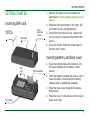
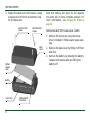
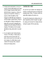
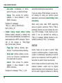
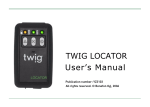
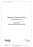
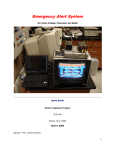
TWIG LOCATOR
User’s Manual
Publication number: YZ3103-03
All rights reserved. © GeoSentric Oyj, 2007
•
This tracking device is designed for use on the E-GSM900/ DCS 1800/ PCS 1900 MHZ Tri Band networks. You can use
the device in all countries where the GSM network operators have a roaming contract with your network operator.
•
The device also includes integrated high-performance 12-channel GPS receiver. The unique combination of GPS and
GSM equipment in this device enables features like tracking and location requests as well as emergency calls and
messages. In order to function properly, some of these features may require third-party services. GeoSentric is not
responsible for such services, their existence, functionality or compatibility with GeoSentric products.
•
Information in this User´s manual is subject to change without notice. GeoSentric reserves the right to change or
improve their products and to make changes in the content without obligation to notify any person or organization of
such changes or improvements. GeoSentric is not responsible for any loss of data, income or any consequential
damage whatsoever caused.
•
Some of the features described in this guide may be optional and intended to be purchased separately. For details,
please contact your dealer.For more information, details and descriptions, including assortment of chargers and
accessories, please visit the web site: www.benefon.com.
•
GeoSentric warrants its products to be free of defects in material or workmanship when leaving the factory. A warranty certificate with the date of purchase is enclosed in the delivery. For details, see the warranty certificate.
Hereby, GeoSentric Oyj declares that this tracking device, type TGP85EG/TGP85NG, is in compliance with the essential requirements and other relevant provisions of Directive 1999/5/EC.
•
FCC warning statements: This device complies with part 15 of the FCC Rules. Operation is subject to following two
conditions: (1) This device may not cause harmful interference, and (2) this device must accept any interference
received, including interference that may cause undesired operation. Changes or modifications not expressly approved by the party responsible for compliance would void the user’s authority to operate the equipment.
•
ACCESSORIES AND BATTERIES: use only accessories and batteries accepted by the product manufacturer. Do not
use incompatibe accessories and batteries.
•
GeoSentric and TWIG are registered trademarks of GeoSentric Oyj.
Manufacturer: GeoSentric Oyj,
P.O. Box 84, 24101 Salo, Finland
Web site: www.benefon.com
0413
Made in Finland.
Copyright © 2007 GeoSentric Oyj. All rights reserved.
Correct disposal of this product:
The tracking device should not be
disposed with household or other
commercial wastes. Remove the
battery from the phone and dispose it according to local battery recycling laws.
CONTENTS
CONTENTS
TWIG LOCATOR . . . . . . . . . . . . . . . . . . . . . . . . . . . . 6
TWIG Locator G Series . . . . . . . . . . . . . . . . . . . . 6
Alarm . . . . . . . . . . . . . . . . . . . . . . . . . . . . . . . . . 15
NMEA output . . . . . . . . . . . . . . . . . . . . . . . . . . . 15
Messaging . . . . . . . . . . . . . . . . . . . . . . . . . . . . . 16
SENDING AND RECEIVING MESSAGES . . . . . . . . 16
GETTING STARTED. . . . . . . . . . . . . . . . . . . . . . . . . 7
VOICE CALLING . . . . . . . . . . . . . . . . . . . . . . . . . . . 17
Inserting SIM-card . . . . . . . . . . . . . . . . . . . . . . . 7
G Series features . . . . . . . . . . . . . . . . . . . . . . . . 17
Inserting battery and back cover . . . . . . . . . . . . 7
TIMER MODE. . . . . . . . . . . . . . . . . . . . . . . . . . . . . . 18
REMOVING BATTERY AND BACK COVER . . . . . . . . 8
CHARGER ON MODE . . . . . . . . . . . . . . . . . . . . . . . 18
KEYS, LEDS AND OUTER PARTS. . . . . . . . . . . . . . 9
G-SENSOR. . . . . . . . . . . . . . . . . . . . . . . . . . . . . . . . 19
MAN DOWN ALERT . . . . . . . . . . . . . . . . . . . . . . . . 19
Turning TWIG Locator on and off . . . . . . . . . . . . 9
STATUS INPUT . . . . . . . . . . . . . . . . . . . . . . . . . . . . 20
Status LEDs . . . . . . . . . . . . . . . . . . . . . . . . . . . . 10
GPS TRACE . . . . . . . . . . . . . . . . . . . . . . . . . . . . . . . 20
Charging the battery . . . . . . . . . . . . . . . . . . . . . 10
CONFIGURATING LOCATOR . . . . . . . . . . . . . . . . 21
CHARGING ONLY MODE . . . . . . . . . . . . . . . . . . . . . 11
Installing software and drivers . . . . . . . . . . . . 21
TWIG LOCATOR FEATURES . . . . . . . . . . . . . . . . . 12
Opening connection . . . . . . . . . . . . . . . . . . . . . . 21
Stand-by mode. . . . . . . . . . . . . . . . . . . . . . . . . . 12
Opening and saving settings. . . . . . . . . . . . . . . 23
Positioning . . . . . . . . . . . . . . . . . . . . . . . . . . . . . 12
Device information . . . . . . . . . . . . . . . . . . . . . . 23
Tracking . . . . . . . . . . . . . . . . . . . . . . . . . . . . . . . 12
Updating software . . . . . . . . . . . . . . . . . . . . . . . 23
Anchor. . . . . . . . . . . . . . . . . . . . . . . . . . . . . . . . . 14
3
CONTENTS
Configuration settings. . . . . . . . . . . . . . . . . . . . 23
CONFIGURATION SETTINGS 1-16 . . . . . . . . . . . . . 24
Config 1: PIN Code . . . . . . . . . . . . . . . . . . . . . . 24
Config 2: ID . . . . . . . . . . . . . . . . . . . . . . . . . . . . 25
Config 3: Security code . . . . . . . . . . . . . . . . . . . 25
Config 4: Translate header . . . . . . . . . . . . . . . . 25
Config 5: Alarm button pressed message . . . . 25
Config 6: SMSC number . . . . . . . . . . . . . . . . . . 26
Config 7: Ext. button status message. . . . . . . . 26
Config 8: Terminate voice call . . . . . . . . . . . . . 26
Config 9: Voice call auto answer . . . . . . . . . . . 26
Config 10: Auto leaving from alarm mode . . . . 27
Config 11: Max GPS search time . . . . . . . . . . . 27
Config 12: GPS update in basic mode . . . . . . . . 27
Config 13: GPS update in Tracking mode . . . . . 28
Config 14: GPS update in Anchor mode . . . . . . 28
Config 15: Max. allowed movement in Anchor mode
. . . . . . . . . . . . . . . . . . . . . . . . . . . . . . . . . . . . . . 28
Config 16: Battery alarm level . . . . . . . . . . . . . 28
CONFIGURATION SETTINGS 17-32 . . . . . . . . . . . . 28
Config 17: !IND messages. . . . . . . . . . . . . . . . . 28
Config 18: Mic Bbcgain . . . . . . . . . . . . . . . . . . . 29
Config 19: Trace log save . . . . . . . . . . . . . . . . . 29
4
Config 23-27: Alarm numbers . . . . . . . . . . . . . 29
Config 28-32: Voice call numbers . . . . . . . . . . 29
CONFIGURATION SETTINGS 33-48 . . . . . . . . . . .
Config 33: On/off timer . . . . . . . . . . . . . . . . . .
Config 34: Startup time . . . . . . . . . . . . . . . . . .
Config 35: Power on interval . . . . . . . . . . . . . .
Config 36: Power off delay . . . . . . . . . . . . . . .
Config 37: Accelometer sensitivity . . . . . . . . .
Config 38: Accelometer duration . . . . . . . . . .
Config 39: Man down mode . . . . . . . . . . . . . . .
Config 40: Man down timers . . . . . . . . . . . . . .
Config 41: Man down alert angle. . . . . . . . . . .
Config 45: Locator hardware version . . . . . . .
Config 46: MC55 HW revision . . . . . . . . . . . . .
Config 47: MC55 IMEI number . . . . . . . . . . . . .
Config 48: Locator II FW revision . . . . . . . . . .
30
30
30
31
31
31
31
31
32
32
33
33
33
33
WHITE LIST NUMBERS . . . . . . . . . . . . . . . . . . . . . 33
White L 1-16 and 17-32 . . . . . . . . . . . . . . . . . . 33
GPRS SETTINGS . . . . . . . . . . . . . . . . . . . . . . . . . . .
User-defined GPRS ID . . . . . . . . . . . . . . . . . . .
APN parts 1-3 . . . . . . . . . . . . . . . . . . . . . . . . .
GPRS IP address . . . . . . . . . . . . . . . . . . . . . . .
GPRS port number . . . . . . . . . . . . . . . . . . . . . .
34
34
34
35
35
CONTENTS
GPRS DNS 1-2 . . . . . . . . . . . . . . . . . . . . . . . . . . 35
GPRS user name . . . . . . . . . . . . . . . . . . . . . . . . 35
GPRS password . . . . . . . . . . . . . . . . . . . . . . . . . 35
GPRS international roaming blocking . . . . . . . 35
Heartbeat interval. . . . . . . . . . . . . . . . . . . . . . . 35
Reconnect interval . . . . . . . . . . . . . . . . . . . . . . 36
ACCESSORIES AND BATTERIES . . . . . . . . . . . . . 36
5
TWIG LOCATOR
TWIG LOCATOR
TWIG Locator G Series
TWIG Locator is an auxiliary device for locating and tracking different targets. Place Locator on your desired target, e.g car, and you
can easily monitor its location.
TWIG Locator G Series includes new and
improved features for e.g accelerator sensor
and using extra memory.
TWIG Locator can send you continuously
updated position messages. With these messages, you can easily track your Locator’s
movements. You can also create an anchor
that alarms you if your Locator is moved outside of your defined area.
You can call and send messages to Locator for
its updated position at any time. Additionally,
by making a voice call, you can also listen to
what happens nearby the device.
TWIG Locator is a GSM-device with in-built
GPS-positioning and support for MPTP commands. It can be used with any corresponding
TWIG/ Benefon GPS-GSM phones and backend devices with support for MPTP commands.
You can purchase MPTP document at GeoSentric salesoffice.
6
The G series represents the following device
variants with customized keys and outer
parts:
Locator G
Locator G SE
Locator G LE
Note that functions, features, and usability
described in this user manual are intented for
using only Locator G Series devices. Some
functions and features may not be available in
previous Locator variants.
GETTING STARTED
1. Remove the back cover and battery as
described in removing battery and back cover on
page 8.
GETTING STARTED
Inserting SIM-card
Short
back side
screws
Long front
side screws
Back cover
2. Slide the SIM card holder to the right. Lift
the holder into an upright position.
3. Insert SIM card into the hole. Check that
the cut corner is placed at the bottom left
corner.
4. Close the holder. Slide the holder back to
the left until it locks.
Inserting battery and back cover
SIMcard
SIM-card holder
1. Place the bottom tabs of the battery into
the small hollows at the bottom of the
device.
2. Push the battery towards the device until it
locks into place. Ensure that the battery
release catch is positioned upwards.
3. Place the back cover towards the device,
bottom first.
Front cover
4. Press the cover to the device until it locks in
place at the top.
7
GETTING STARTED
5. Fasten the back cover with screws. Longer
screws are for the front and shorter ones
for the back side.
Long front side
screws
Short back side
screws
Note that battery will reach its full capacity
only after two or three complete charges. For
more information, see charging the battery on
page 10.
REMOVING BATTERY AND BACK COVER
1. Remove the screws by using the screwdriver included in TWIG Locator sales package.
Back
cover
3. Remove the battery by pressing the battery
release catch downwards and lifting the
battery off.
Battery
release
catch
Battery
Front cover
8
2. Remove the back cover by lifting it off front
side first.
Bottom tabs of
the battery
KEYS, LEDS AND OUTER PARTS
KEYS, LEDS AND OUTER PARTS
GSM LED
Status LED
GPS LED
Anchor
button
Emergency
button
Power on/
off button
Note that available keys may depend on the
Locator version in use.
Turning TWIG Locator on and off
You can turn TWIG Locator on by pressing the
power on/off key. As a sign of starting-up, all
three LED indicators turn on for a couple of
seconds. After that the status LED continues
blinking for about 20 seconds.
To turn the device off, press the power on/off
key again.
Note that turning Locator from power key
stops verticality sensor from operating, as
well as cancels all tasks set for timer. These
operations will be reset automatically when
the device is turned back on.
If you wish to keep timer tasks and verticality
sensor operation active while your device is
powered off, use power off timer to shut down
the device.
Bottom connector for
charger (round hole
on the left)
Bottom connector for USB-cable
9
KEYS, LEDS AND OUTER PARTS
Status LEDs
When TWIG Locator is turned on, LED indicators express the status of the device the following way:
You can ask the battery status by pressing the
power on/off button. The status LED indicates
battery level the following way:
Blinks/sequence
Battery status
LED
Indicator light
1
Low (0-20%)
Status LED
Off, when the device is in
standby-mode.
Continuously on during startup, and when establishing
GPRS connection
2
Fairly low (21-40%)
3
Fairly full (41-60%)
4
Almost full (61-80%)
GSM LED
Continuously on, when data
call is on, or a SMS message
is being sent or received.
Continuously on
Battery full (81-100%)
GSM LED
1 blink/sequence when having a network
GPS LED
1 blink/sequence, if the GPS
has a valid position fix that is
not older than 5 minutes.
GPS LED
Continuously off, if previous
position is older that 5 minutes and a new position fix is
not available.
When battery is low, Locator also sends battery alarm message to your defined destination numbers. For more information, see config
23-27: alarm numbers on page 29.
Charging the battery
1. Plug the charger cable into the bottom connector of the device (round hole on the lefthand side).
2. Plug the charger into the mains outlet.
10
KEYS, LEDS AND OUTER PARTS
3. Charging starts automatically. As a sign of
charging, all three LED indicators are turned
on for a couple of seconds. After that the
GSM LED blinks in sequences, 2 blinks in a
sequence at first and then 4 blinks in a
sequence. When the battery is fully
charged, the GSM LED stays constantly on
until the charger is disconnected. If there is
an interruption or failure in charging, the
status LED is turned off. Unplugging and
replugging the cable displays the status of
charging. If the battery is full, the status
LED blinks 4 times, after which it is turned
off.
CHARGING ONLY MODE
You can turn your Locator into charging only
mode by connecting the device to charger and
pressing power off key. The device cannot be
used when charging only mode is on.
To cancel the charging only mode and turn on
device operations, press the power key again.
Or, unplug and reconnect the charger without
turning the power off from power key.
4. You can operate Locator during charging.
However, if the battery is totally empty, it
might take several minutes before the
device can be used. If you turn Locator on
while charging, the LEDs indicate events
related to the ongoing mode, instead of
showing the charging status.
11
TWIG LOCATOR FEATURES
TWIG LOCATOR FEATURES
Stand-by mode
When TWIG Locator is turned on, it enters
into stand-by mode. In the stand-by mode,
the device is not activated by any process but
it is ready to receive and answer location
requests. Stand-by mode is deactivated when
some other mode is activated.
Positioning
You can ask your Locator’s position by sending
it a ?LOC message. If you are using a TWIGhandset, you can send the message by using
your phone’s special application and choosing
Request position. Or you can send Locator an
SMS message containing the command
?LOC_0.
As a response, you will receive a message
including information on your Locator’s position in coordinates, as well as speed, heading,
battery level and time stamp of the position.
12
Tracking
Tracking mode means that Locator is activated
to continuously send updated location information. In the tracking mode, you can easily
monitor movements of e.g. your car.
Tracking mode can be activated simultaneously with anchor and alarm modes.
Sending tracking and area tracking requests
If you are using Benefon ESC or TWIG Discovery Pro with the required special application
activated, you can activate both tracking and
area tracking features as follows:
Send a tracking request to Locator by choosing the option Request tracking. Area tracking
is activated by selecting Request area tracking.
You can then select On exit if you wish Locator
to alert you when the device is leaving your
defined area. Or you can select While out if you
wish Locator to send you position messages
while staying outside of the defined area. You
can also set radius for the tracked area as well
as interval for tracking updates.
TWIG LOCATOR FEATURES
The other way to activate tracking is by sending Locator a ?TRC (simple tracking request
with interval in minutes), ?TRS (simple tracking request with interval in seconds), or ?TRG
(complex tracking request) message from a
mobile phone or a back-end system supporting MPTP protocol.
• Simple tracking request, interval in minutes
The
format
of
the
request
is:
?TRC_Interval_Number of reports.
- Interval: Time interval for position
updates. A value between 1 and
65535 (minutes).
- Number of reports: Total number of
position updates. A value between 1
and 65535.
Example of a message: ?TRC_10_20
• Simple tracking request, interval in seconds
The
format
of
the
request
is:
?TRS_Interval_Number of reports
- Interval: Time interval for position
updates. A value between 60 and
65535 (seconds).
- Number of reports: Total number of
position updates. A value between 1
and 65535.
Example of a message: ?TRS_60_30
• Complex tracking request, area tracking
The format of the request is: ?TRG_Trigger
type_Service
state_Radius_Method_Area
centre_Interval
- Trigger type: Defines tracking type.
Choose 0 to activate area tracking.
- Service state: Defines whether service
is on or not. Choose 1 to activate and
0 to deactivate the service.
- Radius: Defines radius for the tracked
area. A value between 1 and 9999
(metres).
- Method:
Defines
when
tracking
updates are sent by Locator. Choose 0
if you want to receive tracking
updates while Locator stays outside
the defined area. If you wish Locator
to alert you when the device leaves
the defined area, choose 3.
13
TWIG LOCATOR FEATURES
- Area centre: Coordinates of centre
point of the area, in WGS-84 format.
- Interval: Time interval for position
updates. A value between 1 and
65535 (minutes).
Example of a message:
?TRG_0_1_1000_0_N68.28.43,9_
E027.27.02,4_15
• Complex tracking request, endless tracking
Endless tracking activates a tracking that
does not stop automatically, but needs to be
deactivated with a MPTP command. The format of the request is: ?TRG_Trigger
type_Service state_Interval
- Trigger type: Defines tracking type.
Choose 7 to activate endless tracking.
- Service state: Defines whether service
is on or not. Choose 1 to activate and
0 to deactivate the service.
- Interval: Time interval for position
updates. A value between 1 and
65535 (minutes).
Example of a message: ?TRG_7_1_60
14
Cancelling tracking and area tracking
If you are using a TWIG handset, you can cancel tracking by using your phone’s special
application and choosing Cancel tracking/ Cancel
area tracking.
When using some other MPTP supporting
device or system, and either ?TRS or ?TRC is
activated, tracking can be cancelled by sending a ?STO message. If area tracking is activated, it can be cancelled by sending a
?TRG_0_0 message. Endless tracking is cancelled by sending a ?TRG_7_0 message.
Anchor
Anchor mode can be used to anchor TWIG
Locator to a defined position. In anchor mode,
Locator is continuously calculating its current
position and comparing it with the position it
had when the anchor mode was entered.
Anchor mode is switched to alarm mode, if the
distance between Locator and its original
position becomes more than allowed. You can
set the alarm triggering distance by defining
TWIG LOCATOR FEATURES
maximum allowed movements in configuration settings. For more information, see config
15: max. allowed movement in anchor mode on
page 28.
To enter the anchor mode, press and hold
down anchor button for about 5 seconds. You
can deactivate the mode by pressing the
anchor button again. Anchor mode can be
activated simultaneously with tracking and
alarm modes.
Alarm
Alarm mode is activated, when the alarm button is pressed and held down for 3 seconds. If
there is an external alarm button connected,
it can also be used to activate the alarm
mode. In the anchor mode, the alarm is activated automatically when TWIG Locator is
moved outside the defined area.
In the alarm mode, Locator is running at full
power and is ready to respond to your commands. Pressing the alarm button activates
Locator to send an SMS message and start a
voice call to the numbers you have defined in
configuration settings. See config 23-27: alarm
numbers on page 29 and config 28-32: voice call
numbers on page 29 for more information.
Once the alarm button is pressed and the
voice call is established, the call has an automatic duration of ten (10) minutes, after
which the call is stopped automatically. During
that time no new voice calls can be made
even if the alarm button is pressed again and/
or the established call is stopped manually
before ten minutes is over.
The alarm mode is automatically deactivated
if another mode is activated by a command.
You can also define automatic time-out for the
alarm mode in configuration settings, see config 17: !ind messages on page 28.
NMEA output
TWIG Locator can send position information
also as NMEA strings. NMEA, a GPS-based
data transferring standard, is used to transfer
data from Locator to PC.
15
TWIG LOCATOR FEATURES
NMEA mode can be activated while in any
other mode: tracking mode, anchor mode or
alarm mode. Connect Locator to PC with mini
USB cable. Activate the NMEA mode by pressing and holding down the anchor and alarm
buttons simultaneously for 3 seconds. When
the mode is activated, the sending of NMEA
data is started.
If you want to leave the NMEA mode, press
and hold down the buttons again.
Messaging
SENDING AND RECEIVING MESSAGES
Position updates, tracking updates, anchor
and other alarms are transmitted as SMS
messages or via GPRS, depending on the connection mode defined in configuration settings. See more information on configuring
GPRS connection, in gprs settings on page 34.
Sending tracking updates and anchor alarms,
is automatical when the desired mode is on,
and defined conditions are fulfilled. Messages
are sent to phone numbers defined as your
16
destination numbers. See config 23-27: alarm
numbers on page 29 for more information. If
both SMS messaging and GPRS connection are
in use, messages are sent by using them
both.
You can send an update request to your Locator by using your phone’s special applications,
e.g. TWIG Navigation, or TWIG Web Finder.
When a position update request is received
via SMS, Locator automatically checks if the
sender’s phone number can be found in White
list. Requests received via GPRS are authenticated on the basis of server ID and your own
MSID defined in configuration settings. See
gprs settings on page 34 for more information.
If the sender’s phone number is stored in
White list, or if White list is empty, the phone
number is consired as valid, and position
update is sent as a reply. For more information about White list, see white list numbers on
page 33.
TWIG LOCATOR FEATURES
VOICE CALLING
G Series features
Voice calling enables you to listen to your
Locator. When a call starts, Locator’s microphone is activated and you can listen to what
happens within microphone’s reach e.g. other
person’s speak. Note that there is no speaker
in Locator, so transmitting voices to Locator is
not possible.
Locator G series devices include special features for timing and using accelometer. These
features help you to preset activity of your
device.
A voice call can be initiated by Locator or a
partner. If the call is initiated by Locator, the
available phone numbers are defined in voice
call numbers. See config 28-32: voice call
numbers on page 29 for more information.
If the call is coming from a partner, and automatic answer is set off, the call is automatically rejected. If the automatic answer is set
on, the phone number is automatically compared to the phone numbers stored in White
list. If the number is stored in the list, or if
White list is empty, the call is accepted. For
more information about defining automatic
answer and White list, see config 9: voice call
auto answer on page 26 and white list numbers on
page 33.
Note that to use any timer functions, Locator
device must be turned on from power key and
let to power off automatically using the power
off timer. Turning off by pressing the power
key, cancels all timer functions. In that case,
the timer won’t activate even if configurated
timelines are met. For more information on
power off timer, see config 36: power off delay on
page 31.
Once the device is off, you can turn it normally on by using the power key. Power off
timer will turn it off automatically if the mode
is not changed to another mode e.g. by connecting charger.
17
TWIG LOCATOR FEATURES
TIMER MODE
When timer mode has been activated on your
Locator, the device will turn on at every set
interval. When the device is on, and there are
previously actived processes e.g. tracking,
those will restart automatically. After successfull start-up, the device stays active until the
defined power off delay has passed, and the
device is automatically powered off. For more
information on power off delay, see config 36:
power off delay on page 31.¨
Upgrading software brings the timer mode
available also to Locator devices previous to G
series.
Tracking or other processes are resumed in
Timer modes only via GPRS. SMS-based
trackings are not resumed when powering on
with timers.
If there is need for location updates on SMSbased messaging, the INF messages can be
used when powering on. Or sending LOC when
the device is ON. NOTE messages that are
18
long time in operators SMS-C may not reach
device.
CHARGER ON MODE
When timer mode is activated on your Locator, (config 33: on/off timer on page 30), the
device automatically powers on and restarts
all previously activated processes on the
defined time interval. If there is a charger
connected to the device, it will stay on until
the charger is unplugged. When charger on
mode can no longer be detected, or charging
voltage is cut off, the device will be powered
off again, after the set power off delay (config
36: power off delay on page 31) has passed.
Charger on mode then overrides the timer and
g-sensor modes, and keeps the device on,
until charger is disconnected.
Upgrading software brings the charger mode
available also to Locator devices previous to G
series.
TWIG LOCATOR FEATURES
G-SENSOR
MAN DOWN ALERT
Using G-sensor mode requires that there is
accelerometer in your Locator unit.
The purpose of man down feature is to monitor device orientation, and launch alert if horizontal/vertical orientation is lost.
When timer mode is activate on your Locator
( config 33: on/off timer on page 30), also accelometer is used to start up the device. When the
defined accelometer parametres are met, the
device starts up, and all active processes e.g.
tracking are activated.
When turning on by sensitivity condition, the
condition must be met for the time defined in
accelerometer duration. If the condition
meets the defined time, the device is turned
on. When the device is turned on, it keeps
checking the sensitivity condition. Condition is
monitored continously and every met value
resets the power off timer, and the device
remains activated. For more information, see
config 37: accelometer sensitivity on page 31 and
config 38: accelometer duration on page 31.
- Horizontal orientation: The device is
considered to have horizontal position
when its angle from absolute lateral
orientation (device in absolute horizontal position, LED lights facing up )
differs less than than the defined man
down alert angle. The difference is
measured in degrees.
- Vertical orientation: The device is
considered to have vertical orientation when its angle from absolute
upright orientation (device in absolute vertical position, connectors facing down) differs less than the
defined man down alert angle. The
difference is measured in degrees.
Man down angle is defined in configuration
settings. See config 41: man down alert angle on
page 32 for more information.
19
TWIG LOCATOR FEATURES
You can select whether vertical or horizontal
orientation is used as a basis to which
changes in device orientation are compared.
To prevent false alarms, there is a short, configurable time delay between detected orientation shift and launching alert. During this
time the device waits for the original orientation to be restored. If this happens, alert is
not activated.
Note that man down alert feature is not in
use, when Locator is connected to charger.
STATUS INPUT
Status input feature converts external alarm
or anchor alert button, or both of them to
send ?STA message to the number defined in
Alarm number 1 field in configuration settings. Note that any other function cannot be
active at the same time with status input.
For more information on defining status input,
see config 7: ext. button status message on page 26.
20
GPS TRACE
You can store your Locator’s GPS position
information. The trace can include up to 10
000 locations, which can be read in L2U.log
file.
For more information on storing GPS trace,
seeconfig 19: trace log save on page 29.
CONFIGURATING LOCATOR
CONFIGURATING LOCATOR
Installing software and drivers
You can find Locator software and necessary
drivers in the CD-ROM included in your TWIG
Locator sales package. Latest drivers and configuring tools are available under support section in www.twigworld.com.
Connect Locator to your computer with Miini
USB cable. The operating system will notify
you of finding new device, and prompt for
installing necessary drivers. Select to install
drivers manually, and then browse for drivers
in the CD-ROM directory, or your local folder if
you downloaded the drivers from support web
site.
Note that since Locator uses two ports, the
system will prompt for drivers twice. When
this happens, repeat the manual installation
of drivers. After the installation is done, you
may need to restart and reconnect Locator
before changes take effect.
To install Locator configuration software,
select the software file (.exe) from the CDROM and save it in your computer. The configuration software is ready to be used without
separate installation.
Opening connection
Once the software and drivers are installed,
you can establish a connection between Locator and your computer.
Note that Locator must be turned off when
connecting to computer except when the
NMEA mode is activated.
Connect Locator to your computer with Mini
USB cable. Then open the configuration software by double-clicking Locator .exe-file, or,
depending on the version, L2UPDATE.EXE, on
your computer.
Locator connects automatically to the right
COM port, which you can see in COM dropdown menu. If connection is not created automatically, you can also choose the right COMport manually from the COM drag-down menu
21
CONFIGURATING LOCATOR
Opens configuration
settings 17-32
Opens configuration settings 33-48
Opens White list 1-16 and 17-42
Opens GPRS settings
Opens configuration settings 1-16
Restore default
settings
Read GPS trace log
Connect to COM port
Select COM port
Configurate
Locator
Browse to select
configuration file
Read settings
from Locator
Save settings to PC
Browse to select
software update file
Update software
22
Read settings from PC
CONFIGURATING LOCATOR
and press Connect. The connection between
Locator and PC is established, and existing
Locator settings are displayed in configuration
settings fields.
save the configuration settings to your PC,
press File Write EE.
Opening and saving settings
The Info box displays details on your Locator ,
including the IMEI (International Mobile
Equipment Identity) code as well as software
version and GSM module numbers.
Before opening and saving configuration settings, make sure that the connection between
TWIG Locator and the PC is established in a
way described in opening connection on page 21.
To open existing configuration settings for
editing and saving, press the Select EE button
to search for your TWIG Locator configuration
file. Then press Read EE to open the settings
which are currently saved in Locator. If you
wish to open the settings file stored on your
computer, press File Read EE. You can now edit
the settings as you wish.
You can configurate your Locator according to
your defined settings by pressing the Program
EE button. A progress bar displays the status
of the configuration update. If you want to
Device information
Updating software
Updating software is done in the Firmware
field. Press Select FW to browse for the software update file. Update your existing TWIG
Locator software by pressing Program FW. A
progress bar displays the status of the updating process.
Configuration settings
You can open Locator configurator settings
from the top tab row of Locator software.
Click the desired tab, and the available settings will open in the software main view.
23
CONFIGURATING LOCATOR
Note that Locator settings are case sensitive.
If available values are YES/ NO, the chosen
setting must be written with uppercase letters. If there are wrong characters, or other
invalid values set in the configuration field,
those are ignored and default value is taken
into use.
You can also restore default settings to your
device by pressing Set defaults.
CONFIGURATION SETTINGS 1-16
Connect Locator to your computer as
described in opening connection on page 21. You
can edit and define several settings, including
security settings and available connections, to
be used with your Locator.
Config 1: PIN Code
PIN code (4 digits) is used to unlock Locator’s
SIM card, unless you are using a SIM card in
which the PIN code is disabled.
Default value for PIN code is 0000. Replace the
value with your own PIN code, or leave the
field blank if the PIN code has been disabled.
24
If
the
PIN
code
is
defined incorrectly,
you
won’t be able
to
turn
on
your Locator.
After
three
failured
attempts, the
SIM card will
be blocked.
If your SIM
card
gets
blocked, you need a PUK code (8 digits) to
open it. Remove the SIM card for Locator and
install it into a phone compatible with your
SIM card. When trying to open the phone, it
will prompt you for the PUK code. After entering the PUK code, key in a new PIN code. You
can then install the SIM card back to Locator.
If you fail to key in the correct PUK code 10
times in a row, your SIM card will be permanently blocked. If this happens, contact your network operator to get a new SIM card.
CONFIGURATING LOCATOR
Config 2: ID
You can define an identification for your Locator. This code may contain both numbers and
letters, and it is case sensitive. Default value
for the ID code is: Locator.
Config 3: Security code
Security code is used when configurating
Locator and activating its different features.
The security code consists of 4 digits. Default
security code is 0000.
Config 4: Translate header
Translate header defines whether special
characters in the beginning of SMS based
MPTP messages are replaced by letters or not.
The replacement is necessary with some
mobile phone operator systems (e.g. Russian
and China). If Translate header is set to
• YES: The question mark (?) in the beginning
of MPTP requests is replaced by the letter Q.
The exclamation mark (!) in the beginning of
MPTP updates and replies is replaced by the
letter E.
• NO: Selecting NO restores the original settings for MPTP messages. Question mark (?)
is used in the beginning of requests, and
exclamation mark (!) is used as the start
character for replies and updates.
Default value for Translate header is NO. If the
field is left blank, the default value is taken
into use.
Note that to use Locator with TWIG Discovery
Pro, or some other back-end devices, you
need to make sure that Translate header is
configured correspondingly also in the other
device. If MPTP message start character is
configured differently in the other device,
sending and receiving MPTP messages from
Locator is not possible.
Config 5: Alarm button pressed message
You can create a short message to be included
in MPTP messages sent when Locator’s alarm
button is pressed.
The maximum lenght of this message is 16
characters. Default message is Alarm button
pressed.
25
CONFIGURATING LOCATOR
Config 6: SMSC number
Config 8: Terminate voice call
SMCS number defines the SMS center number
used in SMS messaging. If no SMS center
number is defined in this setting, Locator
automatically reads the number in your SIM
card.
Voice calls can be initiated by Locator under
specific circumstances. Terminate voice call
defines time limit for those voice calls which
automatically answered by Locator. When the
limit is reached, the voice call will be closed
automatically. Available values for the time
limit are: 00.01.00... 00.59.00 (hh.mm.ss).
Default value is 00.10.00 (ten minutes).
If you wish to define a number in the SMSC
number field, write the digits together without
blanks and special characters. If you wish to
use international phone numbers, write sign +
and the country code in front of the number.
Or use national phone numbers without + and
the country code.
Note that Terminate voice call settings are taken
into use only if automatic voice call answering
is set to YES. For more information, see config
9: voice call auto answer on page 26.
Config 7: Ext. button status message
Config 9: Voice call auto answer
Defines whether status input is in use or not.
Set the value as following:
You can define whether or not you wish Locator to answer automatically to incoming voice
calls. Default value for this field is NO. If you
wish to set the automatic answer on, type
YES.
0 (zero) = No status input
1 = Turns alarm into STA1 message.
2 = Turns anchor alert into STA2 message.
3 = Alarm is turned into STA1 message and
anchor alert into STA2 message.
26
Answering voice calls depends on both the
automatic answer and White list settings:
CONFIGURATING LOCATOR
• Automatic answer is off, there are no numbers stored in White list: Incoming call is
rejected.
• Automatic answer is off, there are numbers
stored in White list: If the caller’s phone
number can be found in the White list, the
call is not answered but a location (!LOC)
message is sent to the caller. If the caller’s
number cannot be found in the list, the call
is rejected without sending location message.
• Automatic answer is on, there are no numbers stored in White list: All incoming calls
will be answered.
• Automatic answer is on, there are some
numbers stored in White list: If the caller’s
number can be found in White list, the call is
answered. Otherwise the call is rejected
without sending a location message.
For more information about White list numbers, see white list numbers on page 33.
Config 10: Auto leaving from alarm mode
Auto leaving from alarm mode defines time
after which Locator automatically leaves the
alarm mode. When the time is full, alarm
mode is terminated, including possible ongoing alarm calls.
Valid values for this field are between 00.30.00
(hh.mm.ss) and 23.59.59 (hh.mm.ss). Default
value is 01.00.00 (one hour).
Config 11: Max GPS search time
You can define for how long GPS is trying to
get a refreshed position after receiving a position request. If the refreshed position is not
acquired within that time, Locator sends position update using the previously stored position. Valid values for GPS search time are
between: 00.02.00... 00.10.59 (hh.mm.ss).
Default value is 00.05.00 (five minutes).
Config 12: GPS update in basic mode
You can define how frequently GPS is updating
position while in basic mode. Time interval
27
CONFIGURATING LOCATOR
can be set to: 00.00.10... 00.59.59 (hh.mm.ss).
Default value is 00.30.00 (thirty minutes).
Config 13: GPS update in Tracking mode
You can define time interval for GPS position
updates in the tracking mode. Valid values are
between: 00.00.10... 00.59.59 (hh.mm.ss).
Default value is 00.10.00 (ten minutes).
Config 14: GPS update in Anchor mode
You can define time interval for GPS position
updates in the anchor mode between:
00.00.10... 00.59.59 (hh.mm.ss). Default value
is 00.01.00 (one minute).
Config 15: Max. allowed movement in Anchor
mode
You can define a maximum distance that
Locator is allowed to move from the original
position in the anchor mode. Once the limit is
exceeded, a movement alarm is triggered.
Allowed distance can be set to: 0100... 9999
meters. Default value is 0300 (300 meters).
28
Config 16: Battery alarm level
Locator can alert you when its battery level is
declined under certain level. You can define
the alarm level at 20, 40, or 60 percentage of
full battery charge. Default value for the
alarm is 20 percent. If the value is set to 00, it
means that the alarm is deactivated.
Note, that battery levels can vary substantially when using Timer modes with long OFF
periods. This may cause wrong or repeating
Low battery alarms.
CONFIGURATION SETTINGS 17-32
Config 17: !IND messages
You can define whether !IND messages can be
sent or not. A !IND message is sent when
anchor alarm is activated by pressing the
anchor button.
The default value for !IND messages is NO. If
you wish to enable sending !IND messages,
change the setting into YES.
CONFIGURATING LOCATOR
Config 18: Mic
Bbcgain
You can define
Locator’s
microphone
volume level.
The field value
can be set to 07,
in
which
each
number
represents an
increase of 6
decibels.
Default value for this field is 6.
Config 19: Trace log save
You can define a minimum distance which
Locator’s GPS position has to change to save
the new position in trace log. The distance can
be set between 0 and 99 999 meters.
Locator trace log can contain up to 10 000
stored positions.
You can read the device log by connecting
your device to PC and pressing Read trace.
Note that the device needs to be turned on
when creating the connection.
Config 23-27: Alarm numbers
You can define five destination numbers in
configuration fields 23-27. Alarm messages as
well as emergency messages are sent to these
numbers. Battery alarm messages (!IND and
!INF messages) are sent only to the number
defined in Alarm number 1.
Write the phone numbers using international
code.
Note that, Locator sends all alarms also via
GPRS connection, if GPRS has been taken into
use.
Config 28-32: Voice call numbers
Available phone numbers for outgoing voice
calls can be defined in configuration fields 2832.
Write the phone number digits together without blanks and special characters. If you want
29
CONFIGURATING LOCATOR
to use international phone numbers, write the
plus sign (+) and a country code in front of
the number. Or use national phone numbers
without the plus (+) and the country code.
When a call is initiated, Locator starts calling
to the first defined phone number (Field 28).
If the call can be established to this number,
there will be no attempts to another numbers.
If the call cannot be established to the first
number, the second number is called instead.
The cycle will go on until one of the phone
numbers answer the call.
Note that outgoing voice calls can be initiated
only if there is at least one voice call number
defined.
CONFIGURATION SETTINGS 33-48
Config 33: On/off timer
On/off timer defines whether timer, charger
timer, or accelerator sensor are activated in
your Locator or not.
On/ off timer value can be set to:
• 0 (zero): Timers are not in use.
30
• 1: Timer mode is activated.
Note that turning Locator off by power key,
dismisses all timers even when on/ off timer is
set on.
Config 34: Startup time
If timer is set on, startup time defines the
first activation time to be used. Define the
value in the format yymmdd hhmmss, UTC
time. If the set value is invalid, it is considered as 0 (zero), and automatically set to current time (the
time on which
Locator
is
turned on for
the first time
after this setting is saved)
+ the defined
power
on
interval.
Define
the
start-up time
CONFIGURATING LOCATOR
in yymmdd
120000.
hhmmss
format,
e.g.
080101
Config 35: Power on interval
When timer is set on, power on interval
defines the time interval at which Locator is
subsequently turned on.
The power on interval can be set between
00.00.00 (hh.mm.ss) and 99.59.59 (hh.mm.ss).
Default value is 00.00.00 which means that the
interval is not in use.
Config 36: Power off delay
When Locator is powered on by power key,
timer, acceleratation sensor, or connecting
charger, power off delay defines the time after
which Locator is automatically shut down.
The power off delay can be set between
00.02.00 (hh.mm.ss) and 11.59.59 (hh.mm.ss).
Default value is 00.05.00 (five minutes).
Config 37: Accelometer sensitivity
mat. The value can be set to 0-10. Note that
when the value is set to 0 (zero), the accelometer is off.
Exceeding the allowed acceleration sends an
!INF message to the number defined in Alarm
number 1 field in configuration settings.
Config 38: Accelometer duration
Defines the time for how long motion needs to
endure, to power Locator on. The value can be
set to 1-250 seconds. Default value is 3 seconds.
If motion stops before Locator is powered on,
the accelometer duration is reset. if motion is
starts again, counting duration starts from the
beginning.
Config 39: Man down mode
Defines man down alert mode. Set the value
as following:
0 = Launches man down alert when horizontal condition is met.
This setting defines the allowed acceleration
when Locator is powered on, in 10*mG for31
CONFIGURATING LOCATOR
1 = Launches man down alert when vertical
condition is met.
2 = Launches alert if detected movement is
less than defined in configuration settings.
37 for a longer period than defined in configuration settings 40 (no-alarm duration
and pre-alarm duration combined).
Config 40: Man down timers
This setting defines timers to be used with
man down alert. Define the desired values for
each timer, separated by comma (e.g.
3,20000,10). Note that the maximum amount
of characters in the field is 16.
• No alarm duration: When an alarm-triggering
orientation (vertical/horizontal by definition) has been detected, device enters to a
no alarm period during which it waits for
normal orientation to be restored, before
actually triggering the alarm. This is useful
to prevent unnecessary alarms e.g. in case
the user has fallen down but is able to get
up quickly. No alarm period can be set to 365535 seconds.
32
• Pre-alarm duration: When an alarm-triggering
orientation has been detected, and the no
alarm period has passed, device enters into
pre-alarm period. During this state the user
is alarmed by vibration, activating in 1-2
second periods. When pre-alarm period is
over, and normal orientation is not restored,
man down alert is launched. Pre-alarm
period can be set to 3-65535 seconds.
• Normal status delay: Normal status delay
defines a period for which the device needs
to be back in normal orientation, before
restoring normal status. The normal status
delay period is useful to prevent restoring
the normal status and cancelling man down
alert by accident. Normal status delay can
be set 1-65535 seconds.
Config 41: Man down alert angle
Defines the value for angle to be used if man
down alert mode is defined in config 39: man
down mode on page 31.
CONFIGURATING LOCATOR
Config 45: Locator hardware version
This field shows hardware version of your
Locator device:
0 = Device is equipped with basic memory.
1 = Device is equipped with extra memory.
2= Device is equipped with accelerometer.
3 = Device is equipped with both extra
memory and accelerometer.
The field is read-only.
Config 46: MC55 HW revision
The hardware version of your device. The field
is read-only.
Config 47: MC55 IMEI number
The IMEI number of your device. The field is
read-only.
Config 48: Locator II FW revision
The software version of your device. The field
is read-only.
WHITE LIST NUMBERS
In the White
list, you can
restrict phone
numbers from
which
voice
calls and commands can be
received
by
your Locator.
White L 1-16
and 17-32
You can define
up to 32 White
list numbers which can be any valid phone
numbers. When there is at least one stored
phone number, White list is activated.
Activated White list means that incoming
voice calls and commands are accepted only,
if they are received from the numbers in
White list. The authorization is done by comparing the last 7 digits of the sender’s phone
number to the corresponding digits of all your
33
CONFIGURATING LOCATOR
stored White list numbers. Note that White list
is activated also, if there are some other characters than phone numbers stored in the
phone number fields.
GPRS SETTINGS
Write the phone number digits together without blanks and special characters. If you want
to use international phone numbers, write the
plus sign (+) in and a country code in front of
the number. Or use national phone numbers
without the plus sign (+) and the country
code.
User ID is a
number used
in identifying
your phone in
server.
Usually this is the
phone
number that your
Locator
device
is
using.
If there are no White list numbers defined,
incoming voice calls and commands may be
accepted from any sending device. For more
information on accepting incoming voice calls,
see config 9: voice call auto answer on page 26.
User-defined
GPRS ID
To use TWIG
Web Finder service with your Locator, make
sure that Locator is configured with the same
phone number as you have defined in Web
Finder.
APN parts 1-3
The access point name used for GPRS communication.
34
CONFIGURATING LOCATOR
Define the entire APN value in the field APN
part 1. If the defined value exceeds 16 characters, it will be automatically cut and continued in the field APN part 2, and if exceeded
again, in the field APN part 3. The maximum
APN value is 48 characters, in all fields
together.
GPRS IP address
Key in the IP address that is used in GPRS
communication. As default, TWIG Web Finder
IP address 192.83.5.99 is used.
GPRS port number
A port number is required for GPRS communication. The value can be set between 0...
65535. As default, TWIG Web Finder service
port 8484 is used.
GPRS DNS 1-2
Some GPRS networks require that primary
domain name server (DNS1) is specified.
Define the DNS as an IP address. Maximum
length for DNS1 name is 16 characters.
Default value for DNS1 is 127.0.0.1 and for
DNS2 127.0.0.2 (TWIG Web Finder).
GPRS user name
If the GPRS network in use requires a user
name for GPRS log-in, define the name here.
GPRS password
If the GPRS network in use requires a password for GPRS log-in, define the word here.
GPRS international roaming blocking
If international roaming block is set to YES,
GPRS connection cannot be used during international roaming. If the value is set to NO,
GPRS connection is available also during
international roaming.
Default value for international roaming blocking is NO. The value is checked every time
when creating GPRS connection.
Heartbeat interval
Heartbeat messages are in use when your
device is connected to charger and connection
35
ACCESSORIES AND BATTERIES
to server is available. Heartbeat messages are
used by the device to keep in touch with the
server. You can set the sending interval for
heartbeat
messages
between
00.01.00
(hh.mm.ss) and 00.30.00 (hh.mm.ss). Default
value is 00.10.00 (ten minutes).
ACCESSORIES AND BATTERIES
Following accessories are available for this
product:
Accessory
Type
Order code
Note that if the value is set to 0 (zero), heartbeat is not in use.
Mains charger
EU
CMA-80-230
YO3005
Reconnect interval
Mains charger
UK
CMA-80-230
YO3006
Plug-in charger
CCS-80-12
YO3010
Stardard battery
BBL-80N
YO3000
Reconnection messages are in use when your
device is not connected to charger. The device
sends reconnection messages to server to
check the server status and incoming messages possibly pending in server. You can set
the sending interval for heartbeat messages
between 00.02.00 (hh.mm.ss) and 23.59.59
(hh.mm.ss). Default value is 00.30.00 (thirty
minutes).
Note that if the value is set to 0 (zero), reconnection interval is not in use.
Mini USB Cable
YC3003
Power supply
cable
YO3171
Note: use only accessories and batteries
approved for this device by the device manufacturer. The use of incompatible accessories and
batteries may cause undesired operation and
void the manufacturer’s warranty for the product. Check the compatibility of new power
supply units and other accessories at the
dealer or manufacturer.
36