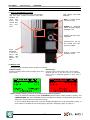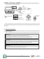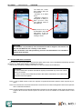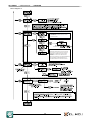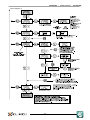
1
VILLEGGIO® USER MANUAL 090060699 Hybrid Multifunctional Control Units for Intrusion Detection Systems VILLEGGIO - USER MANUAL - 090060699 FOREWORD FOR INSTALLERS Please follow carefully the specifications about electric and security systems realization further to the manufacturer’s prescriptions indicated in the manual provided. Provide the user the necessary indication for use and system’s limitations, specifying that there exist precise specifications and different safety performance levels that should be proportioned to the user needs. Have the user read carefully the instructions provided in this document. FOR USERS Carefully check the system functionality at regular intervals making sure all enabling and disabling operations were made correctly. Have skilled personnel make the periodic system’s maintenance. Contact the installer to verify correct system operation in case its conditions have changed (e.g.: variations in the areas to protect due to extension, change of the access modes, etc.) ...................................................... This device has been designed, assembled and tested with the maximum care, adopting control procedures in accordance with the laws in force. The full correspondence to the functional characteristics is given exclusively when it is used for the purpose it was projected for, which is as follows: Hybrid Multifunctional Control Units for Intrusion Detection Systems Any use other than the one mentioned above has not been forecasted and therefore it is not possible to guarantee the correct functioning of the device. Similarly, any other use of this technical manual other than the one it has been compiled for - that is: to illustrate the devices technical features and operating mode - is expressly prohibited. The manufacturing process is carefully controlled in order to prevent defaults and bad functioning. Nevertheless, an extremely low percentage of the components used is subjected to faults just as any other electronic or mechanic product. As this item is meant to protect both property and people, we invite the user to proportion the level of protection that the system offers to the actual risk (also taking into account the possibility that the system was operated in a degraded manner because of faults and the like), as well reminding that there are precise laws for the design and assemblage of the systems destinated to these kind of applications. The system’s operator is hereby advised to see regularly to the periodic maintenance of the system, at least in accordance with the provisions of current legislation, as well as to carry out checks on the correct running of said system on as regular a basis as the risk involved requires, with particular reference to the control unit, sensors, sounders, dialler(s) and any other device connected. The user must let the installer know how well the system seems to be operating, based on the results of periodic checks, without delay. Design, installation and servicing of systems which include this product, should be made by skilled staff with the necessary knowledge to operate in safe conditions in order to prevent accidents. These systems’ installation must be made in accordance with the laws in force. Some equipment’s inner parts are connected to electric main and therefore electrocution may occur if servicing was made before switching off the main and emergency power. Some products incorporate rechargeable or non rechargeable batteries as emergency power supply. Their wrong connection may damage the product, properties and the operator’s safety (burst and fire). YOUR DEALER: 2 090060699 - USER MANUAL - VILLEGGIO 1. GENERALS VILLEGGIO is a microprocessor-based control unit designed to realize high-performance intrusion detection systems with the following special features (according to the model in use): • • • • • • • • • • • • • • • • • Advanced electronic components and circuits. Advanced design. Low-profile plastic housing with the possibility of flush mount. Possibility to install VILLEGGIO on to walls or brickwalls using the optional accessory IBOX. Optional side flanges available in various colours for a stylish personalization. Optional plug-in modules to increase VILLEGGIO operating functions. Built-in chrothermostat with boiler failure detection and SMS-based remote control. Two different models available, VIBASIC and VIDOMO, to meet all onfiguration and performance level requirements. Expansion wired/wireless modules to increase VILLEGGIO operating capacity. Support of control devices connected over RS485 serial line (VIDOMO.) Expandable with concentrators connected over RS485 serial line (VIDOMO.) Exceptional flexibility when configured from a PC. Operating flexibility with remote commands. Suitable for mobile applications (camper vans, watercrafts, etc.) Suitable for standard (i.e. non-mobile) applications (houses, offices, etc.) Considerable energy saving due to the extremely low mains and battery consumption. Compliant with EN50131 standard. • VILLEGGIO is an EL.MO. S.p.a. registered trademark. NOTE: in this manual AREA stands for ’a group of sectors’ and SECTOR (also PARTITION) stands for ’a group of detectors/zones’. 2. BLOCK DIAGRAMS OF VILLEGGIO SYSTEM Operating diagram: 3 VILLEGGIO - USER MANUAL - 090060699 VIDOMO operating diagram: UP TO 64 WIRED / WIRELESS ZONES 8/16 WIRED ZONES ONBOARD VIBASIC operating diagram: 48 TO 64 WIRELESS ZONES ACCORDING TO THE AMOUNT OF WIRED ZONES SET 8/16 WIRED ZONES ONBOARD 4 AM M D EREN A ED R s TYROS MEDICAL REMOTE CONTROL VILLEGGIO SERIES UNITS 5 C-NO-NC RELAY OUTPUT FOR INTRUSION ALARM. UP TO 16 Z ONES WITH SPLIT AND EXTENDED SPLIT FUNCTIONS. TERMINAL BOARD F OR 8 WIRED ZONES CONF IGURATION OPTIONS: DOUBLE BALANCED, TR IPLE BALANCED. NO, NC, FAST. MINIDIN AND MINIUSB CONNECTORS FOR SETUP FROM PC AND FIRMWARE UPDATE PH ONE LINE FOR - DIGITAL DATA TRANSMISSIONS - VOICE DATA TRANSMISS IONS WITH V OICE SYNTHESIS - REMOTE ASS ISTANCE MODELS VIBASIC AND VIDOMO FW. 4.x OR ABOVE 090060699 - USER MANUAL - VILLEGGIO Operating diagram with wireless devices: VILLEGGIO - USER MANUAL - 090060699 3. USER INTERFACE 3.1 View of VILLEGGIO front panel Area with tiny holes for built-in siren sound output. This area also contains microphone and loudspeaker for voice synthesis and remote listening functions. LCD Display with RGB backlight. RED -> armed status and user activity. GREEN -> disarmed status. Normally display backlight is off. System and alarm LED indicators. Sector keys S1, S2, S3, S4. Central area with proxy key reader. Panel case side flange. It can be replaced with others with different colours. Rubber keypad protection cover. with 3.2 Display LCD Backlight status; automatic switch off after one minute. GREEN backlight. Standard operating status before the display turns off for power saving. RED backlight. Exit time mode or armed panel / areas / sectors status. Backlight will turn on also when user is not operating, during codes or commands digitation or when using a proxy key. Note: backlight operating mode can be modified using software application. Users can select two operating modes: STANDARD (as seen above, switch off after 1 minute), and USER-DEFINED, with colours defined by users via software for activity / inactivity status (for inactivity status set a very low light level for power saving.) In case of mains failure while user is inactive, display backlight turns off to save battery charge. In some cases it is possible to use the emergency light (see “Emergency light” on page 37.) 6 090060699 - USER MANUAL - VILLEGGIO 3.3 Panel display standard information POWER SUPPLY NOTE: by default the temperature detected by the module will be displayed on the right and the one detected by the internal sensor on the left. Such positions can be inverted via software. GPS PSTN GSM SIGNAL RF SIGNAL RECEIVED WEEK DAY DATE TEMPERATURE DETECTED HOURS AND MINUTES THE TWO VALUES WILL BE DISPLAYED WHEN OPTIONAL MODULE MDTEMP IS INSTALLED WELCOME MESSAGE BRAND TEMPERATURE DETECTED BY MDTEMP OPERATING STATUS MODEL TEMPERATURE DETECTED BY UNIT BUILT-IN SENSOR The top row of the display, the "icons area" shows the following indications: - The indication of the RF signal will be showed only in case of a valid transmission. Normally, the signal intensity, indicated by bars, will not be showed. According to their number, bars indicate signal level: One bar = poor Two bars = weak Three bars = good Four bars = excellent RF signals are generated by wireless devices of HELIOS series (and compatible.) The indication may refer to other devices operating over the same frequency but not registered. - The indication of power supply status refers to the presence of power supply unit; next to the battery icon, "OK" indicates that there are no anomalies, while a blinking "NO" indicates that there are power anomalies. - Icon with the circled plus (+) sign will be displayed only with GPS module installed; next to the "+" icon, "OK" indicates no anomalies, while a blinking "NO" indicates that there are GPS anomalies. - Telephone icon will be displayed only with PSTN interface module installed; next to the icon, "OK" indicates no anomalies, while a blinking "NO" indicates that there are PSTN anomalies. - Antenna icon will be displayed only with GSM module installed and properly register to the mobile network. Bars next to the icon indicate the level of GSM signal received. When the bars are not visible, it means that there are no registered GSM modules. The display also shows the temperature detected; such indication will blink when the temperature has to be calibrated. Calibration can be performed using both user and installer menus. For calibration procedure, see relevant chapter. The drawing above illustrates the use of the optional remote temperature module MDTEMP. The module can be installed wherever necessary. The display of the temperature detected by the panel built-in sensor can be set as primary or secondary as to the one detected by the radio sensor; the position of the two values on the display can be changed, as well illustrated above. In ordert to avoid confusion, the temperature detected by the panel built-in sensor can be hidden using the panel software. Information about week days, date, and time can be set using both user and installer menus. The display also indicates panel different operating modes by changing backlight colour. According to EN50131 standard, such indications can be hidden (for further information, please see relevant chapter.) Display welcome message can be defined via software application. By default the field shows no messages. 7 VILLEGGIO - USER MANUAL - 090060699 3.4 Information displayed with active chronothermostat VILLEGGIO panel allows to control boiler operating mode; its chronothermostat function can work on daily or weekly schedules and is able to detect boiler failures. If a GSM module has been installed (MDGSMI or MDSGME, optional) it will be possible to send and receive control SMS texts. BOILER ON BLINKING IF BOILER IS BLOCKED TEMPERATURE DETECTED 1 THE DOUBLE DISPLAY REFERS TO THE INSTALLATION OF MDTEMP OPTIONAL MODULE TEMPERATURE DETECTED BY MDTEMP TEMPERATURE DETECTED BY PANEL BUILT-IN SENSOR 2 TEMPORARY TEMPERATURE CHANGE ( = INCREASE = DECREASE) TIME SCHEDULES Note: unit’s display shows 24-hour time schedule for the three temperature time intervals / levels: -->> level 1 (F1) indicates the highest temperature, level 3 (F3) the lowest. Small squares indicate level 1 or level 2; lines indicate level 3. ’Antifreeze level’ is not displayed. Note: The drawing above illustrates the use of the optional remote temperature module MDTEMP. The module can be installed wherever necessary. In order to avoid confusion, the temperature detected by the panel built-in sensor can be hidden using the panel software. Note: The display of the temperature detected by the panel built-in sensor can be set as primary or secondary as to the one detected by the radio sensor; the position of the two values on the display can be changed, as illustrated above. For operating details, please see “Chronothermostat function” on page 32. 8 090060699 - USER MANUAL - VILLEGGIO 3.5 Panel status icons GREEN YELLOW = RED Indicates panel arming condition: ON = No zones in alarm and/or tamper condition. OFF = Alarmed zone(s) not belonging to the exit path. SLOW Blinking = Exit path zones in anomaly condition with disarmed panel OR zone(s) in alarm/ tamper condition generating events different from ’intrusion alarms’. = Indicates panel operating status: ON = Normal operating status. please see note below. SLOW Blinking = System anomaly (Mains failure, Discharged battery, Open tamper contact, or anomaly memories, Fault, RF Anomaly, etc.), zones anomaly. Note: when properly programmed via software, LED indicator will remain OFF when there are no anomalies (System Options > Power Saving > Yellow LED off when there are no anomalies menu.) = General alarm memory: OFF = No active alarms. ON = Intrusion alarm cycle (Relay enabled.) SLOW Blinking = Presence of intrusion memories. = Tamper memories: OFF = No zones in tamper condition. ON = Tamper alarms cycle active (Relay enabled.) SLOW Blinking = Tamper alarm(s) logged. FAST Blinking (for all four indicators) = during configuration from keypad. 3.6 ’S’ keys function Sector keys S1, S2, S3, S4 are used to arm/disarm corresponding sector(s); during configuration procedure keypad backlight remains ON. ’S’ keys backlight ON indicates that the corresponding sector is armed; backlight OFF indicates that the sector is disarmed. ’S’ keys blink slowly during exit time, quickly in case of Max Security arming. 9 VILLEGGIO - USER MANUAL - 090060699 3.7 Keypad operating mode * STOP, , , , and - to display anomalies; - to browse menus; - to select / deselect items; - to save selections made; - to exit panel menus. # OK keys are used: 0 and 1 keys have also an alphabetic function during panel configuration. IMPORTANT: if you press * and # keys simultaneously, this will generate a "Panic alarm" event indicating also the keypad that detected such event. 3.8 Information on the display Press and keys to enter the control menu for: - system anomalies status, - zones anomaly status, - alarm memories, - tamper memories. Arrow keys allow to browse menus; to enter menus press OK key, in case of multiple anomalies use and keys to browse messages to display. To exit menus, use STOP key. Zones not in idle status will be displayed and identified with the name assigned during panel configuration (ex. Kitchen window, hall IR, etc.) Panel operating status will be indicated by the icons: , , , . Normal operating mode will be resumed after one minute from last key pressed. Note: when the ’visualization protection’ function is active (EN 50131 compliance) and has been enabled via software application, the menus cannot be browsed directly with and keys: in such case, the authentication as USER is required by digiting the 6-digit user code and then the arrow keys, or . Information provided refers only to pertaining area. IMPORTANT VILLEGGIO panel can be configured according to EN50131 standard or according to CEI 79-2 standard and the operating indications will be displayed accordingly. This manual will illustrate the two procedures separately. When the panel is armed after a configuration based on EN50131 standard with the ’visualization protection’ function active, system and alarm LED indicators on the front cover and ’icons row’ on the panel display will remain off. Only sector keys (S1, S2, etc.) and remote readers relevant LED will be on according to system status. Readers indication can be disabled via software (System Options > Power Saving > Reader arming LED OFF when inactive menu): reader LED will switch off after one minute from the last command received together with LCD display backlight. 10 090060699 - USER MANUAL - VILLEGGIO In case of GPS module installation, its operating status can be controlled via the system menu on "GPS Status" page from the panel keypad. Example: The distance value can be hidden bye the installer via panel software. 3.9 Acoustic signals for zones anomaly condition (Din-don) For special requirements, the panel can be set to emit a single or continuous beep sound when one or more zone(s) enter(s) an anomaly condition. 4. OPERATING MODE Note: VIDOMO unit can be connected to remote control devices installed according to users’ needs. For such purpose, users can adopt touch screen keypads (TATTILO) or traditional keypads (NIRVA, MIDAS), flush-mount control devices (ETR-ZENITH and IZENITH), addressed readers (I8.) System test, Chronothermostat, Temperature information and Installer access menus are available from built-in keypad only. 4.1 Panel disarming with user code YES DO ALL ARMED SECTORS BELONG TO THE USER? NO SECTORS NOT ASSIGNED TO THE USER WILL REMAIN ARMED EXAMPLE WARNING: when a user code is modified (increased or diminished) by one unit during digitation (i.e. instead of 9, 0 or 8 are digited), this will disarm the panel and generate a DURESS alarm; such alarm will be managed via telephone dialler or GSM module. For operating details, see “Maximum security function control” on page 21. 11 VILLEGGIO - USER MANUAL - 090060699 4.2 Panel arming with user code FOR PARTIAL ARMING S1 S2 SELECTION OF SECTORS TO BE ARMED (S1, S2, S3, S4 KEYS WILL BE BLINKING) S3 S4 YES OR WAIT AROUND 4s FOR TOTAL ARMING EXAMPLE OF TOTAL ARMING KEYPAD BACKLIGHT WILL TURN OFF AFTER 1MIN TIME INTERVAL CADENCED BY THE BUILT-IN BUZZER EXAMPLE OF PARTIAL ARMING Note: if one of selected sectors is not available for arming, none of the selected sectors will be armed (neither those assigned to different areas.) 4.3 Panel disarming with proximity keys S1 S1 S2 S3 WAIT A FEW SECS FOR SECTOR KEYS TO TURN OFF S2 S3 ACOUSTIC CONFIRMATION S4 S4 Note: when panel areas and/or sectors have been armed with ’Max Security’ option, they cannot be disarmed by users without ’Max Security’ property. 4.4 Panel arming with proximity keys S1 S1 S2 S3 WAIT A FEW SECS FOR SECTOR KEYS TO TURN OFF S2 S3 S4 S4 EXIT TIME ACTIVE AND INDICATED BY THE CADENCED BEEPING OF THE BUILT-IN BUZZER OF THE CONTROL UNIT, KEYPADS AND REMOTE CONTROL POINTS Note: such procedure cannot be used for total arm/disarm with ’Max Security’ option. 4.5 Panel partial arming with proximity keys - #1 VILLEGGIO control unit can also be armed partially. After having presented the proximity key to the sensitive areas users shall select the desired sector keys within 5 secs. 12 090060699 - USER MANUAL - VILLEGGIO 4.6 Panel partial arming with proximity keys - #2 To proceed with this function, enable partial arming function in Users -> User X - User Options -> Enable proxy key for unit partitioning software menu. In the following example, the user can access Area 1 with S1 and S2 as proposed sectors and S1, S2, S3, and S4 as authorized sectors. ONE LED BLINKING PRESENT THE KEY TO THE SENSITIVE AREA TWO LEDs BLINKING ONE LED BLINKING PRESENT THE KEY TO THE SENSITIVE AREA PRESENT THE KEY TO THE SENSITIVE AREA Note: if you think the procedure too complicated, require M4 proximity keys of various colours and have them configured differently: Black key = Total arm/disarm Yellow key = Sectors S1 and S2 Red key = sectors S3 and S4 4.7 Arming block To comply with EN50131 standard this function shall be activated. It will have the following effects: - If phone dialler and system sirens fail simultaneously, the system cannot be armed. - If a radio detector or siren have not been supervised, the system cannot be armed. - When exit time has expired, the system cannot be armed if a zone included in exit path is alarmed. In such conditions, the Arming Failure event will be generated and radio sirens will flash signalling unit disarmed status. DEFAULT: disabled. Note: in case of ’no supervision’ the system will not be armed only if the detector or siren are currently in such condition, but it will be armed normally if a ’no supervision’ event has been logged on system memory and afterwards the detector or siren have restored the normal communication with the unit. 4.8 Forced arming In case the system could not be armed because of dialler or sirens fault or because of ’no supervision’ event, system arming can be forced. The unit display (and keypads display in case of VIDOMO unit) of areas/sectors included will show the following message: FAULT FORCE ARMING? 13 VILLEGGIO - USER MANUAL - 090060699 The message will be displayed for 15 seconds during which the arming of system can be forced as follows: - with code on keypad: - with M4 key: press OK. present M4 key or press OK on the keypad to which the reader is connected. activate remote control again. - with remote control device: Note: in case of arming denied and forced arming with M4 key, the red LED will blink fast during arming procedure to indicate the forced command (in case of partial arming from I66 reader connected to the onboard keypad, yellow LED will blink as well.) 4.9 Automatic forced arming Forced arming becomes automatic in case of fault or ’no supervision’ event under the following conditions: - system armed remotely via software application, - system armed by system timer, - system armed via SMS text. 4.10 Automatic forced arming denied Automatic force arming will be denied in case of detector(s) in anomaly condition. In such case, if the arming command was sent via SMS, the unit will promptly reply with the following message: < DISARMING DENIED > 4.11 Fast arming This function allows to arm the unit without using a key or the user code. For a sector fast arm follow the instructions in the following drawing: PRESS THE KEY OF THE SECTOR TO BE ARMED IN FAST MODE. THE KEY WILL START BLINKING CONFIRM THE COMMAND EXIT TIME WILL ACTIVATE AND WILL BE INDICATED BY THE CADENCED BEEPING OF KEYPADS AT THE REMOTE CONTROL SITES NOTE: If a different sector key is pressed during the procedure, the armed sector will be modified. If the fast arming is not confirmed with OK key, the procedure will be cancelled after 5 seconds. Fast arming can be activated only for sectors not armed and not being armed; in addition, sectors must have been associated to at least one user. If you press the key of a sector that cannot be armed during the fast arming procedure, the procedure will be stopped. 14 090060699 - USER MANUAL - VILLEGGIO If the suitable option is enabled, fast arming procedure can be executed by pressing twice the sector key, so it will be possible to use also ETRZENITH and IZENITH flush-mount key points. 4.12 Arm command from external control device For special operating requirements, the panel can be set to accept arm/disarm commands from a control device different from compatible keypads/proxy keys/remote controls. Such control device shall have the same performance level of the panel and will have to be wired to one of panel zones and setup for the total/partial command required. 4.13 Display panel operating status on I66 readers I66 readers properly connected to VILLEGGIO units can provide the following information: 15 VILLEGGIO - USER MANUAL - 090060699 4.14 Display advanced options 4.14.1 Display partial arming on readers SLOW BLINKING VILLEGGIO gives the possibility to activate partial arming status display that will be signalled by the external reader LED indicator (e.g. I66.) To activate this function, select Display partial arming on reader in AREAS menu. Note: this display option is alternative to Display armed sectors on reader option. The LED indicator will blink quickly in case of partial/total arming in Max Security mode. 4.14.2 Display armed sectors on reader This function allows to display control unit sectors partial armed status that will be signalled by the external reader LED indicator (e.g. I66.) Note: not available if VILLEGGIO keypad has been set as ’system keypad’. Not available in case of total arm/disarm with ’Max Security’ option. To activate armed sectors status display, select both Display partial arming on reader and Display armed sectors on reader in AREAS menu. The reader LED will provide the following indications: LED will blink differently for each sector to display. One blink = sector S1. Two blinks = sector S2. Three blinks = sector S3. Four blinks = sector S4. Example: Partial arming: sectors S1 and S3 armed = 1 blink + pause + 3 blinks in sequence. All area sectors armed (S1, S2, S3, S4) = 1 blink + pause + 2 blinks +pause + 3 blinks + pause + 4 blinks. 4.14.3 General indications for armed/disarmed status with PASSLIGHT Passlight indicator can be used only to signal panel status. It must be setup as the I8 reader and used alone or with other I8 readers. PASSLIGHT indications: - Light GREEN + FIXED = no sectors associated to the reader is armed. - Light RED + SLOW BLINKING = when at least one sector associated to the reader with exit time activated. - Light RED + FIXED = when at least one sector associated to the reader is armed. Passlight does not discriminate between standard and max security arming. 16 090060699 - USER MANUAL - VILLEGGIO Comparison of PASSLIGHT and I8 reader indications: NOTE: IF NECESSARY, THE CONTROL UNIT STATUS INDICATION CAN BE DEACTIVATED USING READER DIP 8. SUCH SETTING DOES NOT AFFECT THE INDICATOR. 4.15 Panel arm/disarm signalled via siren strobe The function has to be activated via software and allows to signal panel arm / disarm with suitable opticalacoustic signals generated by the wired siren(s). The operating mode is similar to that of vehicles alarm systems: the external siren strobe will flash once in case of panel arming, twice in case of panel disarming and the siren will also emit acoustic signals accordingly and simultaneously. 4.16 Use of remote control devices 4.16.1 ATLANTE 4 Users can arm/disarm VILLEGGIO panel partially/totally by using a compatible remote control such as ATLANTE4. The remote control device use is managed by the panel application; remote control keys and LED operate as illustrated in the following diagram: Note: if one of selected sectors is not available for arming, none of the selected sectors will be armed (neither those assigned to different areas.) Remote control device and proximity key cannot be used simultaneously, only alternatively. The remote control device cannot be used for partial/total arming in Max Security mode. 17 VILLEGGIO - USER MANUAL - 090060699 4.16.2 ATLANTE4PLUS ATLANTE4PLUS device is a bidirectional control device; it is equipped with 6 backlit yellow keys plus a central two-colour LED (green/red) for operating indications. Under the rubber keys, the yellow LEDs light on to confirm the reception and execution of the commands. The central LED indicates with the green light the device activation caused by the pressure of a key, with the red light the impossibility to perfom the command or the missed confirm of the command reception. Note: in case of impossibility to perfom the command or missed confirm of the command reception the LED light will be red. In case of impossibility to perfom the command (ex. arming command with panel not ready to be armed) the red LED lights on within few seconds; in case of missed confirm of the command reception, the red LED lights on after 10 seconds. Remote control device and proximity key cannot be used simultaneously, only alternatively. The remote control device cannot be used for partial/total arming in Max Security mode. 4.16.3 ATLANTE6 18 090060699 - USER MANUAL - VILLEGGIO 4.16.4 ATLANTE6C Simplified arming with 6-key ATLANTE6C remote control device. One of the typical use of VILLEGGIO unit is for boats protection. It is quite common, in such applications, to find boat ladder control systems remotely controllable from the quay. In case of EL.MO. ladder protection systems such as CARABOTTINO, users can use the two central keys of ATLANTE6C remote control device to simply arm/disarm VILLEGGIO unit. TELESCOPIC LADDER CONTROL IN OU T R 4.17 Remote partial arming VILLEGGIO panel can be armed/disarmed either totally or partially from a remote location by using special software applications. 4.18 Zones set as EXIT PORT The panel can be armed by users when they are inside the premises and allow them to leave such premises calmly. When users close the door, the exit time will be reset and the panel will arm. WARNING: if the door is re-opened after the above procedure, such opening, even if accidental, will trigger the intrusion alarm. 4.19 Double confirmation for duress Duress means to force people to do something they do not want to do under threat of serious harm, in this case, users may be forced to disarm their security systems. To prevent such events, it is possible to ask the installer to enable the double confirmation function. When this function is active, all disarm commands from remote control devices or M4 keys must be followed by a keypad code; if the code is not digited within the set time interval, a duress alarm for the user that sent the command is generated. Control unit areas are equipped with individual timers to manage Double Confirmation function; a disarm command that includes more than one area will affect the relevant timers as well. 19 VILLEGGIO - USER MANUAL - 090060699 In case of user access (user code + OK) the duress alarm will not be triggered for the areas including sectors permitted for such user. Max time interval: 42 minutes 30 secs. Note: the confirmation code may be a user code different from the code that sent the disarm command; please consider that a user can stop only timers of areas including sectors authorized to him/her, and not timers of different areas that will generate duress alarms as per normal configuration. 4.20 Multi-area management VILLEGGIO is a multi-area control panel designed to manage 4 areas, each including 4 sectors, for a total of 16 sectors. Onboard keypad can manage all 4 areas; the areas can be accessed only if there is at least one user registered in the system with authorizations for the areas to be used. The keypad can be defined as ’system keypad’ via software application in order to manage all 4 areas or the desired one. When onboard keypad is configured as system keypad and users are inactive, LEDs will indicate system status information. When onboard keypad is configured to manage a specific area and users are inactive, LEDs will indicate status details of the specific area. Note: user activity status is indicated by the LCD display backlight off and other related indications. Note: when system keypad is selected, the display will show areas armed instead of sectors (backlit keys indicate areas armed.) VIDOMO panel can be connected to various control devices. - Keypads: touch-screen TATTILO keypad or traditional models such as NIRVA and MIDAS keypads with one or more pertaining area(s) and one presenting area; they can also be set as ’system keypads’. The keypads provide visual information on current operating area; if no area is selected, they show system general status and sector keys indicate areas armed status (also partial armed status.) To change current operating area, press OK key. In case of system keypads, press STOP to go back to system status display. When operating from a keypad, users can only modify armed status of sectors pertaining to keypads and to the user who is perfoming the operation. When operating with the event log file, users can only display events pertaining to the keypad and the user who is operating with the file. - Key points: ETR-ZENITH and IZENITH flush mount control devices that can be configured only for one area. - Readers: I8 addressable reader that can be configured only for one area and only for specific sectors; it can also be configured as "system reader". 4.20.1 Area managed by the keypad VILLEGGIO unit keypad normally displays ’operating area’; in case of user inactivity, ’operating area’ coincides with the ’presenting area’ (Area displayed on keypad.) In case of multi-area setup, it is possible to change keypad ’operating area’ by pressing OK key (when interface is idle) and by selecting the new area with the relevant numeral key. Note: if there are no further areas available, this action will not be allowed. 20 090060699 - USER MANUAL - VILLEGGIO In case of user access (via keypad or M4 proximity key) keypad ’operating area’ will be automatically set according to user’s areas authorized. BACKLIGHT OFF RED BACKLIGHT AREA SELECTION (GREEN BACKLIGHT) BACKLIGHT OFF (GREEN BACKLIGHT) Note: in case of user inactivity, the keypad shows presenting area and the welcome message. Note: EN50131 standard provides for no indications on system operating status while the system is armed. If EN50131 standard Visualization Protection option is active, the four system status LEDs (arm/disarm, anomaly, alarm memory, tamper memory) will be OFF while the system is armed and will still be OFF when the inactivity time expires. 4.20.2 Display of zones status, anomalies and memories To display zones status, anomalies and alarm memories use Status Display menu. To enter Status Display menu use UP / DOWN arrow keys when interface is in idle status. Information provided refers only to current operating area. Note: if EN50131 standard Visualization Protection option is active, an authenticated access (six-figure user code followed by or key) is required to enter the status display menu. 4.20.3 Multiple areas arming If one of the affected areas cannot be armed upon system arming, the command will not be authorized. 4.21 Maximum security function control This appendix will explain maximum security control using relevant icons. Maximum security mode can be activated for one or more sectors; when a sector is armed in maximum security mode it can be disarmed in the following ways: - by a user with maximum security property - using the weekly programmer 21 VILLEGGIO - USER MANUAL - 090060699 - by the installer via software application FOR PARTIAL ARMING S1 S2 SELECTION OF SECTORS TO BE ARMED (S1, S2, S3, S4 KEYS WILL BE BLINKING) S3 S4 YES OR WAIT AROUND 4s FOR TOTAL ARMING EXAMPLE OF TOTAL ARMING TIME INTERVAL CADENCED BY THE BUILT-IN BUZZER S2 EXAMPLE OF PARTIAL ARMING KEYPAD BACKLIGHT WILL TURN OFF AFTER 1MIN ARMED STATUS LED BLINKS QUICKLY S1 S3 S4 KEYS OF SECTORS ARMED IN MAX SECURITY MODE WILL BLINK QUICKLY SYSTEM READERS Note: if sectors pertaining to the user/keypad have been armed with maximum security option and the user has not maximum security property, the user can nor disarm such sectors neither disarm sectors armed in standard mode. 4.22 Maximum security property Sectors can be assigned two maximum security properties: user maximum security and weekly programmer maximum security. A sector is considered armed in maximum security mode when at least one of the two properties is active. IMPORTANT - user maximum security property will be reset upon system disarming; - weekly programmer maximum security property will be reset only by programmer options "Max security disarming" and "Max security reset" (or from browser via remote control.) IMPORTANT If a user with maximum security property disarms the unit, the weekly programmer maximum security property will not be reset. Therefore, the following arming of the unit will still be in maximum security mode, also when performed by a user without maximum security property. IMPORTANT The weekly programmer maximum security property can be set again only via the weekly programmer activation, also when it has been reset via remote control. 22 090060699 - USER MANUAL - VILLEGGIO 4.23 Armed conditions in maximum security The following icons will be used to indicate a sector armed status. Note: armed status not listed in below table either cannot be performed or will never occur. Disarmed sector, no maximum security Disarmed sector, weekly programmer maximum security Armed sector, no maximum security Armed sector, weekly programmer maximum security Armed sector, user maximum security Armed sector, user and weekly programmer maximum security Below table lists icons indicating starting points and results for maximum security arm/disarm and set/reset actions: Start Action Armed by user / weekly programmer without maximum security Armed by user with maximum security Armed by weekly programmer with maximum security Armed by user without maximum security 23 Result VILLEGGIO - USER MANUAL - 090060699 Start Action Result Armed by user with maximum security Armed by weekly programmer with/without maximum security Disarmed by programmer user/weekly Disarmed by user with maximum security or weekly programmer without max security Disarmed by weekly programmer with maximum security Disarmed by user with maximum security or weekly programmer with/without max security Disarmed by user with maximum security Disarmed by weekly programmer without maximum security Disarmed by weekly programmer with maximum security Max security reset by weekly programmer Max security reset by weekly programmer Max security reset by weekly programmer Max security reset by weekly programmer 24 090060699 - USER MANUAL - VILLEGGIO Start Action Result Max security programmer set by weekly Max security programmer set by weekly Max security programmer set by weekly 4.24 Max security arming and max security set event When upon an arming command in maximum security mode some sectors cannot be armed or are already armed >>> maximum security property may be set anyway also if armed status has not changed. In that case, a maximum security SET event will be generated and logged. 4.24.1 Max security arming by weekly programmer and non-selectable sectors When the weekly programmer activates for a system arming in maximum security mode and the sectors cannot be armed and the activate arming lock option is active >>> sectors will not be armed but the weekly programmer maximum security property will be set anyway. 4.24.2 Max security arming via remote control and sectors already armed When an arming in maximum security mode sent via remote control involves already armed sectors >>> sectors remain armed and the user maximum security property is set. 4.25 User authorization management VILLEGGIO users can be authorized for special arm/disarm functions. When configuring the panel, installers can enable ’only arming’ or ’only disarming’ function for a specific user. See also table 2. 4.25.1 Deny arming authorization This option allows setting the user authorization to system disarming (only) since arming will be performed by other users, via automatic timer, or via SMS message. Default: disabled. 4.25.2 Deny disarming authorization This option allows setting the user authorization to system arming (only) since disarming will be performed by other users, via automatic timer, or via SMS message. Default: disabled. 25 VILLEGGIO - USER MANUAL - 090060699 Note: if both options are enabled for a single user, he/she will still be able to check unit status (when Visualization protection option is active), outputs status by inserting the code + S1…S4, or enter the maintenance menu (if entitled). IMPORTANT: at least one user must always be authorized for system arming / disarming. 4.25.3 Suspend / enable authorizations If a user has the authorization, he can suspend / enable users’ arm/disarm authorization using the proper maintenance menu. Authorizations can be suspended or enabled also on weekly programmer menu page or by installers with special applications. 4.25.4 Tamper and general alarm management When using multi-area management, general alarm relay and tamper events will be considered as system events. Consequently, when relays status is reset, this will affect all areas and all active sirens will be silenced. In case of multi-area management, a siren activation time may happen to be shorter than time set if the siren activation occurs when the general alarm relay is already active (i.e. due to an alarm at one of other areas.) 4.26 Indication of data waiting to be read In compliance with EN50131 standard, VILLEGGIO panel displays the indication of data waiting to be read. This function operates during zones status, system anomalies, and alarm/tamper memories display. If there are data waiting to be read two blinking arrow icons will be displayed on the bottom row of the panel display. System Status ANOMALY STATUS System Status ANOMALY STATUS STANDARD DATA WAITING TO BE READ 4.27 Voice / digital dialler VILLEGGIO panel can be equipped with optional modules for the transmission of digital and/or voice messages via switched telephone line or GSM network. Events generated and managed by the panel can be used to transmit important data to telephone users or surveillance centres and forwarded to such recipients. VILLEGGIO configuration software allows the easy setup of this function. 26 090060699 - USER MANUAL - VILLEGGIO 4.28 Arm / Disarm command from specific users With the special optional modules installed, VILLEGGIO panel can be configured to automatically send SMS texts and voice messages for panel arm / disarm. This function is useful to monitor system current status, but can also create some minor problems. For this reason, the panel has been equipped with a special option giving the possibility to limit the number of messages that will be sent by deselecting No SMS/Voice for Arming/Disarming from Weekly Programmer option for the single user in the User options menu. Default = enabled. DIGITAL COMMUNICATIONS WILL NOT BE AFFECTED BY THIS SETUP 4.29 Lock Dialler at Disarming Event Option to enable dialler operation block (both voice and digital transmission modes) upon areas / sectors disarming. When the panel is disarmed, this function stops all current and pending communications related to sectors just disarmed. Communications affected will be those generated by system events or zones assigned to disarmed sectors. When the block function is disabled, generated events will activate the dialler normally. When the dialler is blocked, both voice and digital calls will be blocked. WARNING Some calls, for example those triggered by arm/disarm and duress events, will not be blocked. 4.30 Dialler activity limitation The voice calls amount per day the dialler places can be limited if necessary. The set amount will refer to the number of events and NOT to the real number of calls that can be greater because of events generating more than one call. Such limit does not affect the amount of digital dialler events. When the amount set is reached, the voice dialler will no longer be activated and events generated after the last one will not be transmitted. Such events will be managed by the control panel in the ordinary way. 4.30.1 Limit dialler calls for special events The amount of voice calls triggered by special events can be limited if necessary. The set amount will refer to ’Discharged battery’ and ’No supervision’ events generated by wireless sensors and sirens and will affect both voice and digital calls. ’Discharged battery’ and ’No supervision’ events generated by wireless sensors and sirens activate the dialler only if there are no discharged battery memories for the device. Alarm memories will be reset upon corresponding system/sector arming; consequently, the dialler will activate only one time per device (sensor/siren) within an alarm cycle. 4.30.2 Modify telephone numbers from keypad Numbers of users’ phone numbers list can be modified from keypad using user maintenance menu. See also table #3. Note: this option (from user menu) can be disabled. The same option from installer menu cannot be disabled (= always enabled.) 27 VILLEGGIO - USER MANUAL - 090060699 4.31 Remote listening function During the reception of a voice communication it is possible to activate the remote listening function by pressing ' ' or ' ' key; to disable the function press ' 0 ' or ' 5 ' key . Remote listening function will be active for 2 minutes max, then the call will be interrupted automatically. * # 4.32 Acoustic signals VILLEGGIO panel features two built-in acoustic devices: a buzzer and a siren. The software application allows to set built-in buzzer volume and volume of panel arm/disarm events to meet users needs. Options available: Standard - Attenuated - OFF Buzzer volume for arm/disarm commands and exit path time can be adjusted so that it will not disturb people in the area where the system has been installed when the system is armed/disarmed during night hours. Note: volume adjustment does not affect entry path time buzzer volume. The siren sounds can be selected according to the operating conditions to signal, particularly to distinguish intrusion alarms from fire (also gas and flooding) alarms. Such option allows to reduce considerably the inconvenience created by unwanted alarms (or alarms concerning minor conditions). Options available for the built-in siren: - Disabled: the siren is always OFF. - Active for: the siren is triggered by fire, gas, flood and panic alarms. - Fully active: the siren is always ON (= triggered by all alarms.) 4.33 System test VILLEGGIO unit features control functions to verify system correct working. To access these functions, use installer or user menus and go to system test areas. System test menu provides three tests for zones, outputs and dialler. Note: perform all three tests indicated before exiting System Test menu. Before proceeding with the following menu pages, the tests must be completed until one of the results appear - Test OK, Test Executed, Not Executab. STOP key will interrupt current tests and cancel the procedure. WARNING: the default value for system test is 4 weeks. Users shall test the alarm system regularly and report operating anomalies to the installer as soon as possible. System test value can be modified upon user request only by the installer who shall be informed about the responsibility involved in the task. Values above 26 weeks do not comply with current insurance regulations. Note: the "System Test" request will be logged on the panel historic file; if the test is not performed, the request will be repeated once a month and can be used to activate the telephone dialler in various modes. 4.33.1 Zones test Zones test function allows to check operating status of sensors connected to system zones. Zones checked will be only those that have been assigned Walk Test property. If there are not such zones, the test cannot be performed. During the test, zones that need testing will be shown on display: use UP/DOWN arrow keys to browse zones. Each time a zone is tested successfully, the unit will beep once (beep volume is very high and people will hear it at a certain distance.) When all the zones have been tested successfully, the unit will beep three times. 28 090060699 - USER MANUAL - VILLEGGIO A zone test will be considered valid when both idle and alarm conditions are detected regardless of the sequence performed. Note: zones and outputs test functions are not subject to timeouts, that is, the unit will remain in test mode until the test is completed or until a manual logout is performed. IMPORTANT: during test of radio sensors learnt to the built-in receiver, the radio signals received will be analyzed in compliance with EN50131 directive: if the signal has not sufficient strength, the test will be considered invalid. Such attenuation of received signals will only be performed during zones test. 4.33.2 Outputs test Outputs test function allows to activate the following outputs temporarily: • Programmable relays (if general or tamper alarm) • Built-in siren • External sirens • Radio sirens Note: the programmable relay can be tested only when configured to general or tamper alarm. Built-in siren will be tested with the same sound volume as intrusion alarms. WARNING: during radio sirens test, sirens activation signal will be attenuated (but not silencing signal) in compliance with EN50131 directive. Such attenuation will only be performed during sirens test. 4.33.3 Dialler test Dialler test function will generate periodic calls and will activate the dialler according to configuration set. Dialler test cannot be performed in the following conditions: - if PSTN/GSM module is absent, - if digital or voice diallers are disabled, - if periodic calls have not been configured correctly. 4.33.4 SIM card balance and calls priority If SIM balance check profile option is active and balance falls below 5 euros (or if it is not possible to check the real balance), priority for calls will automatically be given to PSTN line. Priority settings will be restored when balance is 5 euros (or above) again (SIM card top-up.) The status of GSM module can be controlled on the panel display. When panel is in idle mode, press UP arrow key repeatedly up to "GSM STATUS", then press "OK". 29 VILLEGGIO - USER MANUAL - 090060699 Two different situations may occur according to SIM card used: GSM MODULE STATUS DISPLAY WITH RECHARGEABLE SIM CARD GSM MODULE STATUS DISPLAY WITH CONTRACT SIM CARD GSM SIGNAL EXAMPLE: VODAFONE COM IMPORTANT: HAVE THE INSTALLER SET THE CORRECT OPERATOR USING PANEL SOFTWARE APPLICATION CREDIT VALUE INDICATION: BLINKING: WAITING CREDIT DETAILS STEADY: CREDIT DETAILS RECEIVED EXIT MENU WARNING: WHEN USING A CONTRACT SIM CARD, DISABLE CREDIT CONTROL USING SOFTWARE APPLICATION MENU. 4.33.5 Disable SIM credit reading If SIM balance check profile option is active for pre-paid cards, user and installer menus will display a special section to manage SIM cards credit. The menus allow enabling / disabling SIM credit reading. Disable sim credit reading option is useful for users to avoid the reception of useless texts such as those due to the provider’s poor service; in such cases, the user can enable this option to temporarily avoid receiving unwanted texts while waiting for technical support. The credit control function can also be enabled / disabled via SMS texts: <C.OFF> and <C.ON>. The activation of this function DOES NOT generate a SIM credit anomaly event. 4.34 Thermostat function VILLEGGIO control units are equipped with a built-in temperature sensor used for ’thermostat’ function. To compensate for different individual features of temperature sensors and installing modes, temperature detected by the sensor can be adjusted in the relevant user and installer menus using unit keypad. It is possible to set maximum and minimum temperature thresholds. When temperature raises from minimum to maximum threshold, a ’temperature max threshold’ event will be generated; similarly, when temperature falls from maximum to minimum threshold value, a ’temperature min threshold’ event will be generated. It is possible to enable temperature events log using the relevant configuration menu. The onboard programmable relay, controlled via software, can be configured to operate according to temperature changes: it can be set to activate for maximum or minimum thresholds. Also via software, it is possible to associate the Chronothermostat function to an external relay. When configured to operate according to temperature changes, the onboard programmable relay is normally OFF and will be activated when the threshold set is reached. Operators can reverse relay operating mode using the relevant configuration menu (menu OPTIONS -> Reverse Programmable Relay.) 30 090060699 - USER MANUAL - VILLEGGIO IMPORTANT Multiple ’temperature max threshold’ events will NOT be generated when, after the first ’temperature max threshold’ event, the temperature falls below the maximum threshold without reaching the minimum threshold and then raises over the maximum threshold set again. The system will operate similarly in case of ’temperature min threshold’ events. This function is provided to allow setting ’hysteresis’ for unit’s thermostat function; in a typical installation, threshold values are relatively close. If thresholds are set too close, the system may generate a considerable number of temperature events; if thresholds are set too distant, the system may not be able to generate events for which users want to be alerted. Installers shall set temperature thresholds properly and according to users’ needs. Operating example of max temperature output: Note: temperature detected by sensors is affected by the heat radiated by electronic components inside the unit housing, and especially by the current load of internal power unit. For correct temperature detection, it may be necessary to adjust values with the keypad in the relevant menu (if the sensor detects a value lower than environment temperature by x°C degrees, operators shall set a correction value of + x°C.) To remove the effect of battery recharging, we recommend a new calibration after 24 hours from system start up. Note: if temperature sensor has not been calibrated, the temperature value will blink on the display. To calibrate the sensor temperature, use Temperature Calibration option in user menu; if the detection is correct, press OK key (correction value +0.0°C). Calibration values will not be reset when updating unit firmware but only upon a factory default reset. Note: temperature sensor is affected by unit’s housing thermal inertia. It may slow sensor response time especially if units has been installed in poorly ventilated places. 4.34.1 External temperature sensor As an alternative to the built-in temperature sensor, the panel allows to use an external temperature sensor with a radio transmitter. The temperature detector, if properly installed and learned, fully replaces the panel built-in sensor; the temperature detected by the built-in sensor will still be displayed, but in smaller figures next to the one detected by the radio sensor. During panel setup, the installer can modify the ’virtual’ position of the built-in sensor: it can be set as primary (vs. secondary) also when a radio sensor is learned. The display of the temperature detected by the built-in sensor can be disabled (using the special software option) in order to avoid confusion. The temperature detector, if properly learned, will automatically activate its supervision at 12-hour intervals; such interval cannot be modified and the supervision cannot be disabled. NOTE: If during the supervision interval (12 hours) no transmission is received, the blinking message <???°> will be displayed and the boiler (if the sensor is used to control a boiler) will be switched off. 31 VILLEGGIO - USER MANUAL - 090060699 The temperature detector will transmit the value every 15 minutes or when there is a change in the temperature detected; the minimum interval between two transmissions is 3 minutes. The temperature detector, when properly learned, can be calibrated using the special menu available at the onboard keypad. It is possible to calibrate the two sensors, the built-in one and the radio one, separately. We recommend to wait one hour (min) from detector installation before proceeding with its calibration. NOTE: the remote interrogation and sequence commands are available for the transmission of the two temperature values via SMS. 4.35 Chronothermostat function VILLEGGIO panel allows to control boiler operating mode; its chronothermostat function can work on daily or weekly schedules and is able to detect boiler failure. If a GSM module has been installed (MDGSMI or MDSGME, optional) it will be possible to send and receive control SMS texts BOILER ON BLINKING = BOILER BLOCK Th14/11 +21,4° 12:51 1 2 TIME SCHEDULE 0 3 6 12 15 18 21 TEMPORARY TEMPERATURE CHANGE ( = INCREASE = DECREASE) Note: panel display shows 24-hour time schedule for the three temperature time intervals / levels: level 1 (F1) indicates the highest temperature, level 3 (F3) the lowest. Small squares indicate level 1 or level 2; lines indicate level 3. ’Antifreeze level’ is not displayed. 4.35.1 Selection of intrusion / chronothermostat interface Chronothermostat function working can be adjusted according to users’ needs and its operating status displayed. When the panel is in idle mode, the display can show: A = standard operating status of areas. B = chronothermostat operating status. The panel can be configured to display the chronothermostat interface in case of users inactivity. When chronothermostat function is active but its status is not displayed during users’ inactivity intervals, it will be possible to enter ’user chronothermostat’ interface by pressing the sequence: OK - 0 (zero) - OK. For an easier use of the display mode, the chronothermostat can be set to display automatically in case of users inactivity. To switch from chronothermostat to intrusion interface: - press OK button to activate area selection menu; - select the desired area using keys 1 to 4; - press ’OK’ key to activate the user interface. 32 090060699 - USER MANUAL - VILLEGGIO 4.35.2 Chronothermostat user interface When the chronothermostat user interface is active, a few keys will change their function. Status menu display: normally, to display the status menu users have to press ' * ' or ' # ' keys. In chronothermostat interface, UP/DOWN arrow keys browse temperature adjustment menu and not status menu items. System access: to access the system for configuration or arm/disarm commands, digit user / installer code as usual Chronothermostat time schedule setup: in chronothermostat interface users can adjust the temperature temporarily or can switch on / off or activate antifreeze option. To setup time schedule, enter intrusion interface with user code followed by < * > key. Note: chronothermostat setup menu can be entered from installers and users alike only if the function is active. 4.35.3 Boiler activation The boiler will activate when temperature falls below the thresholds set. The boiler icon will be displayed in the top left corner. The boiler will switch off when the temperature exceeds the threshold set by 0,3 °C. 4.36 SUMMER operating mode This function allows to select chronothermostat Summer or Winter mode to control, respectively, the heating and the air conditioned system. Note: the panel programmable relay output cannot be used to control the heating or the air conditioned system. One of the two options must be selected during installation. Further details: - In Summer mode the <Detect Boiler Block> function is disabled. - In Summer mode control and alert SMS will include the indication AIR CONDITIONED and not BOILER. - In Summer mode the antifreeze temperature cannot be set. 4.37 Temperature manual adjustment The temperature can be modified manually, similarly to the temperature temporary changed described below: the temperature change menu will display <MANUAL> instead of <MODIFY> and the two modes, manual change and temporary change, will be enabled by pressing key <1> alternatively. Note: the manual setup will remain unless changed by the user. 33 VILLEGGIO - USER MANUAL - 090060699 The drawing shows the display in summer mode: FIXED ICON INDICATING THE AIR CONDITIONED IS ON INDICATES THAT THE THERMOSTAT IS OPERATING 4.37.1 Temperature temporary change A temporary change of the temperature can be performed using UP/DOWN arrow keys. The change of the temperature will affect current time interval and all subsequent time intervals having the same configuration. In any case, it will be valid only until 11pm. The temporary change is indicated by the blinking of modified time intervals. A triangular icon will be displayed above the current time interval: the point of the icon will be upward in case of temperature increase, downward in case of temperature decrease. The temperature can be changed with 0,3°C steps. To cancel the temporary change, set the temperature value within the set range. 4.37.2 Chronothermostat status The system chronothermostat have three status: active, non-active and antifreeze. The active status can be changed using UP / DOWN arrow keys and then pressing ’1’ key repeatedly until you reach the desired option. - Active status: Manual setup status: Non-active status: Antifreeze status: the chronothermostat activates the boiler according to the setup. the chronothermostat activates the boiler according to a threshold set manually. the chronothermostat will never activate the boiler. time schedule set will be ignored and the chronothermostat will activate the boiler in order to maintain a temperature value equal or above the antifreeze thresholds. Note: the chronothermostat manual setup can be selected via keypad or via SMS (with <T.#> message, where <#> stands for the degrees with no decimals). Note: the SMS command <T.ON> set the thermostat to automatic mode. 4.37.3 Boiler failure detection This function detects possible failures or blocks of the system boiler. The function generates a boiler failure event when environment temperature has not raised by at least 0.3 degree after two hours of boiler working. If the failure condition is not reset, a boiler failure event will be generated every 48 hours and the dialler, when configured, will activate consequently. 34 090060699 - USER MANUAL - VILLEGGIO Boiler failure icon blinks during boiler failure time interval. Note: boiler failure event has no memory. To stop boiler failure events generation, switch off the chronothermostat. IMPORTANT When the dialler is set to activate upon boiler failure event, it will be activated once a day max. 4.38 Management of A and B temperature alarms This window allows the temperature advance control via onboard sensor. The options allow to monitor the temperature and define suitable prealarm and alarm thresholds; it is also possible to configure outputs for local actions. The management is based on two prealarm and two alarm events triggered by temperature too high (Prealarm and Alarm A) or too low (Prealarm and Alarm B). Each alarm and prelarm event has a corresponding reset event; the reset event is generated when the temperature falls again within the temperature difference range set in configuration. It is possible to set dialler events and output functions for each alarm and prelarm event. The output function A-B temperature control allows to verify if the temperature is within the range set. The corresponding output enables when the temperature reaches A or B alarm threshold. If the automatic reset option is active, the outputs will reset when the temeprature falls again withing the two prelarm thresholds range. The outputs reset can be manual: users digit on the keypad the sequence: Code + SX or via SMS control: (text) S.X where ’SX’ stands for the sector key set in configuration. The manual reset will be denied if the temperature is in the alarm range. 4.39 Configuration restrictions for installers Installer access to unit configuration mode has to be authorized by users with basic maintenance property. Users with ’basic maintenance’ property can grant or deny installer access to configuration mode. When installer access is granted, installers can access configuration mode via keypad, in direct connection or through remote assistance, that is by any means available. The access granted can be: Permanent: the installer can access configuration mode permanently. Temporary: the installer can access configuration mode only once and within 15 minutes from activation. None: the installer cannot access configuration mode. Installer access settings can be adjusted only using the relevant keypad menu, useful also for users to check authorization settings. 4.40 Unauthorized access attempts VILLEGGIO control units detect unauthorized access attempts: if within a single unit arm/disarm cycle more than 20 unauthorized access attempts are detected (i.e. unknown keypad code, proximity key, remote control code or remote access code) a specific alarm event will be generated. Multiple (and consecutive) access attempts with the same code will be considered as ONE access attempt. 35 VILLEGGIO - USER MANUAL - 090060699 IMPORTANT The calculation of access attempts with remote control devices is active only if antiscramble function of remote control devices is active too. However, the two functions (remote controls antiscramble and access attempt count) remain separate and generate different events. 5. OUTPUTS CONTROL The outputs status will be indicated as follows: - disabled outputs are not displayed on keypad; - the status of outputs that cannot be controlled by users can be monitored from keypad but not modified; - outputs associated to the weekly programmer can be controlled from keypad for enable/disable commands with user-definable schedules. 6. CONNECTION OF A TELEPHONE APPLIANCE TO VILLEGGIO PANEL In places where the traditional PSTN line is not available, VILLEGGIO panel can be equipped with optional modules (MDGSME with GSMEXA15 external antenna kit and MDNTP) in order to connect a standard telephone appliance for voice communications. FAX and data service not available. To place a call, the appliance shall use decadic or DTMF pulse dialling mode; the user shall pick up the receiver, digit the phone number followed by " # " key (or " * " key to make number dialling faster.) Note: the telephone number must be between 3 and 20 digits long; in case of a longer number the call will be triggered immediately, in case of a shorter number, MDNTP module will wait for remaining digits until the receiver is put down again. When using DTMF dialling mode, keys " # " and " * " cannot be used for the telephone number, as they will immediately trigger the call. When digiting a correct telephone number, MDNTP module waits 7 seconds before starting the call; such time interval can be cancelled by setting DTMF dialling mode and digiting " # " or " * " key after the last digit. 7. VOICE CALLS MANAGEMENT After having listened to a voice message, users have two options: - to press " 5 " key on phone keypad to stop the transmission immediately; the panel will call the following number on the list (if set); - to press " 0 " key on phone keypad to stop the transmission immediately; the panel will call again only when a new event occurs. 36 090060699 - USER MANUAL - VILLEGGIO 8. CONSIDERATIONS ON POWER SAVING EL.MO. recommends to activate all power saving functions of VILLEGGIO panel in order to extend battery duration in case of mains failure. • Emergency light One of the most interesting functions of VILLEGGIO panel is the EMERGENCY LIGHT: the function switches all keypads display on automatically for a user-defined time interval in case of mains failure. At the end of the interval, the keypads displays will blink for 30 seconds to indicate the displays switching off , an option especially useful to signal mains failure events to hearing impaired people. 9. VILLEGGIO FOR MOBILE APPLICATIONS (CAMPER VANS, WATERCRAFTS, ETC.) When VILLEGGIO is used for mobile applications (camper vans, watercrafts, etc.) it has to be powered by the vehicle battery, usuallay at 24V, using MDPOWER24 special module (optional) to be installed inside the panel. The voltage control will refer to vehicle batteries; the corresponding voltage value with low battery alerts can be obtained via SMS and SMS-based remote interrogation. 10. GPS POSITIONING MODULE (OPTIONAL) When VILLEGGIO is used for mobile applications (camper vans, watercrafts, etc.) can be equipped with a GPS module, MDGPS, for the control and transmission of the position. SMS sent for GPS function include: - alarms generation in case of changes in the reference position; - the transmission of position coordinates via automatic periodic SMS, possibly with the link to localization service providers like Google Maps, Yahoo!Maps, Cloudmade Maps; - the transmission of the vehicle speed. WARNING The display of the position on the map is granted by the service providers listed. There is no responsibility, either civil or penal, for inaccurate or wrong indications due to service malfunctioning or suspension. For further details on MDGPSE, please see programming manual. Example of reception on iPHONE device. Upon receiving an SMS text, click on the row with the position data (http://maps......) to access the service. The position is indicate in images below: 37 VILLEGGIO - USER MANUAL - 090060699 The SMS text containing position data can be received: - because of an alarm event - following a remote interrogation on GPS position (C.cccccc R.P). The example refers to the USER 01. Map zoom is set to 16 as indicated in the message string. It may be modified by users according to need. WARNING The firmware v.5 (and above) uses the decimal format for degrees and minutes for the use with GPS devices currently on the market. GPS coordinates used with positioning services with SmartPhone are indicated in degrees with decimals. 10.1 Periodic SMS with coordinates The panel can send regular SMS texts with GPS data; this function can be activated automatically upon the generation of a GPS alarm setting a suitable time interval. The function can also be activated manually via a special remote control SMS text. WARNING In case of GPS alarm, position data will be regularly transmitted only to the first number set for such alarm. In case of remote control SMS text position data will be transmitted to the number that has placed the interrogation. Note: in case of GPS remote control, the request of regular transmission replaces other requests in progress. Note: we recommend to set a time interval above 5 minutes for an easier management and to limit expenses due to undesired activations. Note: the panel features an automatic deactivation function for the transmission when a set time interval is expired. When the time interval expires, the function can be re-enabled via a suitable remote control SMS. 38 090060699 - USER MANUAL - VILLEGGIO Note: the regular transmission of GPS coordinates will also be stopped by the disarming of all sectors associated to the GPS. WARNING If a high value is set for the automatic deactivation interval and the periodic transmission of coordinates is not disabled by users (by disarming the sectors associated to GPS or SMSbased remote control), this will cause a great quantity of SMS to be transmitted. The regular transmission of position SMS may cause considerable costs: disable the service when unnecessary. Note: to monitor the correct working of the GPS localization service, we recommend to activate the periodic test call with SMS sending, so that the panel will send SMS texts with position data regularly. 10.2 Speed alarm VILLEGGIO panel can detect excessive speed when the GPS alarm threshold and alarm reset have been set via software. The speed alarm can be detected only when at least one of the sectors associated to the GPS is armed. Note: the general alarm relay cannot be used for GPS speed alarm event, but it will still be possible to control an output via the dedicated output function. 39 VILLEGGIO - USER MANUAL - 090060699 11. USERS MENU User menu tree: 40 090060699 - USER MANUAL - VILLEGGIO Menu diagram 1: MAINTENANCE MENU SUBJECT TO 1-MINUTE TIMEOUT TO SELECT ANOTHER OUTPUT 41 VILLEGGIO - USER MANUAL - 090060699 Menu diagram 2: NOTE: THIS MENU WILL BE DISPLAYED ONLY AFTER ACTIVATION VIA SW APPLICATION. TIME SCHEDULE CAN BE MODIFIED VIA SW APPLICATION ONLY. CHANGE TEMPERATURE NOTE: THE CHRONOTHERMOSTAT OPERATING MODE CAN BE SET USING SW APPLICATION AS SHOWN ON UNIT DISPLAY DURING INACTIVE INTERVALS. TEMPORARY CHANGES WILL BE ACTIVE UNTIL A FURTHER CHANGE IN THE TIME SCHEDULE OCCURS. USE SW APPLICATION TO SET CHRONOTHERMOSTAT DAILY OR WEEKLY OPERATING MODE, OR TO ACTIVATE BOILER BLOCK FUNCTION CONTROL. 42 090060699 - USER MANUAL - VILLEGGIO Menu diagram 3: 43 VILLEGGIO - USER MANUAL - 090060699 12. SMS-BASED REMOTE INTERROGATION 12.1 General information on panel configuration via software application 12.1.1 SMS texts limitation Besides the limit of dialler daily events already seen above, there is another ’internal’ limit: 1000 SMS texts that can be sent daily by GSM dialler (other values selectable: 30, 60, 100, 200, 500). This limit cannot be disabled and includes all SMS texts sent, without distinction, also SIM balance check SMS texts, if the option is active. Note: in order to avoid the various SMS texts caused by the modification of the balance control reading parameters by the phone provider ONLY ONE SMS for credit control will be sent to the forwarding number. 12.1.2 SMS Forwarding Up to 5 SMS texts received by the panel can be forwarded to phone numbers defined. If there are no number defined for SMS forwarding, the function will be disabled. 12.1.3 SMS sending SMS texts consist of two parts: heading and body. The heading is the first part of an SMS message and will also be part of forwarded messages. SMS heading field can be left empty. The heading cannot begin with ’C.’; if so, a ’ *. ’ string will be used instead. SMS can be customized or auto-composed: the dialler supports up to 64 customized SMS; the length of customized SMS texts can be 1024 characters max. 12.1.4 Special character combinations for SMS texts For SMS headings and customized SMS some special character combinations can be used instead of data unavailable upon system configuration. Special combinations will be replaced by real characters as long as there is space available (max 64 characters.) Special combinations are: Combination // Information Double Bar /Ax Area X sector(s) armed (X = 1,2,3,4) /B External voltage level, ex. when using MDPOWER24 module. /C SIM balance /D Date in detail (day / month / year) /d Partial date (day / month) /H Time in detail (hour : minutes : seconds) /h Partial hour (hour : minutes) /LtX Latitude (X = precision expresse by the number of decimal figures after the point, 6 recommended.) /LnX Longitude (X = precision expresse by the number of decimal figures after the point, 6 recommended.) /T Add to the SMS text the main temperature detected by the unit (in Celsius degrees and decimals.) /Ti Add to the SMS text the internal temperature detected by the unit (in Celsius degrees and decimals.) /Te Add to the SMS text the outdoor temperature detected by MDTEMP detector (in Celsius degrees and decimals.) 44 090060699 - USER MANUAL - VILLEGGIO When an SMS text is sent, the unit replaces all character combinations with real time information. Example: if SMS heading is: "House Brown /A1: " the possible SMS text for power failure may be: "House Brown DISARMED: Mains Failure CONTROL UNIT". Special character combinations are used only for data unavailable upon system configuration. They cannot be used to retrieve information available upon unit configuration (i.e. zones’ name, ecc.) 12.2 SMS-based remote control via SMS texts A USER with the keypad code enabled can perform the panel remote control or remote interrogation via SMS texts. The command will be acknowledged only if the telephone number used for the remote action belongs to the phone number list of the panel. SMS texts sent to the panel for remote control have a definite coded pattern: they begin with the user code followed by a series of commands. The code must be separated from the commands by a space. The user code has the pattern: "C.123456" (123456 stands for the 6-digit user code.) The code can be followed by 10 commands (max) that can be control and/or report commands. Note: when a user code is modified (increased or diminished) by one unit during digitation (i.e. instead of 9, 0 or 8 are digited) this will generate a DURESS alarm. Note: when an SMS includes both control and report commands, control commands will be performed before report commands. Note: when an SMS does not begin with "C." it will not be considered as a remote control text (not even if the telephone number is on the panel numbers list) and will be forwarded if such function is active. Note: SMS-based remote control can be completely disabled (at global level.) WARNING: for each control SMS received, the panel will return 16 texts max. 12.2.1 Reports request Reports provide details on control unit status. Code Meaning Code Meaning R.C Control unit report R.E Bypassed zones report R.I Zones report R.S Partitions (sectors) report R.M Tamper and alarm memory report R.T Thermostat report R.A Anomaly report R.P. GPS positioning report R.U Outputs report R.B. External battery voltage report 45 VILLEGGIO - USER MANUAL - 090060699 • R.C -> Control unit report When interrogated, the unit will return a text message, or more, to inform users about operating status: Panel disarmed ready to be armed -->> all user partitions (sectors) are disarmed but ready to be armed Panel disarmed not ready to be armed -->> all partitions (sectors) are disarmed, but not yet ready to be armed Panel fully armed -->> all user-related partitions (sectors) are armed Panel partially armed -->> only part of user-related partitions (sectors) are armed Tamper alarm or tamper alarm memory data will also be added, if existent, separated by a comma: TAMPER ALARM -->> tamper alarm at one of areas authorized for the user TAMPER ALARM MEMORY -->> tamper alarm memory for one of areas authorized for the user INTRUSION ALARM -->> intrusion alarm at one of areas authorized for the user INTRUSION ALARM MEMORY -->> intrusion alarm memory authorized for the user for one of areas Control panel anomalies data will also be added, if existent: PANEL ANOMALY anomaly or anomaly memory at one of areas authorized for the user -->> GSM module status data will also be added, if existent: GSM ON -->> GSM module is on GSM TURNING OFF -->> GSM module is turning off • R.I -> Zones report When interrogated, the unit will return a text message, or more, to inform users about users’ zones status: zone ZoneName ALARM -->> the specified zone is in alarm condition zone ZoneName TAMPER -->> the specified zone is in tamper condition no zones alarmed -->> there are no current alarm/tamper conditions • R.M -> Memories report When interrogated, the control unit will return one text message, or more, to inform about alarm/tamper events of users’ zones: System TAMPER MEM. -->> there is a tamper memory for one of areas pertaining to the user zone ZoneName ALARM MEM. -->> there is an alarm memory for the specified zone zone ZoneName TAMPER MEM. -->> there is a tamper memory for the specified zone no alarm/tamper mem. -->> there are no current alarm/tamper memories 46 090060699 - USER MANUAL - VILLEGGIO • R.A -> Anomalies report When interrogated, the control unit will return one text message, or more, to inform about anomalies at areas/zones pertaining to the user: ANOMALY System Test -->> system test anomaly at one of areas pertaining to the user MEMORY Mains Failure -->> mains failure anomaly at one of areas pertaining to the user MEMORY Detector Fault zone ZoneName FAULT -->> detector fault memory for the specified zone no anomalies -->> there are no current alarm/tamper memories • R.U -> Outputs report When interrogated, the control unit will return one text message, or more, to inform about active outputs pertaining to the user: out. OutputName ENABLED -->> the specified output is armed no enabled outputs -->> there are no armed outputs • R.E -> Bypassed zones report When interrogated, the control unit will return one text message, or more, to inform about bypassed zones pertaining to the user: zone ZoneName BYPASSED -->> the specified zone is bypassed no zones bypassed -->> there are no bypassed zones • R.S -> Sectors (partitions) reports When interrogated, the control unit will return one text message, or more, to inform about arming status of areas pertaining to the user: AreaName ARMED -->> all area sectors are armed AreaName DISARMED -->> all area sectors are disarmed -->> some area sectors are armed (namely, those indicated with the specific number, hyphens indicate disarmed sectors - in the example on the left sectors 3 and 4) AreaName S12-- • R. T -> Thermostat report When interrogated, the control unit will return one text message, or more, to inform about temperature detected by the sensor. To define information to transmit, also the option Hide panel temperature if radio sensor acquired set by the installer via software is controlled. +/-XX,X degrees -->> display format if there is only one value to transmit out. +/-XX,X degrees, ind. +/-YY,Y degrees -->> display format if there are two values to transmit +/-XX,X = outdoor temp. -- +/-YY,Y = indoor temp. 47 VILLEGGIO - USER MANUAL - 090060699 When chronothermostat function is active, the temperature data will be followed by details on chronothermostat status separated by a comma: Chronothermostat ON -->> chronothermostat is enabled and controls the boiler Chronothermostat XX degrees -->> chronothermostat is set to manual mode (0°-49°C without decimals) Chronothermostat OFF -->> chronothermostat is disabled and does not control the boiler Chronothermostat ANTIFREEZE -->> chronothermostat in antifreeze mode When chronothermostat function is active, the chronothermostat data will be followed by details on boiler status separated by a comma: Boiler ON -->> chronothermostat controls boiler ON status Boiler OFF -->> chronothermostat does not control boiler ON status Boiler BLOCKED -->> chronothermostat controls boiler ON status but a boiler failure has been detected Note: if chronothermostat is set to manual mode, the temperature can be set from keypad with decimals and 0.3°C steps. • R. P -> GPS position report Using GPS position SMS report, users are able to get information on GPS positioning from any number in the panel phone number list. SMS text: “pos: LT XX.XX XXXXN/S, LN YY.YY YYYYE/W, DS Zm” if there is the GPS Fix and the GPS localization service link has not been setup; XX = latitude in degrees and minutes (or only degrees according to setup) YY = longitude in degrees and minutes (or only degrees according to setup) Z = distance in meters from the reference coordinates (<???> when they have not been defined). SMS text: “pos: LT XX.XX XXXXN/S, LN YY.YY YYYYE/W, DS Zm, GPS positioning service link” if there is the GPS Fix and the GPS localization service link has been set, and the transmission of coordinates together with the link is active. SMS text: “NO GPS FIX” when GPS Fix is absent. • R. B -> External battery voltage report The report SMS transmits information on voltage level of the battery that powers the panel when the battery is used for vehicles and the MDPOWER24 module is used too. 48 090060699 - USER MANUAL - VILLEGGIO 12.2.2 Control commands Control commands allow to change panel operating status: Code Meaning I.ON Arm areas / sectors authorized I.P1 Arm sectors proposed I.P2 Arm sectors authorized (NOT proposed ones) I.OFF Disarm areas / sectors authorized G.ON Activate GSM module G.OFF Turn off GSM module after 7 minutes M.ON Remote listening request T.ON Activate Chronothermostat T.OFF Disable Chronothermostat T.FRZ Chronothermostat in antifreeze mode T.# Chronothermostat in manual mode (# = temperature with no decimals) A.# Enable output (# = output number) D.# Disable output (# = output number) E.# Bypass zone (# = zone number) N.# Include zone (# = zone number) S.# Command S# executed (# = command key number) P.# Activate repetition of GPS coordinates transmission (# = interval) P.ON Activate repetition of GPS coordinates transmission (value defined via software) P.OFF Disable repetition of GPS coordinates transmission C.ON Enable credit control C.OFF Disable credit control • Panel arm / disarm ( I.ON - I.OFF - I.P1 - I.P2 ) The control unit will return one text message, or more, to inform about the command result: The command affects all sectors authorized for the user. The message(s) provides details on arming status for each single area peratining to the user: AreaName ARMED -->> all area sectors are armed AreaName DISARMED -->> all area sectors are disarmed -->> some area sectors are armed (namely, those indicated with the specific number, hyphens indicate disarmed sectors - in the example on the left sectors 3 and 4) AreaName S12-- ARMING DENIED arming command denied DISARMING DENIED disarming command denied 49 VILLEGGIO - USER MANUAL - 090060699 • GSM module ON / OFF ( G.ON - G.OFF ) The control unit will return one text message, or more, to inform about the command result. The message(s) provides details on GSM ON / OFF status: GSM ON -->> GSM module is on GSM TURNING OFF -->> GSM module is turning off G.DENIED -->> GSM module on/off option is disabled or user has not basic maintenance authorization • Remote listening request ( M.ON ) The control unit will return one text message, or more, to inform about the command result: The message(s) provides details on GSM ON status: REMOTE LISTENING REQ. -->> the command has been acknowledged For further details, please see following chapter. • Chronothermostat commands ( T.ON - T.OFF - T.FRZ - T. ) The control unit will return one text message, or more, to inform about the command result: The message(s) provides details on chronothermostat status: CHRONOTHERMOSTAT ON -->> chronothermostat is active and controls the boiler CHRONOTHERMOSTAT OFF -->> chronothermostat is disabled and does not control the boiler CHRONOTHERMOSTAT ANTIFREEZE -->> chronothermostat operating in antifreeze mode CHRONOTHERMOSTAT MANUAL -->> chronothermostat is set to manual mode (0°-49°C without decimals) • Output enable / disable ( A.# - D.# ) The control unit will return one text message, or more, to inform about the command result: The message(s) provides details on each single output status: out. OutputName ARMED -->> output specified armed out. OutputName DISARMED -->> output specified disarmed A. DENIED -->> output arming is not possible or user has not basic maintenance authorization D. DENIED -->> output disarming is not possible or user has not basic maintenance authorization 50 090060699 - USER MANUAL - VILLEGGIO • Bypass / include zone ( E.# - N.# ) The control unit will return one text message, or more, to inform about the command result: The message(s) provides details on each single zone bypassed status: zone ZoneName BYPASSED -->> specified zone is bypassed zone ZoneName ACTIVE -->> specified zone is active E. DENIED -->> specified zone cannot be bypassed or user has not basic maintenance authorization N. DENIED -->> specified zone cannot be included or user has not basic maintenance authorization • Command keys ( S.# ) The control unit will return one text message, or more, to inform about the command result: "COMMAND S1 EXECUTED" when the command has been executed. The four ’S’ keys can be assigned a special command (normally given via panel keypad) that will activate the relevant output according to previous settings. This command can be used to control also temperature A-B. Table of correspondences: Key Output Programmed function Key S1 S3 S2 S4 Output Programmed function • Enable / disable repetition of GPS coordinates transmission The control unit will return one text message, or more, to inform about the command result. COORDINATES FORWARDING -->> the command has been accepted (X = interval) P.DENIED -->> GPS module has not been installed or time interval not active COORDINATES FORWARDING DISABLED -->> response to disable command • Disable SIM credit reading The control unit will return one text message, or more, to inform about the command result. “SIM CREDIT READING SUSPENDED” when credit reading has been suspended. “SIM CREDIT READING ENABLED” when credit reading is restored. “C.DENIED” if credit reading is disabled or the user has not the authorization for basic maintenance. 51 VILLEGGIO - USER MANUAL - 090060699 12.3 Remote listening function As already illustrated above, during a voice communication it is possible to activate the remote listening function by pressing ' * ' or ' # ' key, and then ' 0 ' or ' 5 ' key to disable the function. Remote listening function will be active for 2 minutes max, then the call will be interrupted automatically. The activation of the function can be requested via SMS text with the command code: "M.ON". When the command is acknowledged, the panel will return the message REMOTE LISTENING REQ. After that, the panel will call back the caller phone number and will immediately activate the remote listening function for 2 minutes (max.) Note: the panel will call back for remote listening using the available network according to priority assigned to called number (recipient’s). The remote listening call is a voice call that will be placed according to the priority assigned to voice communications. 13. DEVICE CLEANING Clean the panel with a damp cloth using non-corrosive detergent suitable for platic surfaces cleaning. Do not spray liquids directly on the device surface. 52 090060699 - USER MANUAL - VILLEGGIO 14. REMOTE INTERROGATION QUICK GUIDE The panel can be interrogated by a remote site using SMS texts if there is a compatible GSM module installed. SMS texts sent to the panel have a definite pattern and the panel will return one or more text(s) to provide the information requested. ( = space ) Generally, such texts have the pattern: C.ccccccX.X C. =>> introduction number for the user code cccccc =>> user code (6 digit) X.X=>> command and/or reports numbers (lower or upper case) IMPORTANT: when a user code is modified (increased or diminished) by one unit during digitation (i.e. instead of 9, 0 or 8 are digited), a DURESS alarm will be generated. Note: an SMS text can deliver up to 10 commands/reports; commands/reports must be separated by a space. Commands will always be performed before reports. For each control SMS the panel will return one or more text(s) containing the required data. For each control SMS received, the panel will return 16 texts max. Example: SMS sent to the panel number: C.123456R.C ( = space ) Usually, the returned SMS has the pattern: Brown House: PANEL ARMED TOTALLY, INTRUSION ALARM MEMORY "Brown House" represents the SMS heading. Operation R.C Panel Report R.I Zones Report R.M Alarm and Tamper Memories Report R.A Anomalies Report R.U Outputs Report R.E Bypassed Zones Report R.S Sectors (Partitions) Report R.T Thermostat Report R.P GPS Position Report R.B External Battery Voltage Report I.ON Arm areas / sectors authorized I.P1 Arm sectors proposed I.P2 Arm sectors authorized but not proposed ones I.OFF Disarm areas / sectors authorized G.ON Turn GSM module ON G.OFF Turn GSM module OFF after 7 minutes M.ON Remote listening request T.ON Turn chronothermostat ON T.OFF Turn chronothermostat OFF T.FRZ Set chronothermostat to ANTIFREEZE mode T.# Chronothermostat manual mode (# = temperature in degrees, no decimals) A.# Enable output (# = two-digit output number) D.# Disable output (# = two-digit output number) E.# Bypass zone (# = two-digit zone number) N.# Include zone (# = two-digit zone number) S.# Command S# executed (# = command key number) P.# Activate repetition of GPS coordinates transmission (# = interval) P.ON Activate repetition of GPS coordinates transmission (value defined via software) P.OFF Disable repetition of GPS coordinates transmission C.ON Enable credit control C.OFF Disable credit control 53 For further details, please see “SMS-BASED REMOTE INTERROGATION” on page 44 Command codes Report codes Code VILLEGGIO - USER MANUAL - 090060699 14.1 SMS received but not acknowledged Case A = the telephone number belongs to the phone number list: The remote phone sends the following SMS: The remote phone receives the following SMS: SMS text containing an INVALID or INCOMPLETE CODE "WRONG CMD (command)" followed by the list of valid commands available Case B = the telephone number DOES NOT belong to the phone number list: >> the message will be forwarded to the ’forwarding’ telephone numbers previously set (Numbers for SMS Forwarding in software GSM dialler page.) 54 090060699 - USER MANUAL - VILLEGGIO 15. TABLE OF CONTENTS 1. GENERALS . . . . . . . . . . . . . . . . . . . . . . . . . . . . . . . . . . . . . . . . . . . . . . . . . . . . . . . . . . . . . . . . . . . . . . . . . . . . . . . . . . 3 2. BLOCK DIAGRAMS OF VILLEGGIO SYSTEM . . . . . . . . . . . . . . . . . . . . . . . . . . . . . . . . . . . . . . . . . . . . . . . . . . . . . . 3 3. USER INTERFACE . . . . . . . . . . . . . . . . . . . . . . . . . . . . . . . . . . . . . . . . . . . . . . . . . . . . . . . . . . . . . . . . . . . . . . . . . . . . 6 3.1.View of VILLEGGIO front panel . . . . . . . . . . . . . . . . . . . . . . . . . . . . . . . . . . . . . . . . . . . . . . . . . . . . . . . . . . . . . . . . 6 3.2.Display LCD . . . . . . . . . . . . . . . . . . . . . . . . . . . . . . . . . . . . . . . . . . . . . . . . . . . . . . . . . . . . . . . . . . . . . . . . . . . . . . . 6 3.3.Panel display standard information . . . . . . . . . . . . . . . . . . . . . . . . . . . . . . . . . . . . . . . . . . . . . . . . . . . . . . . . . . . . 7 3.4.Information displayed with active chronothermostat . . . . . . . . . . . . . . . . . . . . . . . . . . . . . . . . . . . . . . . . . . . . . . 8 3.5.Panel status icons . . . . . . . . . . . . . . . . . . . . . . . . . . . . . . . . . . . . . . . . . . . . . . . . . . . . . . . . . . . . . . . . . . . . . . . . . . 9 3.6.’S’ keys function . . . . . . . . . . . . . . . . . . . . . . . . . . . . . . . . . . . . . . . . . . . . . . . . . . . . . . . . . . . . . . . . . . . . . . . . . . . . 9 3.7.Keypad operating mode . . . . . . . . . . . . . . . . . . . . . . . . . . . . . . . . . . . . . . . . . . . . . . . . . . . . . . . . . . . . . . . . . . . . 10 3.8.Information on the display . . . . . . . . . . . . . . . . . . . . . . . . . . . . . . . . . . . . . . . . . . . . . . . . . . . . . . . . . . . . . . . . . . 10 3.9.Acoustic signals for zones anomaly condition (Din-don) . . . . . . . . . . . . . . . . . . . . . . . . . . . . . . . . . . . . . . . . . 11 4. OPERATING MODE . . . . . . . . . . . . . . . . . . . . . . . . . . . . . . . . . . . . . . . . . . . . . . . . . . . . . . . . . . . . . . . . . . . . . . . . . . 11 4.1.Panel disarming with user code . . . . . . . . . . . . . . . . . . . . . . . . . . . . . . . . . . . . . . . . . . . . . . . . . . . . . . . . . . . . . . 11 4.2.Panel arming with user code . . . . . . . . . . . . . . . . . . . . . . . . . . . . . . . . . . . . . . . . . . . . . . . . . . . . . . . . . . . . . . . . . 12 4.3.Panel disarming with proximity keys . . . . . . . . . . . . . . . . . . . . . . . . . . . . . . . . . . . . . . . . . . . . . . . . . . . . . . . . . 12 4.4.Panel arming with proximity keys . . . . . . . . . . . . . . . . . . . . . . . . . . . . . . . . . . . . . . . . . . . . . . . . . . . . . . . . . . . . 12 4.5.Panel partial arming with proximity keys - #1 . . . . . . . . . . . . . . . . . . . . . . . . . . . . . . . . . . . . . . . . . . . . . . . . . . . 12 4.6.Panel partial arming with proximity keys - #2 . . . . . . . . . . . . . . . . . . . . . . . . . . . . . . . . . . . . . . . . . . . . . . . . . . . 13 4.7.Arming block . . . . . . . . . . . . . . . . . . . . . . . . . . . . . . . . . . . . . . . . . . . . . . . . . . . . . . . . . . . . . . . . . . . . . . . . . . . . . 13 4.8.Forced arming . . . . . . . . . . . . . . . . . . . . . . . . . . . . . . . . . . . . . . . . . . . . . . . . . . . . . . . . . . . . . . . . . . . . . . . . . . . . 13 4.9.Automatic forced arming . . . . . . . . . . . . . . . . . . . . . . . . . . . . . . . . . . . . . . . . . . . . . . . . . . . . . . . . . . . . . . . . . . . . 14 4.10.Automatic forced arming denied . . . . . . . . . . . . . . . . . . . . . . . . . . . . . . . . . . . . . . . . . . . . . . . . . . . . . . . . . . . . 14 4.11.Fast arming . . . . . . . . . . . . . . . . . . . . . . . . . . . . . . . . . . . . . . . . . . . . . . . . . . . . . . . . . . . . . . . . . . . . . . . . . . . . . . 14 4.12.Arm command from external control device . . . . . . . . . . . . . . . . . . . . . . . . . . . . . . . . . . . . . . . . . . . . . . . . . . . 15 4.13.Display panel operating status on I66 readers . . . . . . . . . . . . . . . . . . . . . . . . . . . . . . . . . . . . . . . . . . . . . . . . . 15 4.14.Display advanced options . . . . . . . . . . . . . . . . . . . . . . . . . . . . . . . . . . . . . . . . . . . . . . . . . . . . . . . . . . . . . . . . . . 16 4.14.1. Display partial arming on readers . . . . . . . . . . . . . . . . . . . . . . . . . . . . . . . . . . . . . . . . . . . . . . . . . . . . . . . . 16 4.14.2. Display armed sectors on reader . . . . . . . . . . . . . . . . . . . . . . . . . . . . . . . . . . . . . . . . . . . . . . . . . . . . . . . . 16 4.14.3. General indications for armed/disarmed status with PASSLIGHT . . . . . . . . . . . . . . . . . . . . . . . . . . . . . . 16 4.15.Panel arm/disarm signalled via siren strobe . . . . . . . . . . . . . . . . . . . . . . . . . . . . . . . . . . . . . . . . . . . . . . . . . . . 17 4.16.Use of remote control devices . . . . . . . . . . . . . . . . . . . . . . . . . . . . . . . . . . . . . . . . . . . . . . . . . . . . . . . . . . . . . . 17 4.16.1. ATLANTE 4 . . . . . . . . . . . . . . . . . . . . . . . . . . . . . . . . . . . . . . . . . . . . . . . . . . . . . . . . . . . . . . . . . . . . . . . . . . 17 4.16.2. ATLANTE4PLUS . . . . . . . . . . . . . . . . . . . . . . . . . . . . . . . . . . . . . . . . . . . . . . . . . . . . . . . . . . . . . . . . . . . . . . 18 4.16.3. ATLANTE6 . . . . . . . . . . . . . . . . . . . . . . . . . . . . . . . . . . . . . . . . . . . . . . . . . . . . . . . . . . . . . . . . . . . . . . . . . . . 18 4.16.4. ATLANTE6C . . . . . . . . . . . . . . . . . . . . . . . . . . . . . . . . . . . . . . . . . . . . . . . . . . . . . . . . . . . . . . . . . . . . . . . . . . 19 4.17.Remote partial arming . . . . . . . . . . . . . . . . . . . . . . . . . . . . . . . . . . . . . . . . . . . . . . . . . . . . . . . . . . . . . . . . . . . . . 19 4.18.Zones set as EXIT PORT . . . . . . . . . . . . . . . . . . . . . . . . . . . . . . . . . . . . . . . . . . . . . . . . . . . . . . . . . . . . . . . . . . . 19 4.19.Double confirmation for duress . . . . . . . . . . . . . . . . . . . . . . . . . . . . . . . . . . . . . . . . . . . . . . . . . . . . . . . . . . . . . 19 4.20.Multi-area management . . . . . . . . . . . . . . . . . . . . . . . . . . . . . . . . . . . . . . . . . . . . . . . . . . . . . . . . . . . . . . . . . . . . 20 4.20.1. Area managed by the keypad . . . . . . . . . . . . . . . . . . . . . . . . . . . . . . . . . . . . . . . . . . . . . . . . . . . . . . . . . . . 20 4.20.2. Display of zones status, anomalies and memories . . . . . . . . . . . . . . . . . . . . . . . . . . . . . . . . . . . . . . . . . . 21 4.20.3. Multiple areas arming . . . . . . . . . . . . . . . . . . . . . . . . . . . . . . . . . . . . . . . . . . . . . . . . . . . . . . . . . . . . . . . . . . 21 4.21.Maximum security function control . . . . . . . . . . . . . . . . . . . . . . . . . . . . . . . . . . . . . . . . . . . . . . . . . . . . . . . . . . 21 4.22.Maximum security property . . . . . . . . . . . . . . . . . . . . . . . . . . . . . . . . . . . . . . . . . . . . . . . . . . . . . . . . . . . . . . . . 22 4.23.Armed conditions in maximum security . . . . . . . . . . . . . . . . . . . . . . . . . . . . . . . . . . . . . . . . . . . . . . . . . . . . . . 23 4.24.Max security arming and max security set event . . . . . . . . . . . . . . . . . . . . . . . . . . . . . . . . . . . . . . . . . . . . . . . 25 4.24.1. Max security arming by weekly programmer and non-selectable sectors . . . . . . . . . . . . . . . . . . . . . . . 25 4.24.2. Max security arming via remote control and sectors already armed . . . . . . . . . . . . . . . . . . . . . . . . . . . 25 4.25.User authorization management . . . . . . . . . . . . . . . . . . . . . . . . . . . . . . . . . . . . . . . . . . . . . . . . . . . . . . . . . . . . . 25 4.25.1. Deny arming authorization . . . . . . . . . . . . . . . . . . . . . . . . . . . . . . . . . . . . . . . . . . . . . . . . . . . . . . . . . . . . . . 25 4.25.2. Deny disarming authorization . . . . . . . . . . . . . . . . . . . . . . . . . . . . . . . . . . . . . . . . . . . . . . . . . . . . . . . . . . . 25 4.25.3. Suspend / enable authorizations . . . . . . . . . . . . . . . . . . . . . . . . . . . . . . . . . . . . . . . . . . . . . . . . . . . . . . . . . 26 4.25.4. Tamper and general alarm management . . . . . . . . . . . . . . . . . . . . . . . . . . . . . . . . . . . . . . . . . . . . . . . . . . 26 4.26.Indication of data waiting to be read . . . . . . . . . . . . . . . . . . . . . . . . . . . . . . . . . . . . . . . . . . . . . . . . . . . . . . . . . 26 4.27.Voice / digital dialler . . . . . . . . . . . . . . . . . . . . . . . . . . . . . . . . . . . . . . . . . . . . . . . . . . . . . . . . . . . . . . . . . . . . . . . 26 4.28.Arm / Disarm command from specific users . . . . . . . . . . . . . . . . . . . . . . . . . . . . . . . . . . . . . . . . . . . . . . . . . . . 27 4.29.Lock Dialler at Disarming Event . . . . . . . . . . . . . . . . . . . . . . . . . . . . . . . . . . . . . . . . . . . . . . . . . . . . . . . . . . . . . 27 4.30.Dialler activity limitation . . . . . . . . . . . . . . . . . . . . . . . . . . . . . . . . . . . . . . . . . . . . . . . . . . . . . . . . . . . . . . . . . . . 27 4.30.1. Limit dialler calls for special events . . . . . . . . . . . . . . . . . . . . . . . . . . . . . . . . . . . . . . . . . . . . . . . . . . . . . . 27 4.30.2. Modify telephone numbers from keypad . . . . . . . . . . . . . . . . . . . . . . . . . . . . . . . . . . . . . . . . . . . . . . . . . . 27 4.31.Remote listening function . . . . . . . . . . . . . . . . . . . . . . . . . . . . . . . . . . . . . . . . . . . . . . . . . . . . . . . . . . . . . . . . . . 28 55 4.32.Acoustic signals . . . . . . . . . . . . . . . . . . . . . . . . . . . . . . . . . . . . . . . . . . . . . . . . . . . . . . . . . . . . . . . . . . . . . . . . . . 28 4.33.System test . . . . . . . . . . . . . . . . . . . . . . . . . . . . . . . . . . . . . . . . . . . . . . . . . . . . . . . . . . . . . . . . . . . . . . . . . . . . . . 28 4.33.1. Zones test . . . . . . . . . . . . . . . . . . . . . . . . . . . . . . . . . . . . . . . . . . . . . . . . . . . . . . . . . . . . . . . . . . . . . . . . . . . 28 4.33.2. Outputs test . . . . . . . . . . . . . . . . . . . . . . . . . . . . . . . . . . . . . . . . . . . . . . . . . . . . . . . . . . . . . . . . . . . . . . . . . . 29 4.33.3. Dialler test . . . . . . . . . . . . . . . . . . . . . . . . . . . . . . . . . . . . . . . . . . . . . . . . . . . . . . . . . . . . . . . . . . . . . . . . . . . 29 4.33.4. SIM card balance and calls priority . . . . . . . . . . . . . . . . . . . . . . . . . . . . . . . . . . . . . . . . . . . . . . . . . . . . . . . 29 4.33.5. Disable SIM credit reading . . . . . . . . . . . . . . . . . . . . . . . . . . . . . . . . . . . . . . . . . . . . . . . . . . . . . . . . . . . . . . 30 4.34.Thermostat function . . . . . . . . . . . . . . . . . . . . . . . . . . . . . . . . . . . . . . . . . . . . . . . . . . . . . . . . . . . . . . . . . . . . . . . 30 4.34.1. External temperature sensor . . . . . . . . . . . . . . . . . . . . . . . . . . . . . . . . . . . . . . . . . . . . . . . . . . . . . . . . . . . . 31 4.35.Chronothermostat function . . . . . . . . . . . . . . . . . . . . . . . . . . . . . . . . . . . . . . . . . . . . . . . . . . . . . . . . . . . . . . . . . 32 4.35.1. Selection of intrusion / chronothermostat interface . . . . . . . . . . . . . . . . . . . . . . . . . . . . . . . . . . . . . . . . . 32 4.35.2. Chronothermostat user interface . . . . . . . . . . . . . . . . . . . . . . . . . . . . . . . . . . . . . . . . . . . . . . . . . . . . . . . . 33 4.35.3. Boiler activation . . . . . . . . . . . . . . . . . . . . . . . . . . . . . . . . . . . . . . . . . . . . . . . . . . . . . . . . . . . . . . . . . . . . . . 33 4.36.SUMMER operating mode . . . . . . . . . . . . . . . . . . . . . . . . . . . . . . . . . . . . . . . . . . . . . . . . . . . . . . . . . . . . . . . . . . 33 4.37.Temperature manual adjustment . . . . . . . . . . . . . . . . . . . . . . . . . . . . . . . . . . . . . . . . . . . . . . . . . . . . . . . . . . . . 33 4.37.1. Temperature temporary change . . . . . . . . . . . . . . . . . . . . . . . . . . . . . . . . . . . . . . . . . . . . . . . . . . . . . . . . . 34 4.37.2. Chronothermostat status . . . . . . . . . . . . . . . . . . . . . . . . . . . . . . . . . . . . . . . . . . . . . . . . . . . . . . . . . . . . . . . 34 4.37.3. Boiler failure detection . . . . . . . . . . . . . . . . . . . . . . . . . . . . . . . . . . . . . . . . . . . . . . . . . . . . . . . . . . . . . . . . . 34 4.38.Management of A and B temperature alarms . . . . . . . . . . . . . . . . . . . . . . . . . . . . . . . . . . . . . . . . . . . . . . . . . . 35 4.39.Configuration restrictions for installers . . . . . . . . . . . . . . . . . . . . . . . . . . . . . . . . . . . . . . . . . . . . . . . . . . . . . . . 35 4.40.Unauthorized access attempts . . . . . . . . . . . . . . . . . . . . . . . . . . . . . . . . . . . . . . . . . . . . . . . . . . . . . . . . . . . . . . 35 5. OUTPUTS CONTROL . . . . . . . . . . . . . . . . . . . . . . . . . . . . . . . . . . . . . . . . . . . . . . . . . . . . . . . . . . . . . . . . . . . . . . . . . 36 6. CONNECTION OF A TELEPHONE APPLIANCE TO VILLEGGIO PANEL . . . . . . . . . . . . . . . . . . . . . . . . . . . . . . . . 36 7. VOICE CALLS MANAGEMENT . . . . . . . . . . . . . . . . . . . . . . . . . . . . . . . . . . . . . . . . . . . . . . . . . . . . . . . . . . . . . . . . . 36 8. CONSIDERATIONS ON POWER SAVING . . . . . . . . . . . . . . . . . . . . . . . . . . . . . . . . . . . . . . . . . . . . . . . . . . . . . . . . . 37 9. VILLEGGIO FOR MOBILE APPLICATIONS (CAMPER VANS, WATERCRAFTS, ETC.) . . . . . . . . . . . . . . . . . . . . . 37 10. GPS POSITIONING MODULE (OPTIONAL) . . . . . . . . . . . . . . . . . . . . . . . . . . . . . . . . . . . . . . . . . . . . . . . . . . . . . . . 37 10.1.Periodic SMS with coordinates . . . . . . . . . . . . . . . . . . . . . . . . . . . . . . . . . . . . . . . . . . . . . . . . . . . . . . . . . . . . . . 38 10.2.Speed alarm . . . . . . . . . . . . . . . . . . . . . . . . . . . . . . . . . . . . . . . . . . . . . . . . . . . . . . . . . . . . . . . . . . . . . . . . . . . . . 39 11. USERS MENU . . . . . . . . . . . . . . . . . . . . . . . . . . . . . . . . . . . . . . . . . . . . . . . . . . . . . . . . . . . . . . . . . . . . . . . . . . . . . . 40 12. SMS-BASED REMOTE INTERROGATION . . . . . . . . . . . . . . . . . . . . . . . . . . . . . . . . . . . . . . . . . . . . . . . . . . . . . . . . 44 12.1.General information on panel configuration via software application . . . . . . . . . . . . . . . . . . . . . . . . . . . . . . 44 12.1.1. SMS texts limitation . . . . . . . . . . . . . . . . . . . . . . . . . . . . . . . . . . . . . . . . . . . . . . . . . . . . . . . . . . . . . . . . . . . 44 12.1.2. SMS Forwarding . . . . . . . . . . . . . . . . . . . . . . . . . . . . . . . . . . . . . . . . . . . . . . . . . . . . . . . . . . . . . . . . . . . . . . 44 12.1.3. SMS sending . . . . . . . . . . . . . . . . . . . . . . . . . . . . . . . . . . . . . . . . . . . . . . . . . . . . . . . . . . . . . . . . . . . . . . . . . 44 12.1.4. Special character combinations for SMS texts . . . . . . . . . . . . . . . . . . . . . . . . . . . . . . . . . . . . . . . . . . . . . 44 12.2.SMS-based remote control via SMS texts . . . . . . . . . . . . . . . . . . . . . . . . . . . . . . . . . . . . . . . . . . . . . . . . . . . . . 45 12.2.1. Reports request . . . . . . . . . . . . . . . . . . . . . . . . . . . . . . . . . . . . . . . . . . . . . . . . . . . . . . . . . . . . . . . . . . . . . . 45 12.2.2. Control commands . . . . . . . . . . . . . . . . . . . . . . . . . . . . . . . . . . . . . . . . . . . . . . . . . . . . . . . . . . . . . . . . . . . . 49 12.3.Remote listening function . . . . . . . . . . . . . . . . . . . . . . . . . . . . . . . . . . . . . . . . . . . . . . . . . . . . . . . . . . . . . . . . . . 52 13. Device CLEANING . . . . . . . . . . . . . . . . . . . . . . . . . . . . . . . . . . . . . . . . . . . . . . . . . . . . . . . . . . . . . . . . . . . . . . . . . . 52 14. REMOTE INTERROGATION QUICK GUIDE . . . . . . . . . . . . . . . . . . . . . . . . . . . . . . . . . . . . . . . . . . . . . . . . . . . . . . 53 14.1.SMS received but not acknowledged . . . . . . . . . . . . . . . . . . . . . . . . . . . . . . . . . . . . . . . . . . . . . . . . . . . . . . . . . 54 15. TABLE OF CONTENTS . . . . . . . . . . . . . . . . . . . . . . . . . . . . . . . . . . . . . . . . . . . . . . . . . . . . . . . . . . . . . . . . . . . . . . . 55 Hybrid Multifunctional Control Units for Intrusion Detection Systems VILLEGGIO - USER MANUAL - Firmware v.5.x April 2013 Edition - Revised Edition May 2014 - Made in Italy 090060699 Product specifications as described above do not bind the manufacturer and may be altered without prior notice. EL.MO. SpA Via Pontarola, 70 - 35011 Campodarsego (PD) - Italy Tel. +390499203333 (R.A.) - Fax +390499200306 - Help desk +390499200426 - www.elmo.it - [email protected]