1
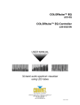
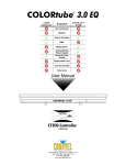
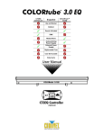
LED-T40A COLORtube™ 2.0 USER MANUAL CHAUVET, 3000 N 29th Ct, Hollywood, FL 33020 U.S.A (800) 762-1084 – (954) 929-1115 FAX (954) 929-5560 www.chauvetlighting.com 2005-11-16/12:32 Table of Content BEFORE YOU BEGIN....................................................................................................................................................... 3 WHAT IS INCLUDED .......................................................................................................................................................................................................... 3 UNPACKING INSTRUCTIONS .............................................................................................................................................................................................. 3 AC POWER ..................................................................................................................................................................................................................... 3 SAFETY INSTRUCTIONS .................................................................................................................................................................................................... 3 INTRODUCTION ............................................................................................................................................................... 4 FEATURES ....................................................................................................................................................................................................................... 4 OPTIONS ......................................................................................................................................................................................................................... 4 PRODUCT OVERVIEW....................................................................................................................................................................................................... 4 SETUP .............................................................................................................................................................................. 5 MOUNTING ...................................................................................................................................................................................................................... 5 CONNECTION DIAGRAM ................................................................................................................................................................................................... 5 OPERATING INSTRUCTIONS .......................................................................................................................................... 6 OVERVIEW....................................................................................................................................................................................................................... 6 STAND-ALONE OPERATION .............................................................................................................................................................................................. 6 APPENDIX ........................................................................................................................................................................ 7 MAINTENANCE ................................................................................................................................................................................................................. 7 RETURNS PROCEDURE .................................................................................................................................................................................................... 7 CLAIMS ........................................................................................................................................................................................................................... 7 TECHNICAL SPECIFICATIONS ............................................................................................................................................................................................ 8 TECHNICAL SUPPORT ...................................................................................................................................................................................................... 8 LED-T40A COLORtube™ 2.0 User Manual 2 2005-11-16/12:32 BEFORE YOU BEGIN What is included COLORtube™ 2.0 1 x LED-T40A COLORtube™ 2.0 1 x LED-PC5A power cord Mounting hardware Manual and Warranty Card Notice! The LED COLOR - - - -™ 2.0 System Series is not compatible with the previous non 2.0 system. Unpacking Instructions Immediately upon receiving a product, carefully unpack the carton, check the contents to ensure that all parts are present, and have been received in good condition. Notify the shipper immediately and retain packing material for inspection if any parts appear damaged from shipping or the carton itself shows signs of mishandling. Save the carton and all packing materials. In the event that a fixture must be returned to the factory, it is important that the fixture be returned in the original factory box and packing. AC Power To determine the power requirements for a particular product, see the label affixed to the back plate of the product or refer to the product’s specifications chart. A product’s listed current rating is its average current draw under normal conditions. All fixtures must be powered directly off a switched circuit and cannot be run off a rheostat (variable resistor) or dimmer circuit, even if the rheostat or AC Voltage Switch Example dimmer channel is used solely for a 0% to 100% switch. Before applying power, check that the source voltage matches the product’s requirement. Check the product or device carefully to make sure that if a voltage selection switch exists that it is set to the correct line voltage you will use. Warning! If applicable, verify that the power select switch on your unit matches the line voltage applied. All fixtures must be connected to circuits with a suitable Earth Ground. Safety Instructions Please read these instructions carefully, which includes important information about the installation, usage and maintenance? Please keep this User Guide for future consultation. If you sell the unit to another user, be sure that they also receive this instruction booklet. Always make sure that you are connecting to the proper voltage and that the line voltage you are connecting to is not higher than that stated on decal or rear panel of the fixture. This product is intended for indoor use only! To prevent risk of fire or shock, do not expose fixture to rain or moisture. Make sure there are no flammable materials close to the unit while operating. The unit must be installed in a location with adequate ventilation, at least 50cm from adjacent surfaces. Be sure that no ventilation slots are blocked. Always disconnect from power source before servicing or replacing lamp or fuse and be sure to replace with same lamp source. Caution! Secure fixture to fastening device using a safety chain. Never carry the fixture solely by its head. Use its carrying handles. Maximum ambient temperature is Ta: 45°. Do not operate fixture at temperatures higher than this. In the event of serious operating problem, stop using the unit immediately. Never try to repair the unit by yourself. Repairs carried out by unskilled people can lead to damage or malfunction. Please contact the nearest authorized technical assistance center. Always use the same type spare parts. Don’t connect the device to a dimmer pack. Make sure power cord is never crimped or damaged. Never disconnect power cord by pulling or tugging on the cord. Avoid direct eye exposure to lamp while it is on. There are no user serviceable parts inside the unit. Do not open the housing or attempt any repairs yourself. In the unlikely event your unit may require service, please contact CHAUVET. LED-T40A COLORtube™ 2.0 User Manual 3 2005-11-16/12:32 INTRODUCTION Features COLORtube™ 2.0 Features 144 LED's (48 red, 48 green, 48 blue) Ultra bright LED's Built-in stand alone programs Color range red, green, yellow, blue, purple, cyan, white 22 patterns, chase, sound-active, auto and color flows with variations via LED-CHVA COLORcontrollerTM 2.0 Up to 100,000-hour LED life span Architectural, retail, concealed coving, display, club, mood, accent lighting IP 44 rated for exterior use Milky white UV coated optically diffused polycarbonate Aluminum base housing Easy installation Energy saving and Eco-friendly Options Optional LED-CHVA COLORcontrollerTM 2.0 for operation DMX-compatible via LED-CHVA COLORcontrollerTM 2.0 Sound active via LED-CHVA COLORcontrollerTM 2.0 Automatic via LED-CHVA COLORcontrollerTM 2.0 Product Overview LED Tube Locking plates 4 pin connector used for control signal. Main plate 2 pin connector used for power. Mounting hardware provided LED-T40A COLORtube™ 2.0 User Manual 4 2005-11-16/12:32 SETUP Mounting Locking plates Center plate mounting hole Flat mounting surface Main plate LED Tube Place the LED tube on a flat surface and position both mounting plates at opposite ends. Using a pencil trace out the area of the mounting plates so that you can return the plate to the same location in order to screw or affix it to the surface. Once both plates are affixed to a permanent surface, place the tube directly over the plate and assemble the remaining hardware as illustrated. For a more secure fit, consider the use of 2 washers on each screw hole. Also notice the orientation of the locking plates. Connection Diagram LED-CHVA Controller LED-PC5A Power cable connects to AC outlet The diagram above illustrates the tubes connected in series or as required for normal operation. The controller is an optional item, although it is highly desirable because of its control features. Both plugs are unique in that one is a 2-pin and the other a 4-pin. Connect each tube in series by each matching connector and plug. The 2-pin connector is used for power. The 4-pin connector is used for signal. For every 30 tubes connected you will need a signal booster (LED-BOOSTA) and a power connection (LED-PC5A) to a different AC outlet. LED-T40A COLORtube™ 2.0 User Manual 5 2005-11-16/12:32 OPERATING INSTRUCTIONS Overview The COLORtube™ 2.0 is a one meter long tube containing 144 high intensity LEDs. Each tube has 4 leads: Signal in and power in on one end and signal out and power out on the other. The first tube must be connected to the mains power via a power cable (LED-PC5A). The other tubes may be powered via the power out cable limited only by the wattage available from the power outlet. The COLORtube™ 2.0 can be run using the LED-CHVA COLORcontroller™ 2.0. Up to 1000 tubes may be controlled by a single controller however a signal booster (LED-BOOSTA) is required for every 30 tubes. Stand-Alone Operation Immediately upon powering the COLORtube™ 2.0 will run a standard built in chase program. The built-in stand-alone program will run in sync on other tubes connected in series without any additional setup or settings. Please review the Connection Diagram on the page prior for instructions. If using the optional LED-CHVA COLORcontroller™ 2.0, loss of power to the controller will also revert the tube into its stand-alone operation. LED-T40A COLORtube™ 2.0 User Manual 6 2005-11-16/12:32 APPENDIX Maintenance To maintain optimum performance and minimize wear fixtures should be cleaned frequently. Usage and environment are contributing factors in determining frequency. As a general rule, fixtures should be cleaned at least twice a month. Dust build up reduces light output performance and can cause overheating. This can lead to reduced lamp life and increased mechanical wear. Be sure to power off fixture before conducting maintenance. Unplug fixture from power. Use a vacuum or air compressor and a soft brush to remove dust collected on external vents and internal components. Clean all glass when the fixture is cold with a mild solution of glass cleaner or Isopropyl Alcohol and a soft lint free cotton cloth or lens tissue. Apply solution to the cloth or tissue and drag dirt and grime to the outside of the lens. Gently polish optical surfaces until they are free of haze and lint. Do not to touch the lamp glass when cleaning fixture. Oil and dirt can cause damage and premature aging of the lamp. In the event that the lamp is touched or becomes dirty, clean the lamps with an alcohol wipe. The cleaning of internal and external optical lenses and/or mirrors must be carried out periodically to optimize light output. Cleaning frequency depends on the environment in which the fixture operates: damp, smoky or particularly dirty surrounding can cause greater accumulation of dirt on the unit’s optics. Clean with soft cloth using normal glass cleaning fluid. - Always dry the parts carefully. - Clean the external optics at least every 20 days. Clean the internal optics at least every 30/60 days. Returns Procedure Returned merchandise must be sent prepaid and in the original packing, call tags will not be issued. Package must be clearly labeled with a Return Merchandise Authorization Number (RA #). Products returned without an RA # will be refused. Call CHAUVET and request RA # prior to shipping the fixture. Be prepared to provide the model number, serial number and a brief description of the cause for the return. Be sure to properly pack fixture, any shipping damage resulting from inadequate packaging is the customer’s responsibility. CHAUVET reserves the right to use its own discretion to repair or replace product(s). As a suggestion, proper UPS packing or double-boxing is always a safe method to use. Claims Damage incurred in shipping is the responsibility of the shipper; therefore the damage must be reported to the carrier upon receipt of merchandise. It is the customer's responsibility to notify and submit claims with the shipper in the event that a fixture is damaged due to shipping. Any other claim for items such as missing component/part, damage not related to shipping, and concealed damage, must be made within seven (7) days of receiving merchandise. LED-T40A COLORtube™ 2.0 User Manual 7 2005-11-16/12:32 Appendix Technical Specifications WEIGHT & DIMENSIONS Length......................................................................................................................... 88.9 mm (3.5 in) Width........................................................................................................................... 81.3 mm (3.2 in) Height ......................................................................................................................... 53.3 mm (2.1 in) Weight.......................................................................................................................... 2.27 Kgs (5 lbs) CONSTRUCTION Tube Composition ............................................ Milky white UV coated optically diffused polycarbonate Exterior Rating .............................................................................................................................. IP44 POWER Power................................................................................................................................. 90V – 240V Current draw .................................................................................... (16.8W @ 120V), (8.4W @ 230V) Maximum linkable quantity on (1) power connection ............................................................. 30 pieces LEDS High Intensity LEDS ....................................................................................................... 100,000 hr life Red, Green, Blue .................................................................................................... 48 each (144 total) ENVIRONMENTAL Maximum ambient temperature ............................................................................ 0°C to 40°C (104° F) Humidity Range.................................................................................. 0-95% non-condensing humidity ORDERING INFORMATION Accessories for COLORtube™ 2.0 System Power Extension 15’ ..................................................................................................... LED-EXTP15A Power Extension 5’ ......................................................................................................... LED-EXTP5A Power Cable (Direct to Outlet)............................................................................................. LED-PC5A Signal Cable Extension 15’............................................................................................... LED-SIG15A Signal Cable Extension 5’ .................................................................................................. LED-SIG5A Signal Booster................................................................................................................LED-BOOSTA COLORcontroller™ 2.0 .......................................................................................................LED-CHVA COLORtube™ 2.0 LED Tube ............................................................................................... LED-T40A Technical Support Address: Service Dept. 3000 N 29th Ct, Hollywood, FL 33020 (U.S.A.) Support (Email): [email protected] Telephone: (954) 929-1115 - (Press 4) Fax: (954) 929-5560 - (Attention: Service) Website:............................................................................................... http://www.chauvetlighting.com LED-T40A COLORtube™ 2.0 User Manual 8 2005-11-16/12:32