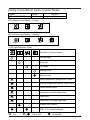
1
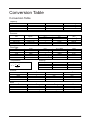
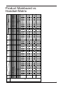
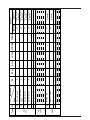
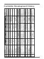
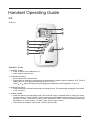
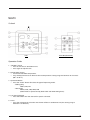
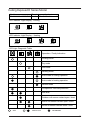
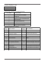
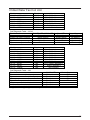
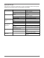
Service
Guide
Book
Table of Contents
Model Name
Product Name Description
Nomenclature
2
3
Conversion Table
Conversion Table
6
Product Mainboard vs. Handset Matrix
Product Mainboard vs. Handset Matrix 7
Controller Development History
Controller Development History
9
Handset Operating Guide
G6
G7 G11
G17
SLM3
Sequential LCD
Netware 3
11
13
15
17
19
21
23
Controller Configuration
Auto Random Restart
Hot Keep Selection
Auxiliary Heater Conversion
Multi Split Conversion
Sequential Controller
Chilled Water Fan Coil Unit – W1V3
Chilled Water Fan Coil Unit – W2.0
25
26
27
28
29
34
35
Service Diagnosis
Self Diagnosis Table
General Check
General Troubleshooting Guide
36
56
57
Appendix
Resistance – Temperature Characteristic
Appendix-1
1
Multi Split AC Inverter Condensing Unit
Multi Split DC Inverter Condensing Unit
Horizontal Condensing Unit
Vertical Condensing Unit
Air Cooled Roof Top Packaged Air
Conditioner
Air Cooled Inverter Mini Chiller
17
18
19
20
21
22
Description
Wall Mounted Fan Coil Unit
Wall Mounted AC Inverter Fan Coil Unit
Wall Mounted DC Inverter Fan Coil Unit
Ceiling Exposed Fan Coil Unit
Ceiling Cassette Fan Coil Unit
Ceiling Concealed Fan Coil Unit
Ducted Split Blower Unit
Chilled Water Fan Coil Unit
Water Source Heatpump Split Unit
Horizontal Water Source Heatpump Unit
Air Cooled Mini Chiller
Single Split Condensing Unit
Single Split AC Inverter Condensing Unit
Single Split DC Inverter Condensing Unit
Modular Split Condensing Unit
Multi Split Series
No.
1
2
3
4
5
6
7
8
9
10
11
12
13
14
15
16
5ACV
Generic Model Name
WM / 5WM
WMV
5WMX
CE / 5CE
CK / 5CK
CC / 5CC
SB
CW
WSS / 5WSS
WH
AC / 4AC / 5AC
SL / 4SL / 5SL
SLV
5SLX
MSS / 4MSS
MSD / 4MSD
MST / 4MST
MSH
MSV
5MSX
HDC / 5HDC
VCU
RT / 4RT
M5ACV
McQuay Brand
MWM / M5WM
MWMV
M5WMX
MCM / M5CM
MCK / M5CK
MCC / M5CC
MDB
MCW
MWSS / M5WSS
MWH
MAC / M4MAC / M5MAC
MLC / M4LC / M5LC
MLCV
M5LCX
MMC / M4MC
MMSD / M4MSD
MMST / M4MST
MMSH
MMSV
M5MSX
MHDC / M5HDC
MVCU
MRT / M4RT
Model Name
Product Name Description
2
Nomenclature
Indoor Unit
Others
A : First Issue
Grille Type
A : Grille A
Air Treatment Devices & Control
I : Negative Ion
L : Bare Unit
Market Region
C : Export with CE mark
Electrical
A : 220-240V/1Ph/50Hz
F : 380-415V/3Ph/50Hz
M
WM
010
G
R
-
A
C
I
A
A
Model Type
R : Heat Pump
Omitted if Cooling Only
Series
G : G Series
Capacity
010 : 10,000 Btu/h
Model Name
WM : Wall Mounted
CK : Ceiling Cassette
Refrigerant
5 : R410A
Omitted if R22
Brand
M : McQuay
3
Indoor Unit
Product Specifications Variation
AA : Revision
Connection Type
F : Flare
X : Not Applicable
Electrical
A : 220-240V/1Ph/50Hz
F : 380-415V/3Ph/50Hz
M
WM
010
G
W
-
A
X
A
A
Piping
H : 4 Pipes System
Omitted if 2 pipes system
Model Type
R : Heat Pump
W : Chilled Water Fan Coil
Omitted if DX Cooling Only
Series
G : G Series
Capacity
010 : 10,000 Btu/h
Model Name
WM : Wall Mounted
CK : Ceiling Cassette
Refrigerant
5 : R410A
Omitted if R22
Brand
M : McQuay
4
Indoor Unit
Others
A : First Issue
Specifications Variation
O : Standard Unit
I : Gold Fins
G : Low Ambient Unit
H : High Ambient Unit
Compressor
P : Panasonic
M : Mitsubishi
Market Region
C : Export with CE mark
Electrical
A : 220-240V/1Ph/50Hz
F : 380-415V/3Ph/50Hz
M
LC
010
C
R
-
A
C
P
O
A
Model Type
R : Heat Pump
Omitted if Cooling Only
Series
C : C Series
Capacity
010 : 10,000 Btu/h
Model Name
LC : Single Split Condensing Unit
MC : Modular Split Condensing Unit
Refrigerant
5 : R410A
Omitted if R22
Brand
M : McQuay
5
Conversion Table
Conversion Table
Capacity
Btu/hr
1
1000
3.968
3412
MBH
0.001
1
0.004
3.412
kCal/Hr
0.252
252
1
860.04
kW
-3
0.293 x 10
0.293
-3
1.162 x 10
1
Pressure
kg/cm
1
14.22
-2
3.61 x 10
-4
1.45 x 10
0.07
1
-3
2.538 x 10
-4
0.1 x 10
Flow Rate
W.G.
3
L/s
1
0.278
1000
0.063
0.472
m /hr
3.6
1
3600
0.227
1.7
(ft.)
2.309
32.84
0.083
-4
3.349 x 10
Pascal
(Pa)
4
0.69 x 10
4
9.81 x 10
248.84
1
3
U.S. GPM
15.85
4.403
15850
1
7.481
CFM
2.119
0.588
2119
0.1337
1
m/s
0.305
1
0.005
fpm
60
196.9
1
m /s
0.001
-3
0.278 x 10
1
-3
0.063 x 10
-3
0.472 x 10
Temperature
Velocity
fps
1
3.281
0.017
°F = (18 x °C) + 32
o F 32
oC 1.8
Volume
L
1
1000
3.785
28.315
Area
(in.)
27.7
394.08
1
0.004
2
PSI
2
in
1
144
1550.06
0.155
3
U.S. G.P.M.
0.264
264
1
7.48
2
m
-4
6.452 x 10
0.093
1
-4
1 x 10
m
0.001
1
-3
3.785 x 10
0.028
ft
-3
6.94 x 10
1
10.764
-3
1.076 x 10
2
3
ft
0.0353
35.3
0.134
1
2
cm
6.452
929.03
4
1 x 10
1
6
DX
Type
12
11
10
1
2
3
4
5
6
7
8
9
No.
Main Board (IC)
Model
WM - F Series
WM - G Series
WMS - G Series
CK - A/B/C Series
CE - D Series
CE - E Series
CC - C Series
CC - D Series
SB - B/C Series
SB 75 – 100B/BR
SB 125 – 150B/BR
SB 125CR
SB 150B2/BR2 – 600B4/BR4
SB – D/ER Series
SB 75 – 100D/ER
SB 125 – 150D/ER
SB 125D2 – 500D4
SB 125ER2 – 600ER4
RT Series
RT 55 – 120A/AR
RT 150 – 420A/AR
WMX – G Series
CKX – A/C Series
CEX – E Series
CCX – C Series
X
X
X
L2.0
X
X
X
X
X
X
X
L208A
X
X
X
X
U1SB125
X
X
X
X
SQ2.0
X
X
X
X
VA2.0
SLM3
SQ-LCD
G11
G7
G11
SLM3
SLM3
SLM3
SQ-LCD
SQ-LCD
SLM3
SLM3
SLM3
SQ-LCD
G7
G11
G11
G7
G7
G11
SLM3
Netware 3
Standard
Optional
Handset
SLM3 + AC5300
SLM3 + AC5300
SLM3 + AC5300
Netware 3
Netware 3
-
Netware 3
-
SLM3 + AC5300 / Netware 3
SLM3 + AC5300 / Netware 3
SLM3 + AC5300 / Netware 3
SLM3 + AC5300 / Netware 3
SLM3 + AC5300 / Netware 3
SLM3 + AC5300 / Netware 3
Netware 3
SLM3
Product Mainboard vs.
Handset Matrix
7
8
WSHP
Mini
Chiller
CW
FCU
Type
5WMWS – GR
5CKWS – AR/CR
20
21
5CCWS – CR
WH – B Series
WH 11 – 20B/BR
WH 25 – 70B/BR
CC – CW Series
SB – BW Series
AC – C Series
AC 20 – 60C/CR
AC 80 – 150C/CR
5AC 20 – 25C/CR
5AC 30 – 55C/CR
17
18
19
22
23
CE – EW Series
16
X
X
X
X
CE – DW Series
15
CK – AW/AWH/CW
Series
14
W2
X
Main Board (IC)
WM – GW Series
Model
13
No.
X
X
MCH1
X
X
MC1.0
X
X
X
LWS2.0
X
APM01CB
X
APM02D
SLM15A
APW04A
SLM3
G7
G7
C. Panel
C. Panel
C. Panel
C. Panel
SLM3
N/A
G11
G7
G7
G11
Standard
-
SLM3 + AC5300 /
Netware 3
SLM3 + AC5300 /
Netware 3
Netware 3
SLM3 + AC5300 /
Netware 3
SLM3 + AC5300 /
Netware 3
SLM3 + AC5300 /
Netware 3
SLM3 + AC5300 /
Netware 3
Netware 3
-
Optional
Handset
Challenger 2.2
Challenger 2.4
Challenger 2.4
Challenger 5
1996
1997
1998
1998
2002
2002
U1.4
Inverter
VA1.9 (Indoor)
VB1.0 (Outdoor)
Sequencer Controller
D2.0
Mini Chiller SZMC01
2001
D2.0
2001
G7
G7
G7 Turbo
-
G6 / G7
-
SLM3 /
Netware 2 (optional)
SQ-LCD
-
-
-
-
SLM3 (4 core wire)
G6
G6
G6
U1.4
2001
2001
Netware 1
Sequential Controller
G6
SLM2 (10 core wire)
-
2001
-
G3 & G6
-
-
-
-
Wired
G3
G6
Handset
G3 & G6
G3 & G6
G3
G3
Wireless
Sequential Controller
Universal Board
D1.0
U1.3
Chilled Water W1V2
2001
2000
Challenger C3A
Challenger C3B
Challenger C3B
Mini Chiller MCH01
Challenger 2.1 & 2.2
1996
1999
Main Board
Year
Model
Heating
WM 10/15DR
WM 20/25CR
WM10/15DR
WM 20/25CR
WM 07/10ER
WM 10/15FR
CK (15/20/25/30)B
SB (150-500)D
WM30F
-
WM (10-25)F
AC/4AC (40-58)A,
AC/4AC75-125B
CE-D / CK-A / CC-C
WM (10-25)F
-
WMV10FR
SLV10BR
SB (150-500)DR
WM (10-25)FR,
WM30FR
CK (15/20/25/30)BR
WM (10-25)FR
CE-DR / CK-AR /
CC-CR
AC/4AC (40-58)AR,
AC/4AC75-125BR
WM 07/10E
WM 10/15F
CK-A
CK-AR
CE-C/D
CE-CR/DR
CC-B/MSB/HSB
CC-R/MSB-R/HSB-R
AC (40-125)B
AC (40-125)BR
WM-FW / CE-DW / CC-CW / CK-AW / HSBBW
SB (150-500)B
SB (150-500)BR
-
Cooling
WM 10/15D
WM 20/25C
WM 07/10E
WM 10/15D
WM 20/25C
Cooling & heatpump
Multiple compressor
Cooling only
Heatpump only
In set form only
Cooling & Heatpump
Cooling only
Cooling & Heatpump
Cooling only
Heatpump only
Multiple compressor
Convertible PCB
Cooling & Heatpump
Copper sensor
Copper sensor
Remarks
Controller Development History
9
10
Sequential Controller, SQ
U1.4
L2.0
MC01
MCH01
L208A
2003
2004
2004
2004
2005
MC01
L208A
Sequential Controller, SQ
Chilled Water W2
2005
2006
2006
2006
2005
U1.4
Universal U1SB125
Sequential Controller, SQ
Inverter
VA2.0
Universal U1SB125
2003
2005
G11
-
Multi Split Indoor, MS10.0
Mini Chiller MCH03A
2002
2003
-
SML3 / Netware 3
SLM3
SQ-LCD
-
G7 & G11
SLM3 / Netware 3
G7 & G11
Chiller Panel
-
G11
-
G7
G11
Chiller Panel
Chiller Panel
Netware 3
SLM3
SLM3 – single speed
SQ-LCD
SQ-LCD
SLM3 – single speed
Wired
SLM3 /
Netware 2 (optional)
SC302
-
-
G7
-
G6
Chilled Water W1V3
2002
Handset
Wireless
Main Board
Year
Heating
WMS (10-20)FR
AC/4AC (80-150)CR
SB (125/150)
BR1/CR1/DR1
RT/4RT (60-120)AR
RT/4RT (150300)AR
SB 150BR2-600BR4
SB125DR2-500DR2
CK (10-20)CR
WM (07-15)GR
WM (20-25)GR
AC (80-150)CR
AC (20-60)CR
CE (15-28)ER
CC (75-100)DR
SB (75-100)ER
SB (125-150)ER1
SB 125ER2-600ER4
5WMX (10-25)GR
5SLX (10-25)CR
5AC (030-055)CR
CE-D / CK-A/B/C /
CE-DR / CKCC-C
AR/BR/CR / CC-CR
SB (75-100)B/D
SB (75-100)BR/ER
RT (360-420)A
RT (360-420)AR
WM-GW / CE-DW / CE-EW / CC-CW / CKAW/AWH/CW / SB-BW
SB 150B2-600B4
SB 125D2-500D4
CK (10-20)C
WM (07-15)G
WM (20-25)G
AC (80-150)C
AC (20-60)C
CE (15-28)E
CC (75-100)D
RT/4RT (150-300)A
AC/4AC(80-150)C
SB (125/150)
B1/C1/D1
RT/4RT (60-120)A
WM-FW / CE-DW / CC-CW / CK-AW / CK-BW
Model
Cooling
Cooling & Heatpump
Cooling & Heatpump
Heatpump only
In set form only
Heatpump only
Cooling & heatpump
Cooling & heatpump
Cooling & heatpump
Cooling & heatpump
Cooling & heatpump
Cooling & heatpump
Cooling & heatpump
Cooling & heatpump
Valveless application
only
Auto random restart
Cooling & heatpump
Remarks
Handset Operating Guide
G6
Outlook
8
2
TEMP
7
6
5
4
3
FAN
MODE
TIMER
SLEEP
1
SWING
Operation Guide
1. “ON/OFF” Switch
v Press to start the air conditioner unit.
v Press again to stop the unit.
2. Temperature Setting
v Set the desire room temperature.
v Press button to increase or decrease the set temperature. Setting range are between 16°C TO 30°C
setting (60°F to 80°F) (Optional setting from 20°C to 30°C).
Press
or
button simultaneously will toggle the temperature setting between °C and °F.
3. Automatic Air Swing
v Press the button to activate the automatic air swing function. The swing angle ranging from horizontal
to 25o to bottom.
4. “SLEEP” MODE
v Press the button to activate sleep mode. This mode can only be activated while in cooling or heating
mode operation. If it is activated in “COOL” mode, the set temperature will be increase 0.5°C after 30
minutes, 1°C after 1 hour and 2°C after 2 hours. Whereas in “HEAT” mode, the set temperature will
decrease by 1°C after 30mins, 2°C after 1 hour and 3°C after 2 hours.
v This function is available under COOL, HEAT & AUTO mode.
11
5. Timer Setting
v Press set button to activate the timer setting (from 1 hour to 15 hour) of the air conditioning unit. It will
be in “On” or “Off” condition after the set time depending to the current condition (either from “On” to
Off” or vise versa)
v To cancel the timer setting, press the button continuously until the timer display goes off.
6. Operation Modes
v Press the “mode” button for select the type of operating mode.
v Cooling only unit:
Cool m Dry m Fan.
v Heatpump unit:
Auto m Cool m Dry m Fan m Heat
7. Fan Speed and Ventilation Mode Selection
Press the button until the desired fan speed is achieved.
8. Signal Transmission Indication
Blink to confirm the last setting has been send to the unit.
12
G7
Outlook
1
2
MIN
HR
F
C
AUTO
AM
PM
ON
OFF
4
3
6
12
MODE
ON TIM
ER
7
SET
SWING
F TI
OF
CLR
SET
CLOCK
MER
CLR
EP
SLE
5
8
10
9
11
Operation Guide
1. Transmission Source
v The source where the signal will be transmitted.
2. Signal Transmission Indication
v Blink to confirm the last setting has been send to the unit.
3. On/Off Button
v Press once to start the air conditioner.
v Press again to stop the unit.
4. Temperature Setting
v To set the desired room temperature, press the button to increase or decrease the set
temperature.
v The temperature setting range is from 16°C to 30°C (Optional setting 18°C to 30°C).
v Press both buttons simultaneously to toggle the temperature setting between °C and °F.
13
5. Operation Mode
v Press the MODE button to select the type of operating mode.
v For cooling only unit, the available modes are : COOL, DRY & FAN.
v For heat pump unit, the available modes are : AUTO, COOL, DRY, FAN & HEAT.
6. Fan Speed Selection
v Press the button until the desired fan speed is achieved.
7. On Timer Setting
v Press the SET button will activate the on timer function.
v Set the desired on time by pressing the SET button continuously. If the timer is set to 7.30am, the air
conditioner will turn on at 7.30 sharp.
v Press the CLR button to cancel the on timer setting.
8. Off Timer Setting
v Press the SET button will activate the off timer function.
v Set the desired off time by pressing the SET button continuously.
v Press the CLR button to cancel the off timer setting.
9. Automatic Air Swing (Optional)
v Press the SWING button to activate the automatic air swing function.
v To distribute the air to a specific direction, press the SWING button and wait until the louver move to
the desired direction and press the button once again.
10. Sleep Mode Setting
v Press the button to activate sleep mode. This function is available under COOL, HEAT & AUTO
mode.
v When it is activated in COOL mode, the set temperature will be increased 0.5°C after 30mins, 1°C
after 1 hour and 2°C after 2 hours.
v When it is activated in HEAT mode, the set temperature will be decreased 1°C after 30mins, 2°C
after 1 hour and 3°C after 2 hours.
11. Clock Time Setting
v Press button + or - to increase or decrease the clock time.
12. Turbo Function (Optional – Only Applicable To Inverter Unit)
v Press button for fast cooling or heating operation.
v The temperature will be increased internally if it is in the HEAT mode, decreased if in COOL or DRY
mode. Fan speed will be increased if it is not at maximum speed.
v The temperature & fan speed will resume to user setting if the button is pressed again or after
20mins.
v Available under HEAT, COOL & DRY modes only.
14
G11
Outlook
2
1
4
8
10
3
5
6
7
12
11
9
Operation Guide
1. “ON/OFF” Button
v Press once to start the air conditioner unit.
v Press again to stop the unit.
2. Temperature Setting
v To set the desired room temperature, press the ▲ button to increase or ▼ button to decrease the
set temperature.
v The temperature setting range is from 16°C to 30°C.
v Press both buttons simultaneously to toggle ▲ and ▼ from °C to °F setting.
3. Operation Mode
v Press the MODE button to select the type of operating mode.
v
For cooling only unit, the available modes are: COOL ( e), DRY (S) and FAN (D).
v
For heat pump unit, the available modes are: AUTO, COOL ( e), DRY (S), FAN (D ) and HEAT (
).
15
4. Fan speed selection
v
Press the D button continuously will toggle the fan speed in the following order: Low (
v
Med (
) –––: High (
) –––: Auto
Stop pressing when the desired fan speed appears on the display screen.
) –––:
5. ON Timer Setting
v Press the SET button will activate the on timer function.
v Set the desired on time by pressing the SET button continuously. If the timer is set to 7.30am, the
air conditioner will turn on at 7.30am sharp.
v Press the CLR button to cancel the on timer setting.
6. OFF Timer Setting
v Press the SET button will activate the off timer function.
v Set the desired off time by pressing the SET button continuously.
v Press the CLR button to cancel the off timer setting.
7. Automatic Air Swing
v Press the SWING (
) button to activate the automatic air swing function.
v To distribute the air to a specific direction, press the SWING button and wait until the louver move
to the desired direction and press the button once again.
8. Sleep Mode Setting
v Press the SLEEP button will activate the sleep mode function. This function is available under
COOL, HEAT and AUTO mode.
v When the unit is operating under cooling mode, the set temperature is increased by 0.5°C after 30
minutes, 1°C after an hour, and 2°C after 2 hours.
v When the unit is operating under heating mode, the set temperature is decreased by 1°C after 30
minutes, 2°C after an hour and 3°C after 2 hours.
9. Clock Time Setting
v Press + button to increase the clock time.
v Press – button to decrease the clock time.
10. Turbo Mode
v
Press the TURBO (
) button to achieve the required set temperature in a short time.
11. Ionizer
v
Press the
button to activate the negative Ion function, which will refresh the indoor air effectively.
12. Personalize Setting
v Press J button and hold for 3s to initiate personalized setting
v Set the individual setting e.g. MODE, SET TEMP or FAN SPEED and leave for 4s to save the
setting into the programme.
v 2 groups of settings are allowed to store in the handset. Press once to activate the P1 setting,
press again to cycle between P1 and P2.
v Press any key to deactivate the personalize setting.
16
G17
Outlook
1
2
P1 P2
10
9
3
MODE
4
SET
OFF TIMER
SET
ON TIMER
14
13
8
SLEEP
7
CANCEL
15
CANCEL
11
5
12
6a 6b
Operation Guide
1. Transmission Source
v The source where the signal will be transmitted.
2. Signal Transmission Indication
v Blink to confirm that the last setting has been transmitted to the unit.
3. Temperature Setting
v To set the desired room temperature, press the ▲ or ▼ button to increase or decrease
the set temperature.
v The temperature setting range is from 16°C to 30°C (optional setting 20°C to 30°C).
4. Personalize Setting
v Press
and hold for 3s, then
v
v
v
P1
will blink. Press again to cycle between
P1
and
P2
.
Set the desire setting, then leave the handset for 4s without pressing any key and it will
save the setting into the programme.
Press once to activate the P1 setting, press again to cycle between P1 and P2.
Press any key to deactivate the personalize setting.
17
5. Automatic Air Swing (optional)
v Press the SWING
button to activate the automatic air swing function.
v To distribute the air to a specific direction, press the SWING
button and wait until the louver
move to the desired direction and press the button once again.
6a. Silent Function
v Press
for quiet operation.
v Fan speed turn to minimum speed.
v Press again to deactivate the function.
6b. Ionizer Function
v Press button to activate the negative ion function, which will refresh the indoor air effectively.
7. Sleep Mode Setting
v Press the SLEEP button will activate the sleep mode function. This function is available under
COOL, HEAT and AUTO mode.
v When the unit is operating under cooling mode, the set temperature is increased by 0.5°C after
30 minutes, 1°C after an hour, and 2°C after 2 hours.
v When the unit is operating under heating mode, the set temperature is decreased by 1°C after 30
minutes, 2°C after an hour, and 3°C after 2 hours.
8. Operating Mode
v Press the MODE button to select the type of operating mode.
v For cooling only unit, the available modes are: COOL ( e ), DRY (
) and FAN (
).
9. Fan Speed Selection
v Press the
button continuously will toggle the fan speed in the following order:
Low
Med
High
Auto
v Stop pressing when the desired fan speed appears on the display screen.
10. “ON/OFF” Button
v Press one to start the air conditioner unit.
v Press again to stop the unit.
11. Timer Cancel
v Press the TIMER CANCEL button to cancel the on timer setting.
12. OFF Timer Setting
v Press the OFF TIMER button will activate the off timer function.
v Set the desired off time by pressing the OFF TIMER button continuously.
13. ON Timer Setting
v Press the ON TIMER button will activate the on timer function.
v Set the desired on time by pressing the ON TIMER button continuously. If the timer is set to
7.30am, the air conditioner will turn on at 7.30am sharp.
14. Turbo Function
v Press
for fast cooling.
v Fan speed turn to maximum speed.
v Press again to deactivate the function.
15. Clock Time Setting
v Press
and hold to set the clock time.
18
SLM3
Outlook
SLM
AC-5300 (OPTIONAL)
Operation Guide
1. “ON/OFF” Switch
v Press to start the air conditioner unit.
v Press again to stop the unit.
2. Temperature Setting
v Set the desired room temperature.
v Press button to increase or decrease the set temperature. Setting range are between 16 oC to 30 oC
(60 oF to 80 oF).
3. Operation Modes
v Press the “mode” button for select the type of operating mode.
- Cooling Only:
COOL, DRY, FAN
- Heat Pump:
AUTO, COOL, DRY, HEAT, FAN
(AUTO mode is represented by both COOL and HEAT LED light on)
4. Fan Speed Selection
v Press the button until the desired fan speed is achieved.
5. Timer
v Press the set button to select the switch timer of the air conditioner unit (the setting range is
between 1 to 10 hours).
19
6. “SLEEP” Mode
v Press button to activate the sleep function. This function can only be activated under “cool” or heating
mode operation. When it is activated under “cool” mode operation, the set temperature will increase
0.5°C after 30 minutes, 1°C after 1 hour and 2°C after 2 hours. If it is activated under “HEAT” mode
operation, the set temperature will be decreased 0.5°C after 30 minutes, 1°C after 1 hour and 2°C
after 2 hours.
7. Air Swing
v Press button to activate the automatic air swing function.
8. Sensor
v Infra red sensor to receive signals from wireless controller.
9. LED Display
v To display the set temperature (in °C) and timer delay setting (in hours).
10. Transmission Source
v To transmit signals to the air conditioner.
20
Sequential Controller
Outlook
A : Time display
B : Error indication
C : Compressor running display (up to 4 compressors)
D : Key lock display
E : Heat display (up to 2 heaters)
F : Energy saving mode display
G : Compressor defrost cycle display (up to 4 compressors)
H : Operation mode display
I : Temperature set display
Operating Guide
1. “ON/OFF” Switch
• Press once to start the air conditioning unit.
• Press again to stop the unit.
• The operation lamp next to the key lights up and goes off respectively when the unit is running or not running.
• Caution : In the case when the ON/OFF key is pressed immediately after the operation is stopped, the unit will not restart until 3 minutes later to protect the compressor.
2. Selecting Operating Mode
• Press the MODE key to select the type of operating mode. Consecutive press of the key switches the operation over “COOL”, “HEAT”, “AUTO” and “FAN”
3. SAVE Mode
• Press the SAVE key to select the energy saving function. This option is only available for “COOL”, “HEAT” and “AUTO” modes.
21
4. Auxiliary Electric Heater
• If the “HEAT” mode provides insufficient heating to a room even at the highest temperature setting (30°C), press the HEATER key to activate the auxiliary electric heater. For models with two heaters, consecutive press of the key allows the selection of one or both heaters active.
5. Temperature Setting
• To set the desired room temperature, press ▲ or ▲ to increase or decrease the set temperature in the range of 16°C to 30°C.
• Press both ▲ and ▲ simultaneously to toggle between °C and °F setting.
6. Time Setting
Real time clock
• Press the CLOCK key once to activate set clock mode.
• Press again to disable set clock mode.
• Under set clock mode, the time of the present day can be set by pressing the respective MINUTE, HOUR and DAY key.
7 Days Timer
• Press the ON TIMER key to activate auto ON timer mode. Under this mode, press the respective MINUTE, HOUR and DAY key to select the time of the week when the air-
conditioning unit is to automatically start running. Press ON TIMER key again to save the setting.
• Press the OFF TIMER key to activate auto OFF timer mode. Under this mode, press the respective MINUTE, HOUR and DAY key to select the time of the week when the air-conditioning unit is to automatically stop running. Press the ON TIMER key again to save the setting.
• Then to activate the 7 days timer, press and hold the TIMER ACTIVE key until the word “TIMER ACTIVE” appears on the LCD screen. Repeat the same step to disable the 7 days timer.
7. Other Function
Key Lock
• Press the MINUTE key 3 times consecutively to activate the key lock. A “KEY LOCK” symbol will appear on the LCD screen. At this point, only the ON/OFF key is valid.
• To disable the key lock, again press the MINUTE key 3 times consecutively.
Test Run
• Press the TEST RUN key 2 times consecutively to test run the unit.
22
Netware 3
Outlook
4
5
6
3
7
2
1
8
1.
2.
3.
4.
5.
6.
7.
8.
Time display
Key lock display
Error indication
Fan speed display
Operation mode display
Sleep mode display
Air swing display
Temperature set display
Operating Guide
1. “ON/OFF” Switch
• Press once to start the air conditioning unit.
• Press again to stop the unit.
• The operation lamp next to the key lights up and goes off respectively when the unit is running or not running.
• Caution : In the case when the ON/OFF key is pressed immediately after the operation is stopped, the unit will not restart until 3 minutes later to protect the compressor.
2. Selecting Operating Mode
• Press the MODE key to select the type of operating mode. Consecutive press of the key switches the operation over “COOL”, “HEAT”, “AUTO”, “DRY” and “FAN”
3. Fan Speed Selection
• Press the FAN key until the desired fan speed is achieved.
23
4. Sleep Mode Setting
• Press the SLEEP key to activate sleep mode. This function is available under COOL, HEAT & AUTO mode.
• When it is activated in COOL mode, the set temperature will be increased 0.5°C after 30mins, 1°C after 1 hour and 2°C after 2 hours.
• When it is activated in HEAT mode, the set temperature will be decreased 1°C after 30mins, 2°C after 1 hour and 3°C after 2 hours.
5. Temperature Setting
• To set the desired room temperature, press ▲ or ▲ to increase or decrease the set temperature in the range of 16°C to 30°C.
• Press both ▲ and ▲ simultaneously to toggle between °C and °F setting.
6. Air Swing
• Press the SWING key to activate the automatic air swing function.
7. Time Setting
Real time clock
• Press the CLOCK key once to activate set clock mode.
• Press again to disable set clock mode.
• Under set clock mode, the time of the present day can be set by pressing the respective MINUTE, HOUR and DAY key.
7 Days Timer
• Press the ON TIMER key to activate auto ON timer mode. Under this mode, press the respective MINUTE, HOUR and DAY key to select the time of the week when the air-
conditioning unit is to automatically start running. Press ON TIMER key again to save the setting.
• Press the OFF TIMER key to activate auto OFF timer mode. Under this mode, press the
respective MINUTE, HOUR and DAY key to select the time of the week when the air conditioning unit is to automatically stop running. Press the ON TIMER key again to save the setting.
• Then to activate the 7 days timer, press and hold the TIMER ACTIVE key until the word “TIMER ACTIVE” appears on the LCD screen. Repeat the same step to disable the 7 days timer.
8. Other Function
Key Lock
• Press the MINUTE key 3 times consecutively to activate the key lock. A “KEY LOCK” symbol will appear on the LCD screen. At this point, only the ON/OFF key is valid.
• To disable the key lock, again press the MINUTE key 3 times consecutively.
24
Controller Configuration
Auto Random Restart
• Shorted at JH/JP1/J_LST jumper at main board for auto restart (supplied).
• Remove the jumper to have non-auto restart.
D2.0
U1.5 / SQ2.0
L2.0 / L208A / LW2 / W2
25
Hot Keep Selection
Three selections available:
a. Fan stop if indoor coil temperature < 30°C (OFF).
b. Fan runs at low speed if indoor coil temperature < 30°C and stop if indoor coil temperature < 18°C (ON).
c. Cycle of low fan running for 30s and fan off for 120s and repeat (INTERVAL).
WM – F/FR (U1.5)
3 selections available at the slide switch on the On/Off Switch Board; Preset at OFF.
Other models (U1.5)
At CN3 location on the PCB,
i. Remove the connector to have (b) Fan ON and
ii. Cut off the big resistor (12kOhm) to have (c) Fan INTERVAL
Non-ducted Model – standard setting is (a) Fan OFF
Ducted Model – standard setting is (C) Fan INTERVAL
26
Auxiliary Heater Conversion
To convert the standard U1.5 heatpump PCB to with auxiliary heater application, the following
components need to be added onto the PCB.
1. Heater relay
2. Transistor
3. Diode
27
Multi Split Conversion
Cooling Only Model (L2.0 / L208A)
The cooling only model WM-G, CK-A/B/C, CE-E, CC-C which are using L2 control board can be
switched to multi split units without any modification needed.
Heatpump Model (L2.0 / L208A)
WM-GR
The Multi Split mode can be selected at the slide switch on the On/Off Switch Board; Preset
at OFF.
The outdoor coil sensor has to be removed from the PCB as the reading is taken from the
outdoor PCB directly.
CK-AR/BR/CR, CE-ER, CC-CR
The Multi Split mode can be selected by disables the outdoor coil sensor and replace with a
dummy resistor 4.7kOhm (provided in the accessory bag).
28
Sequential Controller
It is allowed to configure the controller to suit individual’s need with details below:
Model Selection
1. Number of Compressor
The control can be configured into 4 main type’s base on number of compressors by changing “R42” values:
Item
1
2
3
4
Type
Single compressor
2 compressors
3 compressors
4 compressors
R value
3k
7.5k
22k
OPEN
2. Models
For each type, there are 3 models for the control to configure into.
a. Cooling (SQCn)
b. Heatpump + no heater (SQHn0)
c. Heatpump + 1 heater (SQHn1)
d. Heatpump + 2 heater (SQHn2)
e. Auto heatpump + no heater (SQHn0)
f. Auto heatpump + 1 heater (SQHn1)
g. Auto heatpump + 2 heater (SQHn2)
Dip switch 1
Off
On
Off
On
On
Off
On
Dip switch 2
Off
Off
On
On
Off
On
On
Dip switch 5
Off
Off
Off
Off
On
On
On
n denotes number of compressor(s)
where the postfix number indicates number of compressor(s).
3. Stage Differential Temperature
Differential temperature is the temperature difference between turning on or off 1 compressor to
another compressor in thermostat cycle.
The stage differential temperature can be selected from the range shown below:
a. Default
b. 0.5°C
c. 1.0°C
d. 1.5°C
Dip switch 3
Off
On
Off
On
Dip switch 4
Off
Off
On
On
Note that 1.5°C only valid for 2 and 3 compressors model. For 4 compressors model, maximum
allowed is 1.0°C.
29
The default differential temperature is base on number of compressor model, the setting is as
below:
Model
1 compressor
2 compressors
3 compressors
4 compressors
Diff. Temperature
Not. Applicable
0.5°C
1.0°C
1.5°C
4. Hot Keep Option
Dip switch 6
Off
On
a. Fan off
b. Fan on
5. Operating Modes
The system has 4 operating modes to select with respect to each model selection:
Model
SQCn
SQHnh
SQHnh
Where
Auto
X
Cool
X
X
X
Heat
X
X
Fan
X
X
X
(Dip switch 5 = off)
(Dip switch 5 = on)
x denotes modes available
n = number of compressor(s)
h = number of heater(s)
6. Last Memory Functions
The power up settings for either with or without the last memory backup is based on the JH1
setting.
a. Last memory backup
b. Without last memory backup
JH1 Setting
JH1 Plugged
JH1 Removed
30
7. Sequential Control for Cool Mode
The starting sequence for indoor fan, outdoor fan and compressors is shown as below:
Start
2 seconds
15 seconds
15 seconds
15 seconds
15 seconds
Indoor fan
Outdoor fan 1
Outdoor fan 2
Outdoor fan 3
Outdoor fan 4
2 seconds
2 seconds
2 seconds
2 seconds
Compressor 1*
Compressor 2*
Compressor 3*
Compressor 4*
*If available and applicable
The compressors will be turned on one by one depending on the on/off conditions shown in the
above.
8. Sequential Control for Heat Mode
The starting sequence for indoor fan, outdoor fan and compressors is shown as below:
Start
2 seconds
15 seconds
15 seconds
15 seconds
15 seconds
15 seconds
Indoor fan
Outdoor fan 1
Outdoor fan 2
Outdoor fan 3
Outdoor fan 4
Heater 1*
2 seconds
2 seconds
2 seconds
2 seconds
2 seconds
15 seconds
All 4 way valves
Compressor 1*
Compressor 2*
Compressor 3*
Compressor 4*
Heater 2*
*If available and applicable
The compressors will be turned on one by one depending on the on/off conditions shown in
theabove.
31
9. Conversion from Old Sequential Board to New Sequential Board
(For wiring up to 1000 meters)
9.1 Sequential Main Board SQMB01 (Old Version)
U8
Rework instruction:
SQMB01 (Main Board) from
old version to new version
Step 1:Remove Jumper J1 and J2.
Step 2:Add Part: 2051-MAX1483
IC :MAX1483 to U8
J1 & J2
9.2 Sequential Main Board SQMB01 (New Version)
32
9.3 Sequential Main Board SQMB01 (New Version)
Part: 2051-MAX1483 IC
:MAX1483
Jumper J1 and
J2 removed
9.4 Sequential LCD Panel SQ-LCD (New Version)
SQLCD (LCD Panel) from old to new
Step 1: Remove Jumper: J1, J2
Step 2: Add Chip Resistor. 1/10W 5% 200K
to R8, R9, R10
Step 3: Add Part: 1000000030
IC: SMD MAX1483CSA to U4
33
Chilled Water Fan Coil Unit (W1V3)
The standard W1V3 board comes with a VALVE jumper. The system can be configured as the
jumper selection listed below:
VALVE jumper
Heatpump Mode & Valve Application
Heatpump Mode & Valveless Application
Cooling Mode & Valve Application
Cooling Mode & Valveless Application
√ : Jumper Remained
HEAT jumper
X
X
X
X
X : Jumper Removed
VALVE & HEAT Jumper Location
Model: WM 05-25FW
1. VALVE jumper is plugged into JVLV connector on the emergency switchboard.
2. HEAT jumper is plugged into JMODE connector on the emergency switchboard.
Model: CK 20-50AW, CK 15-25BW, CK 10-20CW, CE 20-50DW and CC 10-60CW
1. VALVE jumper is plugged into JVLV connector on the main board.
2. HEAT jumper is plugged into the OD connector on the main board.
34
Chilled Water Fan Coil Unit (W2.0)
The system model can be configured via the following jumpers. For each model selected, the
permissible operating modes are as follows:
Jumper
M1
M2
M3
M4
Configuration
2 Pipes without Aux. Heater
2 Pipes with Aux. Heater
4 Pipes + Boiler
4 Pipes + Boiler
Model
1
2
3
4
Operating Modes
Heat>Cool>Dry>Fan
Heat>Cool>Dry>Fan
Heat>Cool>Dry>Auto>Fan
Heat>Cool>Dry>Fan
M1
M2
M3
M4
The standard W2.0 board comes with a VALVE jumper. The system can be configured as the
jumper selection listed below:
VALVE jumper
Heatpump Mode & Valve Application
Heatpump Mode & Valveless Application
Cooling Mode & Valve Application
Cooling Mode & Valveless Application
√ : Jumper Remained
HEAT jumper
X
X
X
X
X : Jumper Removed
VALVE & HEAT Jumper Location
1. VALVE jumper is plugged into JVLV connector on the emergency switchboard.
2. HEAT jumper is plugged into JMODE connector on the emergency switchboard.
35
Service Diagnosis
Self Diagnosis Table
Wall Mounted F Series Cooling Only Model
Model
Board
Handset
WM 10/15/20/25F, 311
D2.0
G7
LED Indicator Light Display
TIMER
POWER
SLEEP
DRY
LED Light Diagnosis Table
Operation / Faulty Indication
Timer On
/
Sleep mode On
Dry mode
/
Continuously
Room air sensor contact loose / short
Once every 2 sec
Indoor coil sensor contact loose / short
Twice every 2 sec
Gas leak
3 times every 2 sec
ON
Defrost mode
/
ON or OFF
BLINKING
36
Wall Mounted F Series Heat Pump Model
Model
Board
Handset
WM 10/15/20/25FR, 301R
U1.5
G7
LED Indicator Light Display
/
COOL
(Green)
DRY
(Orange)
HEAT / FAN
(Red / Green)
SLEEP
(Red)
LED Light Diagnosis Table
Operation / Faulty Indication
/
Cooling mode
Dry mode
Fan mode
/
Heating mode
/
Auto mode in heating operation
/
Auto mode in cooling operation
Defrost mode
Compressor overload protection
Indoor coil sensor contact loose
/ short
Outdoor coil sensor contact
loose / short
Room air sensor contact loose /
short
Gas leak
ON
/
ON or OFF
BLINKING
37
Wall Mounted G Series Model
Model
Board
Handset
WM 10/15/20/25G/GR
L2.0
G11 / SLM3 / Netware 3
LED Indicator Light Display
SLEEP
COOL / HEAT
TIMER
IONIZER
LED Light Diagnosis Table
Operation / Faulty Indication
COOL/HEAT
(GREEN/RED)
/
Green
/
Cooling mode
/
Red
/
Heating mode
/
Red
/
Auto mode in heating operation
/
Green
/
Auto mode in cooling operation
Timer On
Sleep mode On
Ionizer On
/
Fan mode On
/
Dry mode On
Room air sensor contact loose / short
1 time
Outdoor coil sensor contact open
3 times
Indoor coil sensor contact open
2 times
1 time
Defrost mode
Red
3 times
6 times
ON
Compressor overload protection /
Indoor coil sensor short /
Outdoor coil sensor short
/
ON or OFF
Gas leak
Hardware error (tact switch pin short)
BLINKING
38
Ceiling Cassette A / B / C Series Model
Model
CK 20/25/30/40/50A/AR
CK 15/20/25B/BR
CK 10/15/20C/CR
Board
U1.5
U1.5
U1.5
Handset
G7 / SLM3 / Netware 3
G7 / SLM3 / Netware 3
G7 / SLM3 / Netware 3
LED Indicator Light Display - Cooling
POWER
TIMER
SLEEP
LED Indicator Light Display – Heating
POWER
TIMER
HEAT
LED Light Diagnostic Table
Operation / Faulty Indication
Cooling mode
Timer On
Sleep mode On
Heating mode
/
Continuously
Compressor overload protection
Once every 3 sec
Pump fault
Twice every 3 sec
Gas leak
3 times every 3 sec
Room / indoor / outdoor coil sensor contact
loose / short
4 times every 3 sec
ON
Frost prevention mode
/
ON or OFF
BLINKING
39
Ceiling Cassette A / B / C Series Model
Model
CK 20/25/30/40/50A/AR
CK 15/20/25B/BR
CK 10/15/20C/CR
Board
L208A
L208A
L208A
Handset
G7 / SLM3 / Netware 3
G7 / SLM3 / Netware 3
G7 / SLM3 / Netware 3
LED Indicator Light Display - Cooling
POWER
TIMER
SLEEP
LED Indicator Light Display – Heating
POWER
TIMER
HEAT
LED Light Diagnostic Table
Operation / Faulty Indication
Cooling mode
Timer On
Sleep mode On
Heating mode
Auto mode in cooling operation
Auto mode in heating operation
Compressor overload protection /
Indoor coil sensor short /
Outdoor coil sensor short
1 time
Pump fault
2 times
Gas leak
3 times
Room air sensor contact loose / short
1 time
Indoor coil sensor contact open
2 times
Outdoor coil sensor contact open
3 times
ON
/
ON or OFF
BLINKING
40
Ceiling Exposed D Series Model
Model
CE 20/25/30/40/50D/DR
Board
U1.5
Handset
G7 / SLM3 / Netware 3
LED Indicator Light Display - Cooling
COOL
DRY
FAN
LED Indicator Light Display – Heating
COOL
DRY
FAN
HEAT
LED Light Diagnostic Table
Operation / Faulty Indication
Cooling mode
Dry mode
Fan mode
Heating mode
Auto mode in cooling operation
Auto mode in heating operation
Defrost mode
Compressor overload protection
Gas leak
Outdoor coil sensor contact open / short
Indoor coil sensor contact open / short
Room air sensor contact loose / short
ON
/
ON or OFF
BLINKING
41
Ceiling Exposed D / E Series Model
Model
CE 20/25/30/40/50D/DR
CE 15/20/25/28E/ER
Board
L208A
L208A
Handset
G7 / SLM3 / Netware 3
G11 / SLM3 / Netware 3
LED Indicator Light Display - Cooling
COOL
DRY
FAN
LED Indicator Light Display – Heating
COOL
DRY
FAN
HEAT
LED Light Diagnostic Table
Operation / Faulty Indication
Cooling mode
Dry mode
Fan mode
Heating mode
Auto mode in cooling operation
Auto mode in heating operation
Compressor overload protection /
Indoor coil sensor short /
Outdoor coil sensor short
Gas leak
Outdoor coil sensor contact open
Indoor coil sensor contact open
Room air sensor contact loose / short
ON
/
ON or OFF
BLINKING
42
Seven Segment Display – SLM3 / Netware 3
Model
WM 10/15/20/25FR, 301R
CK 20 - 50A/AR
CK 15 - 25B/BR
CK 10 - 20C/CR
CE 20 - 50D/DR
CC 10 - 60C/CR
Board
U1.5
U1.5
U1.5
U1.5
U1.5
U1.5
Handset
SLM3 / Netware 3
SLM3 / Netware 3
SLM3 / Netware 3
SLM3 / Netware 3
SLM3 / Netware 3
SLM3 / Netware 3
Cooling / Heat pump Model
Seven Segments
Faulty Indication
E1 blinking
Room air sensor contact loose / short
E2 blinking
Indoor coil sensor contact loose / short
E3 blinking
Outdoor coil sensor contact loose / short
E4 blinking
Compressor overload protection
E5 blinking
Gas leak
E6 blinking
HEAT LED blinking
Pump fault*
Defrost mode (SLM3 only)
*Applicable for Ceiling Cassette Model only.
Model
WM 10/15/20/25G/GR
CK 20 - 50A/AR
CK 15 - 25B/BR
CK 10 - 20C/CR
CE 20 - 50D/DR
CE 15 - 28E/ER
CC 10 - 60C/CR
CC 30 - 100D/DR
Board
L2.0
L208A
L208A
L208A
L208A
L208A
L208A
L208A
Handset
SLM3 / Netware 3
SLM3 / Netware 3
SLM3 / Netware 3
SLM3 / Netware 3
SLM3 / Netware 3
SLM3 / Netware 3
SLM3 / Netware 3
SLM3 / Netware 3
Cooling / Heat pump Model
Seven Segments
Faulty Indication
E1 blinking
Room air sensor contact loose / short
E2 blinking
Indoor coil sensor contact open
E3 blinking
Outdoor coil sensor contact open
E4 blinking
Compressor overload protection /
Indoor coil sensor short /
Outdoor coil sensor short
E5 blinking
Gas leak
E6 blinking
Pump fault*
E7 blinking
Outdoor coil sensor exist (Multi-split model)
E8 blinking
Hardware error (tact switch pin short)
*Applicable for Ceiling Cassette Model only.
43
Ducted Blower B/C/D/ER Series Model – Single Compressor
Rooftop Packaged Air Conditioner – Single Compressor
Model
SB 75 – 100B/BR
SB 75 – 100D
SB 75 – 100ER
SB 125 – 150B/BR
SB 125CR
SB 125 – 150D
SB 125 – 150ER
Board
L208A
L208A
L208A
U1SB125
U1SB125
U1SB125
U1SB125
Handset
SLM3
SLM3
SLM3
SLM3
SLM3
SLM3
SLM3
RT 55 – 120A/AR
U1SB125
SLM3
Seven Segment Display – SLM3
Seven Segments
Faulty Indication
E1 blinking
Room air sensor contact loose / short
E2 blinking
Indoor coil sensor contact open
E3 blinking
Outdoor coil sensor contact open
E4 blinking
Compressor overload protection /
Indoor coil sensor short /
Outdoor coil sensor short
E5 blinking
Gas leak
44
Ducted Blower B/D/ER Series Model – Multi Compressors
Rooftop Packaged Air Conditioner – Multi Compressors
Model
SB 150B2/BR2 – 600B4/BR4
SB 125D2 – 500D4
SB 125ER2 – 600ER4
Board
SQ2.0
SQ2.0
SQ2.0
Handset
SQ-LCD
SQ-LCD
SQ-LCD
RT 150 – 420A/AR
SQ2.0
SQ-LCD
Error Code
When the system is on and an error occurs, the ON/OFF LED on the LCD panel will blink and an error
code is shown. When the system is off and there is a thermistor error, the ON/OFF LED is off but the error
code is still displayed. Each error code represents different message as below:
Error
Error
Faulty Indication
Faulty Indication
Code
Code
E01
E02
E03
E04
E05
E06
E07
E08
E09
E10
E11
E12
E13
Require manual reset (possible causes)
Compressor 1 high temperature
(overload)
Compressor 2 high temperature
(overload)
Compressor 3 high temperature
(overload)
Compressor 4 high temperature
(overload)
Compressor 1 high pressure trip /
contact open
Compressor 2 high pressure trip /
contact open
Compressor 3 high pressure trip /
contact open
Compressor 4 high pressure trip /
contact open
Compressor 1 trip / low refrigerant /
outdoor abnormal
Compressor 2 trip / low refrigerant /
outdoor abnormal
Compressor 3 trip / low refrigerant /
outdoor abnormal
Compressor 4 trip / low refrigerant /
outdoor abnormal
E19
Indoor coil sensor 4 short
E20
Indoor coil sensor 1 open
E21
Indoor coil sensor 2 open
E22
Indoor coil sensor 3 open
E23
Indoor coil sensor 4 open
E24
Outdoor coil sensor 1 short
E25
Outdoor coil sensor 2 short
E26
Outdoor coil sensor 3 short
E27
Outdoor coil sensor 4 short
E28
Outdoor coil sensor 1 open
E29
Outdoor coil sensor 2 open
E30
Outdoor coil sensor 3 open
E31
Outdoor coil sensor 4 open
E14
Room sensor short
E32
Compressor 1 de-ice
E15
Room sensor open
E33
Compressor 2 de-ice
E16
Indoor coil sensor 1 short
E34
Compressor 3 de-ice
E17
Indoor coil sensor 2 short
E35
Compressor 4 de-ice
E18
Indoor coil sensor 3 short
45
Wall Mounted F Series Inverter Model
Model
WMX 10/15FR
Board
VA2.0
Handset
G7
LED Indicator Light Display
/
COOL / DRY
Stand-by /
Fan
HEAT
TIMER
LED Light Diagnosis Table
Operation / Faulty Indication
/
Cooling mode
/
Dry mode
Stand-by / Fan mode
/
Heating mode
/
Auto mode
Defrost mode
Compressor overload protection
Indoor temperature sensors contact loose /
short
Outdoor temperature sensor contact loose /
short
Gas leak / compressor overheat
Communication error between indoor and
outdoor
Inverter error / PFC error
Outdoor total current trip / DC peak
Indoor fan feedback error
ON
/
ON or OFF
BLINKING
46
Wall Mounted G Series Inverter Model
Model
WMX 10/15/20/25G/GR
Board
VA3.0
Handset
G11
LED Indicator Light Display
SLEEP
COOL / HEAT
TIMER
IONIZER
LED Light Diagnosis Table
Operation / Faulty Indication
COOL/HEAT
(GREEN/RED)
Green
/
Cooling mode
Red
/
Heating mode
Orange
/
Auto mode
Timer On
Sleep mode On
Ionizer On
/
Fan mode On
/
Dry mode On
Defrost mode
Red
Indoor temperature sensor loose / short
Green
Coil temperature sensor loose / short
Outdoor temperature sensor loose / short
Compressor overload protection
Green
IPM / PFC error
Green
Outdoor total current trip / DC peak
Compressor overheat / gas leak
Indoor fan feedback error
Green
Communication error between indoor and
outdoor
ON
/
ON or OFF
BLINKING
47
Ceiling Cassette A/C Series Inverter Model
Model
CKX 20/25A/AR
CKX 10/15/20C/CR
Board
VA3.0
VA3.0
Handset
G11
G11
LED Indicator Light Display - Cooling
POWER
TIMER
SLEEP
LED Indicator Light Display – Heating
POWER
TIMER
HEAT
LED Light Diagnostic Table
Operation / Faulty Indication
Cooling mode
Timer On
Sleep mode On
Heating mode
Defrost mode
Indoor temperature sensor loose / short
1 time
Outdoor temperature sensor loose / short
2 times
Communication error
3 times
Compressor overload protection
4 times
Pump fault
5 times
Compressor overheat / gas leak
6 times
Outdoor over current
IPM / PFC / Partial switching
ON
/
ON or OFF
BLINKING
48
Ceiling Convertible E Series Inverter Model
Model
CEX 15/20/25E/ER
Board
VA3.0
Handset
G11
LED Indicator Light Display - Cooling
COOL
DRY
FAN
LED Indicator Light Display – Heating
COOL
DRY
FAN
HEAT
LED Light Diagnostic Table
Operation / Faulty Indication
Cooling mode
Dry mode
Fan mode
Heating mode
Defrost mode
Indoor temperature sensor loose / short
1 time
Outdoor temperature sensor loose / short
2 times
Communication error
3 times
Compressor overload protection
4 times
Pump fault
5 times
Compressor overheat / gas leak
6 times
Outdoor over current
IPM / PFC / Partial switching
ON
/
ON or OFF
BLINKING
49
Seven Segment Display
Model
WMX 10 – 25G/GR
CKX 20 – 25A/AR
CKX 10 – 20C/CR
CEX 15 – 25E/ER
CCX 10 – 25C/CR
Board
VA3.0
VA3.0
VA3.0
VA3.0
VA3.0
Handset
SLM3
SLM3
SLM3
SLM3
SLM3
Cooling / Heat pump Model
Seven Segments
Faulty Indication
E1 blinking
Indoor temperature sensor loose / short
E2 blinking
Outdoor temperature sensor loose / short
E3 blinking
Communication error
E4 blinking
Compressor overload protection
E5 blinking
Pump fault
E6 blinking
Compressor overheat / gas leak
E7 blinking
IPM / PFC / Partial switching
E8 blinking
Outdoor over current
E9 blinking
Indoor fan feedback error
50
Inverter Outdoor Unit
Model
SLX 10/15/20/25C/CR
MSV 25/35A
MSX 20/25/30A/AR
Normal running / compressor running RED LED blinking
No. of Blinks
Blinking Indication
1
Normal running, with no limitation
2
Voltage limit
3
Cooling unit: outdoor coil temperature limit
Heating unit: indoor coil temperature limit
4
Total current limit
5
Discharge temperature limit
6
Cooling unit: indoor coil temperature limit
7
Indoor fan control
8
Outdoor frequency adjustment
Compressor stopped RED LED blinking
No. of
Blinks
Faulty Indication
No. of
Blinks
Faulty Indication
1
Outdoor ambient sensor error
15
DC fan motor feedback error
2
Outdoor coil sensor error
16
AC peak current error
3
Outdoor discharge sensor error /
compressor overheat
17
Outdoor suction sensor error
4
DC compressor feedback error
18
None
5
Communication error
19
DC compressor speed control error
6
Over current error
20
None
7
No load
21
Outdoor suction pipe A sensor error
8
Over / under voltage
22
Outdoor suction pipe B sensor error
9
DC compressor start failure
23
Outdoor suction pipe C sensor error
10
Cooling overload
24
Outdoor suction pipe D sensor error
11
Defrost
31
Communication error with indoor A
12
IPM protection
32
Communication error with indoor B
13
Read EEPROM error
33
Communication error with indoor C
14
Write EEPROM error
34
Communication error with indoor D
51
Chilled Water Fan Coil Unit
Model
WM 05 – 25FW, 301W
CK 20 – 50AW/AWH
CK 15 – 25BW
CK 10 – 20CW
CE 20 – 50DW/CBW
CC 10 – 60CW
SB 75 – 150BW
Board
W1V3
W1V3
W1V3
W1V3
W1V3
W1V3
N/A
Handset
G7 / SLM3 / Netware 3
G7 / SLM3 / Netware 3
G7 / SLM3 / Netware 3
G7 / SLM3 / Netware 3
G7 / SLM3 / Netware 3
SLM3 / Netware 3
No Controller
Self Diagnostic Table – W1V3
Fault Indication
POWER LED / COOL LED
Other LEDs
Seven Segments
Room sensor missing
Blinks 4 times
FAN blinks
E1 blinking
Indoor coil sensor missing
Blinks 4 times
SLEEP blinks
E2 blinking
Pump fault
Blinks 2 times
COOL & FAN blink
E6 blinking
Pipe water temperature poor
Blinks 3 times
COOL & DRY blink
E4 blinking
Pipe water temperature fault
Blink 1 time
COOL blinks
E5 blinking
Model
WM 07 – 25GW
WM 301W
CK 20 – 50AW/AWH
CK 15 – 25BW
CK 10 – 20CW
CE 07 – 15CBW
CE 20 – 50DW
CE 15 – 25EW
CC 10 – 60CW
SB 75 – 150BW
Board
W2
W2
W2
W2
W2
W2
W2
W2
W2
N/A
Self Diagnostic Table – W2
Fault Indication
Room sensor error (short/open)
Pipe water sensor error (short/open)
Water pump error
Pipe water temperature fault
Window open activated*
Antifreeze mode activated*
Load shedding activated*
*Applicable for 4 pipes applications only.
Handset
G11 / SLM3 / Netware 3
G7 / SLM3 / Netware 3
G7 / SLM3 / Netware 3
G7 / SLM3 / Netware 3
G7 / SLM3 / Netware 3
G7 / SLM3 / Netware 3
G7 / SLM3 / Netware 3
G11 / SLM3 / Netware 3
SLM3 / Netware 3
No Controller
COOOL LED
Blink 1 time
Blink 2 times
Blink 6 times
Blink 5 times
Blink 3 times
Blink 7 times
Blink 8 times
Seven Segments
E1
E2
E6
E5
-
52
Wall Mounted G Series Model – Water Source Split Unit
Model
5WMWS 10/15/20/25GR
Board
LWS2.0
Handset
G11 / SLM3 / Netware 3
LED Indicator Light Display
SLEEP
COOL / HEAT
TIMER
IONIZER
LED Light Diagnosis Table
Operation / Faulty Indication
COOL/HEAT
(GREEN/RED)
/
Green
/
Cooling mode
/
Red
/
Heating mode
/
Red
/
Auto mode in heating operation
Green
/
Auto mode in cooling operation
/
Timer On
Sleep mode On
Ionizer On
Room air sensor contact loose / short
Outdoor coil sensor contact loose / short
Indoor coil sensor contact open
Compressor overload protection
Gas leak
Defrost mode
Red
ON
/
ON or OFF
BLINKING
53
Ceiling Cassette A / B / C Series Model – Water Source Split Unit
Model
5CKWS 20/25/30/40/50AR
5CKWS 10/15/20CR
Board
LWS2.0
LWS2.0
Handset
G7 / SLM3 / Netware 3
G7 / SLM3 / Netware 3
LED Indicator Light Display – Heating
POWER
TIMER
HEAT
LED Light Diagnostic Table
Operation / Faulty Indication
Cooling mode
Timer On
Heating mode
Auto mode in cooling operation
Auto mode in heating operation
Compressor overload protection
1 time
Pump fault
2 times
Gas leak
3 times
Room air sensor contact loose / short
1 time
Indoor coil sensor contact loose / open
2 times
Outdoor coil sensor contact loose / open
3 times
ON
/
ON or OFF
BLINKING
54
Seven Segment Display – SLM3 / Netware 3 (Water Source Split Unit)
Model
5WMWS 10/15/20/25GR
5CKWS 20 - 50A/AR
5CKWS 10 - 20C/CR
5CCWS 10 - 60C/CR
Board
LWS2.0
LWS2.0
LWS2.0
LWS2.0
Handset
SLM3 / Netware 3
SLM3 / Netware 3
SLM3 / Netware 3
SLM3 / Netware 3
Cooling / Heat pump Model
Seven Segments
Faulty Indication
E1 blinking
Room air sensor contact loose / short
E2 blinking
Indoor coil sensor contact loose
E3 blinking
Outdoor coil sensor contact loose
E4 blinking
Compressor overload protection /
Indoor coil sensor short /
Outdoor coil sensor short
E5 blinking
Gas leak
E6 blinking
HEAT LED blinking
Pump fault*
Defrost mode (SLM3 only)
*Applicable for Ceiling Cassette Model only.
55
General Check
When any air conditioner malfunction is noted, immediately switch off the power
supply to the unit and contact the local dealer if necessary.
Problem Symptom
Check Item
The unit does not work Check the power supply
Fan does not work
Fan work, but
compressor does not
work
Air conditioner work
but cooling not
satisfactory
The air flow is too low
Check the fuse
Check the remote controller timer
setting
Check the power supply
Check the fan motor capacitor
Check the fan motor
Check the switch
Check if the thermostat setting too
high
Check the compressor capacitor
Check the compressor
Check the compressor contactor
Check if the thermostat setting too
high
Check if the condenser coil dirty
Check the condenser installation
condition
Diagnosis by service port pressure
and operating Current
Check the air filter
Check the fan / blower condition
The remote controller
light is dim
Check the battery
Suggested Action
Check to make sure that the rated
voltage is supplied.
Check and replace the fuse.
Make sure the delay timer is set
correctly.
Check to make sure that the rated
voltage is supplied.
Check and replace the capacitor.
Check and replace the fan motor.
Check and change the switch.
Reset thermostat.
Check and replace the capacitor.
Check and replace the compressor.
Check and replace the contactor.
Reset thermostat.
Clean the condenser coil.
Make sure the condenser is installed
according to factory’s recommendation.
Check for insufficient refrigerant.
Check and make sure the air filter is
clean.
Check and make sure that the fan /
blower are in good condition.
Check and replace the battery.
Make sure the batteries are correctly
inserted.
56
General Troubleshooting Guide
By means of pressure readings.
Low Side
High Side
Low Side
High Side
Low Side
High Side
Low Side
High Side
Too High
Normal
Probable Cause
A Little High
Circuit
High Side
Too Low
Data
A Little Low
Pressure
1. Overcharged with refrigerant.
2. Non-condensable gases in refrigerant circuit
(eg. Oil)
3. Obstructed air-intake / discharge.
4. Short circuit of hot air at condensing unit.
1. Poor compression / no compression
(compressor defective).
2. Check valve stick in open position.
3. Reversing valve leaking (for heatpump only).
1. Undercharged with refrigerant.
2. Refrigerant leakage.
3. Air filter clogged / dirty (indoor unit).
4. Indoor fan locked (cooling).
5. Defective defrost control, outdoor coil freeze
up (heating).
6. Outdoor fan locked (heating).
1. Outdoor fan blocked (cooling).
2. Outdoor coil dirty (cooling).
3. Indoor fan locked (heating).
4. Indoor filter clogged dirty (heating).
1. Air intake temperature of indoor unit too high.
Low Side
57
By means of diagnostic flow chart:
Generally, there are two kinds of problems, i.e. starting failure and insufficient
cooling/heating. “Starting failure” is caused by electrical defect while improper application
or defects in refrigerant circuit causes “Insufficient cooling / heating”.
i ) Diagnosis of Electric circuit
: Faulty
: Check
: Cause
: Remedy
No cooling/heating ( Unit fails to start )
Stop
Evaporator
fan motor
Faulty
Unit power
supply
Fuse for
operation
circuit
No voltage or low voltage
Wrong phase/missing
phase
Blown
Components shorted
Get the right voltage
Repair the power line
Repair or replace
the components
Connections loose
Tighten the connections
High or low voltage
Get the right voltage
Running
Over current
relay for
evaporator
fan
Tripped
Wrong phase/missing
phase
Faulty
Evaporator
fan contactor
Condenser
fan motor
Stop
Over current Tripped
relay for
condenser
fan
Running
1
2
Coil burned
Contact faulty
Check the power
supply to the motor:
repair when necessary
Change the contactor
Repair the contacts
Faulty fan motor
Repair or change
the motor
Defective operation
Repair or change
the switch
No voltage or low voltage
Wrong phase/missing
phase
Get the right voltage
Check the power
supply to the motor:
repair when necessary
58
1
2
Faulty
Condenser
fan contactor
Coil burnt
Change the contactor
Contact faulty
Change the contacts
Fan motor faulty
Other electrical
component faulty
Faulty
Compressor
contactor
Repair or change the motor
contactor
Repair or change if necessary
Coil burnt
Change the contactor
Contact faulty
Change the contacts
Open compressor
windings
Incorrect wiring
Change the compressor
Correct the wiring
The most common causes of air conditioner failure to “start” are :
a) Voltage not within p 10% of rated voltage.
b) Power supply interrupted.
c) Improper control settings.
d) Air conditioner is disconnected from main power source.
e) Fuse blown or circuit breaker off.
59
ii ) Diagnosis of Refrigerant Circuit / Application
There might be some causes where the unit starts running but does not perform
satisfactorily, i.e. insufficient cooling. Judgement could be made by measuring temperature
difference of indoor unit’s intake and discharge air as well as running current.
:
Faulty
: Check
: Cause
: Remedy
Insufficient cooling
Air
circulation
Restricted
Indoor / outdoor coil dirty
(clogged)
Indoor air filter dirty
Fan motor malfunction
High cooling
load
Refrigerant
circuit
Compressor
Clean the coil
Clean the filter
Change or repair
the motor
Obstruction at air inlet /
outlet of indoor / outdoor
unit
Remove the
obstruction
Excessive heat source.
e.g. electric kettle
Remove or reduce
heat source
Room overcrowded with
people
Reduce number
of people in the room
Windows / doors wide
open
Close the
windows / doors
Refrigerant short charge
or refrigerant leakage
Add refrigerant.
Repair leakage
if detected
Restriction e.g. at
strainer, capillary, filter
dryer, etc.
Less or no compression
(Low running current)
Repair clogging
or replace faulty
components
Replace compressor
Satisfactory operation with temperature difference of air
intake & discharge of indoor unit 8°C to 13°C. *
( * value is for reference only )
60
Insufficient heating
Restricted
Air
circulation
Indoor / outdoor coil dirty
(clogged)
Indoor air filter dirty
Fan motor malfunction
Obstruction at air inlet /
outlet of indoor / outdoor
unit
High heating
load
Refrigerant
circuit
Windows / doors wide
open
Refrigerant short charge
or refrigerant leakage
Restriction e.g. at
strainer, capillary, filter
dryer, etc.
Compressor
Less or no compression
(Low running current)
Clean the coil
Clean the filter
Change or repair
the motor
Remove the obstruction
Close the
windows / doors
Add refrigerant. Repair
leakage if detected
Repair clogging or
replace faulty components
Replace compressor
Satisfactory operation with temperature difference of air
intake & discharge of indoor unit 14°C to 20°C. *
( * value is for reference only )
61
62
v
v
v
Remedial Action
v Check power supply
v Look for short circuit or grounded wires in
motor windings
Replace fuses and reset circuit breakers
when the fault has been corrected
Check tightness and soundness of all
electrical connection
Defective contactor or coil
v Repair or replace
Unit is stopped because a safety has tripped v Determine the type of safety shut down and
correct the unit is restarted
Loose wires
v Check wire connection and tighten terminal
screw
Compressor faulty
v Contact local dealer
No power supply
v Check power supply
Fan motor faulty
v Contact local dealer
Thermostat setting too high
v Reset thermostat
Condenser coil dirty
v Contact local dealer
Obstacle blocking air inlet or outlet of the unit v Remove the obstacle
Insufficient refrigerant in the system
v Contact local dealer
Improper water flow rate
v Contact local dealer
Water in the system is contaminated
v Contact local dealer
Possible Causes
v No power supply
v Fuses blown or automatic circuit breakdown
open
v
2. Fan does not start v
v
v
3. Air conditioning
v
does work, but
insufficient cooling v
v
v
v
Symptoms
1. Compressor does
not start
When any malfunction is occurred, immediately switch off the power supply to the unit, and contact the local
dealer, if necessary. Some simple troubleshooting tips are given below:
Mini Chiller: Troubleshooting Guide
63
Switch (ON)
Cool air does not
come out
Compressor run but stops
immediately
Water or steam is discharged
from the unit
Fan runs but compressor
does not run
Switch (ON)
Air flow out
but it does
not cool enough
Troubleshooting
v Close the windows and doors
v Wait for a while (to protect the compressor,
a 3 minutes restart-preventing circuit is built
into the unit. Therefore, there are occasions
sometimes when the compressor does not
start running immediately. There are cases
when it does not run for as long as 3
minutes)
v For temperature control, decrease the set
temperature at cooling
v Can not be operated as it is out of
temperature control range
v Remove blocking matter
v After checking the set temperature and inlet
temperature adjust thermostat (23WA)
v Clean the filter
v Remove the obstacle
v Press the switch (ON) button after power
restoration.
v Turn the power supply ON
v Replace the fuse
v Put in the earth leakage breaker
v Modify the wiring phase of power supply
v At cooling, water which places to cooling v It is not a breakdown. Please use it as it is
piping and piping connection part drops
v The set temperature of thermostat
is too high
v The room temperature is excessively
low for cooling
v Air outlet and inlet are blocked
v The filter is filled with dust and dirt
v There are some obstacles at the air
inlet and outlet of the units
v Windows and doors are open
v The restart-preventing circuit is in
operation for 3 minutes
v The power supply is turned OFF
v The fuse in the power supply is gone
v The earth leakage breaker is gone
v The wiring phase of power supply is
mistaken
v Improper temperature adjustment
Before you ask for repair service, check the following points
Symptoms
Switch Box
Possible Causes
(Field Supply)
It does not run
Switch (ON) v Power failure
Rooftop: Troubleshooting Guide
Appendix
Resistance – Temperature Characteristics
Type
Material Name
Resistance
B Value
DTN-C1 03F3H-OYL 1128, 1148, 1158
3H
R25=10.000k + 1.0% - 1.0%
B25/30=3450K + 1.0% - 1.0%
t°C Rmin (k ) Rnom (k ) Rmax (k ) t°C
Rmin (k )
Rnom (k ) Rmax (k )
42
5.28E+00
5.37E+00
5.45E+00
44
4.92E+00
5.01E+00
5.09E+00
3.49E+01
46
4.59E+00
4.67E+00
4.76E+00
3.04E+01 3.11E+01
3.18E+01
48
4.29E+00
4.37E+00
4.42E+00
0
2.78E+01 2.84E+01
2.90E+01
50
4.01E+00
4.09E+00
4.16E+00
2
2.54E+01 2.59E+01
2.65E+01
52
3.75E+00
3.82E+00
3.90E+00
4
2.33E+01 2.37E+01
2.42E+01
54
3.51E+00
3.58E+00
3.65E+00
6
2.14E+01 2.18E+01
2.21E+01
56
3.29E+00
3.36E+00
3.43E+00
8
1.96E+01 2.00E+01
2.03E+01
58
3.08E+00
3.15E+00
3.22E+00
10
1.80E+01 1.83E+01
1.86E+01
60
2.89E+00
2.96E+00
3.01E+00
12
1.66E+01 1.69E+01
1.71E+01
62
2.71E+00
2.78E+00
2.84E+00
14
1.53E+01 1.55E+01
1.57E+01
64
2.55E+00
2.61E+00
2.67E+00
16
1.41E+01 1.43E+01
1.45E+01
66
2.40E+00
2.45E+00
2.51E+00
18
1.30E+01 1.32E+01
1.33E+01
68
2.25E+00
2.31E+00
2.37E+00
20
1.20E+01 1.22E+01
1.23E+01
70
2.12E+00
2.17E+00
2.23E+00
22
1.11E+01 1.12E+01
1.14E+01
72
2.00E+00
2.05E+00
2.10E+00
24
1.03E+01 1.04E+01
1.05E+01
74
1.88E+00
1.93E+00
1.98E+00
26
9.52E+00 9.62E+00
9.72E+00
76
1.77E+00
1.82E+00
1.87E+00
28
8.82E+00 8.92E+00
9.02E+00
78
1.67E+00
1.72E+00
1.77E+00
30
8.17E+00 8.27E+00
8.37E+00
80
1.58E+00
1.62E+00
1.67E+00
32
7.58E+00 7.68E+00
7.78E+00
82
1.49E+00
1.53E+00
1.58E+00
34
7.04E+00 7.14E+00
7.23E+00
84
1.41E+00
1.45E+00
1.49E+00
36
6.54E+00 6.64E+00
6.73E+00
86
1.33E+00
1.37E+00
1.41E+00
38
6.09E+00 6.18E+00
6.27E+00
88
1.26E+00
1.30E+00
1.34E+00
40
5.67E+00 5.75E+00
5.84E+00
90
1.19E+00
1.23E+00
1.27E+00
-10
4.42E+01 4.53E+01
4.65E+01
-8
4.02E+01 4.12E+01
4.22E+01
-6
3.66E+01 3.74E+01
3.83E+01
-4
3.33E+01 3.41E+01
-2
Appendix-1
Lot 60334, Persiaran Bukit Rahman Putra3,
Taman Perindustrian Bukit Rahman Putra,
P.O.Box 79, 47000 Sungai Buloh, Selangor D.E., Malaysia
Tel: 603-61458600 Fax: 60361412060
http://www.mcquayup.com