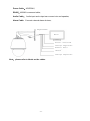
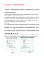
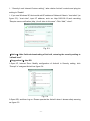
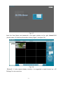
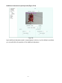
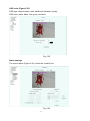
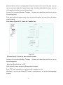
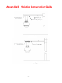
1
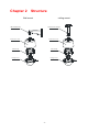
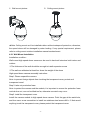
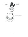
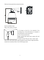
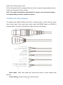
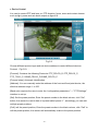
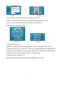
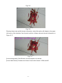
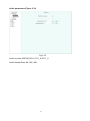
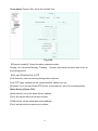
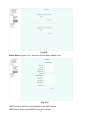
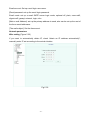
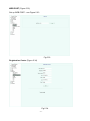
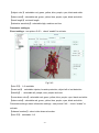
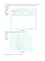
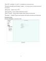
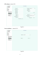
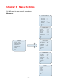
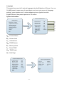
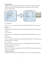
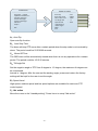
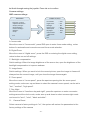
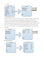
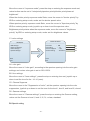
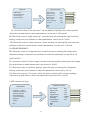
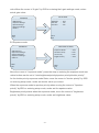
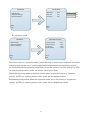
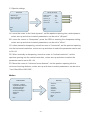
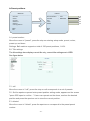
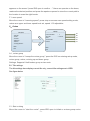
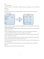
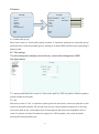
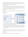
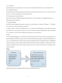
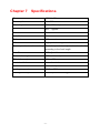
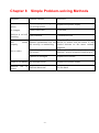
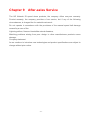
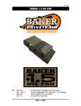
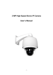
High Definition Intelligent Auto Tracking IP Speed Dome Camera User Manual -0- Content Chapter 1 Precautions....................................................................... 2 Chapter 2 Structure ........................................................................... 4 Chapter 3 Features ........................................................................... 5 Chapter 4 Installation Guide .............................................................. 7 Chapter5 Network Setup ................................................................. 16 Chapter 6 Menu Settings................................................................. 53 Chapter 7 Specifications.................................................................. 77 Chapter 8 Simple Problem-solving Methods ................................... 78 Chapter 9 After-sales Service ......................................................... 79 Appendix I Lightning and Surge ...................................................... 80 Appendix II Hoisting Construction Guide ......................................... 81 -1- Chapter 1 Precautions ● Please read this manual carefully before installation Note: This device is powered with AC24V. Please make sure the correct the power supply before connection. Inappropriate power supply may cause severe damage. ● Handle with care In transportation and storage process, we need to prevent stress, such as severe vibration, and immersion to avoid any damage to the product. This product must be carried disassembled and packaged, either in delivery to users or in return delivery to the factory for repairing. Damage caused by assembled transportation will not be covered by warranty. ● Install with care Handle the product carefully and gently. Prevent such incorrect operations as stress, severe vibration, or may lead to mechanical failure, affecting the overall performance of product; the electrical installation must comply with safety standards, with use of dedicated power adapter; Under the cover are advanced optical devices, avoid direct hand touch, for the sake of image quality; Control signals and video signals should maintain a sufficient distance from high-voltage equipment or cables in the transmission process, if necessary, take anti-lightning, anti-surge and other protective measures. Keep power off until the completion of all installation. ● Do not dismantle parts Do not dismantle internal parts, please turn to qualified maintenance professionals to carry out repairs. ● Keep the product away from electric or magnetic fields If the product is placed near TV, radio transmitters, electromagnetic devices, electric motors, transformers, loudspeakers in the vicinity, the electromagnetic fields generated by them would interfere the image. ●Do not point the camera at strong light Regardless of power on/off status, do not point the camera at the sun or very bright objects, do not point the camera at bright stationary objects for a long time, otherwise it will cause unrecoverable damage to the camera CCD. ● Maintenance with care It is advised to avoid collision or vibration. Do not use strong or abrasive detergents to -2- clean the dome body. When cleaning up dirt, use dry cloth. If dirt is uneasy to remove, swab with a neutral detergent. If there is sticky dust on the lens, please use the special lens paper. ●Working Environment Speed Dome Environmental temperature -40℃~+60℃ Moisture <95%(Non-condensing) Atmospheric pressure 86~106KPa Power AC/DC 24V/3.0A Note: make sure outdoor installation meets water-proof requirements -3- Chapter 2 Structure Wall mount ceiling mount Wall amount bracket Pendent mount bracket Protective cover Protective cover Dome body Dome body Gauge cover Gauge cover -4- Chapter 3 Features 3.1 Features 1. Built-in Decoder ● 1.3M HD IP Speed Dome(18x)support 720P 25/30fps output. ● 1.3M HD IP Speed Dome(30x)support 720P 25/30fps output. ● 2M HD IP Speed Dome(20x)support 1080P 25/30fps output. ● Support English menu ● Power-off protection, no data loss ● RJ-45 port network port ● Support PELCO_P、PELCO_D protocols。 ● Support 3D location ● 220 programmable presets ● 8 cruising tracks, each cruising track has 32 preset positions ● 8 auto scan tracks, the left and right boundaries and scan speed can be set ● 8 privacy zones ● Support OSD, date and time display ● Support 8 channel alarm input and 2 channel alarm output ● Support TF storage and local capture 2. Integrated Universal Speed Change Rotator ● Manual speed: 0.05°~180°/second, maximum speed: 550°/second ● Pan 360 °continuous rotation Tilt -15 °(can be set) ~ 90 °, and support auto-flip ● Stepless speed changing user-friendly zoom / speed auto-matching techniques ● Classic dual bearing structure, the operation is more stable Synchronous belt structure and precision stepper motor, responsive and accurate positioning 3. All-weather Outdoor Design ● Built-in heater ● Double housing structure ● IP66 water proof -5- 3.2 Function Instruction ● Focus/Rotate Auto Match Speed Dome can auto adjust pan and tilt rotation speed depending on the focus distance. ● Preset Position Setting and Calling Preset function means the speed dome can memory current pan/tilt angel, focus, zoom, ect. When need, it can be called upon directly. Our speed dome support up to 220 preset positions. ● Auto Scan Users can set the left and right boundaries by control keyboard. Then speed dome can scan between it. It can set up to 8 groups scan path. ● Auto Cruising Users can program some preset positions into auto cruising sequence, then the speed dome can track as it. Each cruising tracks has 32 preset positions. ● Pattern Tour Speed Dome can memory 180s running path. When start pattern tour, speed dome can track as recording path. It supports 4 groups pattern tour. ● Guard Location The dome will rotate back to preset position after a period of vacant time. ● Power-off Protection Speed dome can resume operation status before the power-off, no data loss. -6- Chapter 4 Installation Guide 4.1 Preparation 1. Tools: Please prepare the necessary tools according to specific situations 2. Check installation space and address Check the space is enough to install the speed dome. The wall must be thick enough to install the expansion screws and can bear 4 times the weight of the dome camera itself. 3. Please well keep the whole package After open the package, please well keep them in case need to return to manufacturer if any problem. ★Note:The non-original package may lead to damage during the transportation. 4.2: Installation There are two types of installation: 1:Wall mount 2:Ceiling mount -7- 1)Wall mount picture: 2)Ceiling mount picture ★Note: Ceiling mount can’t be installed outdoor without waterproof protection; otherwise, the speed dome will be damaged by water leaking. If any special requirement, please refer to ceiling mount outdoor installation manual as attachment. 4.2.1 Wall Mount Installation Installation condition: Wall mount high speed dome camera an be used in hard wall structure both indoor and outdoor ⑴The thickness of the wall should be enough to install expansion screw ⑵The wall can withstand at least four times the weight of the dome High speed dome camera assembly instruction: Step1: Please unpack the camera Note: to prevent foreign objects from touching the transparent cover, protect and transparent cover! Step 2: take out production foam Note: to protect the camera and the module, it is important to ensure the protection foam vertical slow out, can not be tilted too far, otherwise a scratch may occur. Step3: install the transparent cover Install the camera module to high speed dome camera. Point the gap at the waist-hole, and then use a cross screwdriver to install two stainless steel screws M4 × 6. Note avoid anything touch the transparent cover, please protect the transparent cover. -8- B A Clamp mark A Clamp mark B 4-M4X20 Captive screws -9- Wall mount high speed dome camera dimension: Specific installation steps: Step1: Drill a whole on the wall (1) As shown on the left, to the underside of the mounting holes of the wall bracket as a template to draw drill position on the wall and drill. (2) Put 4 screws into the hole. Step2: connect high speed dome camera with wall mount bracket As shown, put the PTZ power cable, network cable, alarm cable, audio cable, ground cable through the bracket, then put high speed dome camera into connection socket, fix the 3 M6 hexagon screw. - 10 - Rotate 90 degree Threading Raising Locking Step 3: Cable connection (see specific external line diagram) Step 4: Fix high speed dome on the wall Put the cables (including power, video cable, RS 485 and ground line) through the bracket. Then fix the speed dome base and the bracket with 4 screws and lock with ¢8 plain cushion and nut. Note: Do not let bracket suppress cable. Screw the nuts tight to avoid high speed dome camera drop. Fixed tube expanding screw Note: For outdoor use, please pay attention on veneer cracks and cable hole sealing to ensure waterproof. Above is the installation of cable, installer can also lead the cable out of the outlet on the side of the bracket. Step 5:Tear off the protection film Peel off the protective film transparent ball cap. Note: to prevent foreign objects such as - 11 - fingers dirty transparent cover surface. 4.2.2 Ceiling mount high speed dome installation Ceiling dome drawing: Ø45 Drill on the wall Step 1 :Draw the drill location and drill on the wall. Put the cables (including power, video cable, RS 485 and ground line) through the wall and leave it here. Put expansion bolt of M8 into the hole. Step2: Connect high speed dome camera and the ceiling mount bracket As shown below, put the PTZ power cable, network cable, alarm cable, audio cable, ground cable through the bracket, then put high speed dome camera into connection - 12 - socket, fix the 3 M6 X16 hexagon screw. Threading Rotate 90 degree Locking Raising Step 3: Cable connection (please refer to external connection drawing) Step4: install high speed dome camera with bracket Put the cables (including power, video cable, RS 485 and ground line) through the bracket. Then fix the speed dome base and the bracket with 4 M8 screws and lock with ¢8 plain cushion and nut. Note: do not let the bracket suppress the cable. Fixed tube expanding screw Note: Above is the installation of cable, installer can also lead the cable out of the outlet on the side of the bracket. - 13 - Step5: Tear off the protection film Peel off the protective film transparent ball cap. Note: to prevent foreign objects such as fingers dirty transparent dome surface. Note: The outdoor installation ceiling bracket is easy to cause the water leaking, for waterproofing measures, please see Annex. 4.3 External cable diagram The speed dome adopted 900mm lead wire, including: power, control (Internet), audio input, audio output, video, alarm input, alarm output and RS485 cables, and RS485 is reversed cable. Connection interface and cable colors are as following: AC 24V1/DC 24V+R ed AC 24V1/DC 24V-Green Lightning protection Green/Yellow 485A B lue 485B B lack Ground Green 1 Audio input Purple Audio Ground Green2 Audio output Yellow Alarm input Yellow 1.2.3.4.5.6.7.8 Alarm Ground Green 3 Alarm output 1 Norm ally open White Alarm output 1 Public White Alarm output 2 Norm ally open White Alarm output 2 Public White 1 2 3 4 Video Cable: BNC video cable can connect with monitor or other analog video devices; Control Cable:Connect computer or other devices; - 14 - Power Cable:AC/DC24V; RS485:485AB is reversed cable; Audio Cable: Audio input and output can connect mic and speaker; Alarm Cable:Connect external alarm devices; Video line to Monitor Monitor Power line, connect AC24V Alarm input、 Output interface RS 485 line, Reserve Cable base Audio input、 Output interface Note:please refer to labels on the cables - 15 - Chapter5 Network Setup ● Operation Requirement This system is advised to operate in the Windows XP operating system. In order to use and operate the system better, Please make sure below items setup or install correctly after this system installation. 1.Monitor resolution setup to: 1024x768 or more, color setup to Color (32 bit). Please refer to the Windows user manual or online help. 2.Please confirm install the fonts the system need in the operating system. For example the Chinese version system needs to install the Times New Roman font. If the system interface display abnormal, because of it maybe not install the system needed fonts or the fonts are damaged and need to reinstall the fonts. ● IE Setup If it is the first time to use S3 series network video products, please download the ActiveX control. Before download it needs to setup the IE browser to confirm download successfully. Notice: Please use the IE browser of Windows operating system , confirm the version is above 6.0 Please don’t use any third-party browser and any IE browser shell like Maxthon, FireFox, Window of the World, we do not ensure use these software can log on the network video server 【Suggestion 1】:Use IE6、IE7 1.Open the IE browser, Click "Tools-Internet Options Security Internet Custom Level (Figure 5.1), and set the items of ActiveX controls and plug-in to "Enable" (Figure 5.2). Fig.5.1 Fig.5.2 - 16 - 2. “Security-Local Internet-Custom setting”, take relative ActiveX controls and plug-ins setting to “Enable” 3.If you use Windows XP, that would add IP address of Network Video in “trust sites” (as figure 5.3): “trust sites”, input IP address, such as: http://192.168.1.2,and canceling “Require server verification (http:) for all sites in this zone”. Click “Add”, “close”. Fig. 5.3 【Notice】:After finished downloading of ActiveX, returning the security setting to “default level” 【Suggestion 2】:Use IE8 1.Open IE, Internet Zone- Modify configuration of ActiveX in Security setting, click “Prompt” of unsigned ActiveX as figure 5.4: Fig. 5.4 2.Open IE8, and then log on. Please operate the ActiveX when it shows safety warning as figure 5.5. - 17 - Fig. 5.5 3.Modify permission setting- Enable local directory path when uploading files to a server as figure 5.6. Fig. 5.6 【Notice】:It is suggested that the setting above mentioned should be return to safe level for your IE’s safety. ● System Log-on Ensure the PC and network video equipment’s IP address in the same network segment: etc. PC is 192.168.1.1, and network video equipment is 192.168.1.2. Open IE, inputting the IP address in address bar. Then click “go to”, it’ll show up as figure 5.7 meantime. If it has prompt about download the ActiveX with YES or NO, please check “YES”. After finished the downing in few minutes, the figure 5.7 will show up - 18 - Fig. 5.7 Input the User Name and password in the logon window on the right: Admin/1111 (correct case). It’ll link the picture after clicking “logon”. (As figure 5.8) Fig. 5.8 【Notice】: If video cannot display correctly, it is suggested to install ActiveX as < IE Setting> for one more time. - 19 - ● Device Control It is used to control PTZ and lens, ex. PTZ direction, focus, zoom and contact closure such as light, power and rain brush output as figure5.9 Fig.5.9 Choose different protocol type and set device address to control different devices. Protocol(Fig 5.10): [Protocol]: Contains the following Protocols: PTZ_PELCO_D, PTZ_PELCO_P, PTZ_TC615_P, DOME_PELCO_D DOME_PELCO_P. [Protocol state]: Automatic identification. [Address]: You can manually enter the address of the front-end fixed point device, the effective address range: 1 to 255. [Baud rate]: requires the user to enter the “configuration parameters "----" PTZ Settings” interface to set up. [Set]: Set the preset position; Enter the preset number in the blank column, click "Set" button, the camera’s current state of a preset called preset “1”; accordingly you can add multiple preset positions. [Call]: call the preset position; Enter the preset number in the blank column, click "Call" to call the preset position, the camera will automatically rotate to the preset position. - 20 - Fig.5.10 Fig.5.11 The lens Control and subsidiary control switch (Figure 5.11): [Zoom]: Control the camera lens zoom, optical zoom and electronic zoom. [Focus]: camera electronic focusing, use Auto Focus ineffective. [Iris]: manually control iris switch. Fig.5.12 Fig.5.13 PTZ control (Figure 5.12): [SPEED]: manually adjust the rotation speed of the PTZ, adjustable from 0 to 100. Eight-way control button, control PTZ movement in eight directions, the middle button in the eight-way control button is automatically scan button, click this button, the PTZ will rotate & auto scan; click the button again, it will stop turning. Video Parameters: (Figure 5.13): [Brightness] [Contrast] [Saturation] [Tint]: adjustable from 0 to 100 - 21 - ● Common parameter settings Click [General setting] to enter the General setting interface, as shown in Figure 5.14 Fig.5.14 Common settings [Channel Num]: the channel selection of the multi-channel network video equipment, such as: 4-channel network video server has 4 channels. [Set video cover area]: Check to set the video occluded region, including with the mouse to take effect after the area you want to block as shown in Figure 5.15 Figure black area in the upper-right corner of the block part of the picture, click on the Clear area back to normal as shown in Fig 5.16. - 22 - Fig.5.15 Fig.5.16 Showing frame-rate and bit-stream information: select this option will display in the upper left corner of the interface, line of peach red font of frame rate and stream information in Figure 5.17 Fig.5.17 [Local storage path]: Click Browse, choose its path to be stored [Local video format]: Contains two kinds of local video format: H.264 and AVI - 23 - Video Param (Figure 5.18) Fig.5.18 [Video Quality: You can choose the video quality grade: best, better, good, average, poor. Frame Rate: PAL standard, 1, 5, 10, 15, 25 frame rate are optional. Stream types: type "pure video" or "audio video” can be selected. Prefer Mode: “frame rate" and "quality" can be selected [Rate]: the bitrate size can be adjusted from 32 to 8192Kbps. Resolution: 4CIF, VGA, 720P, 960P, 1080p, etc. resolution Selectable (different models compatible with the maximum resolution are different, supports up to 1080P). N/P MODE: Optional PAL and NTSC system. [I-frame rate: adjust the I-frame rate. Encode Mode: optional VBR, CBR system [Video encoder: optional H.264, Motion JPEG. Play Impression: low delay, high fluency Extended mode: Baseline, main profile, high profile optional. - 24 - Audio parameters (Figure 5.19) Fig.5.19 Audio encoder: ADPCM_DIV4, G711_A G711_U Audio Sample Rate: 8K, 32K, 48K - 25 - Video encryption (Figure 5.20) [Encryption Type]: Contains None and AES, [Encryption password]: password required [Password Confirm]: same as above Fig. 5.20 - 26 - PTZ Setting (Figure 5.21) Fig. 5.21 [COM]: Use the serial number selection Baudrate: 300, 2400, 4800, 9600, 19200, 38400, 115200 common baud rate optional Check digit: no test, odd test, even test optional. Data bits: 7, 8 optional Stop bits: 1, 2 optional. Work mode: protocol mode, transparent channel optional 【Channel number: Select the channel number [COM]: Select the serial number Device type: PTZ_PELCO_D, PTZ_PELCO_P, PTZ_TC615_P, DOME_PELCO_D, DOME_PELCO_P optional Address: selectable from 0 to 255. - 27 - Dome setting (Figure 5.22) Fig.5.22 [Channel number]: Select an available channel. Title Type: preset, scan, cruise, pattern path, regional instructions selectable Title NO: select the title number, range 1-32 [Title Name]: enter the title name - 28 - OSD (Figure 5.23) Fig.5.23 Channel name: superimposed channel name can be set in English and Chinese, can be set up to 32 English characters or 16 Chinese characters set up; does not support null character. Superimposing type: you can choose not superimposed, date, time, channel name, date, time + channel name. [Position]: 0 to 15 of 16 locations to choose from. Channel name position: 0 to 15 of 16 locations to choose from. [Custom coordinate]: click in video form. - 29 - Additional characters superimposed (Figure 5.24) Fig.5.24 Input additional characters need to superimpose in the box, by tick-defined coordinate, you can self-define the position of the additional characters. - 30 - OSD color (Figure 5.25) OSD type: channel name, date, additional character overlay. OSD color: white, black, red, green, and blue. Fig. 5.25 Alarm settings The motion alarm (Figure 5.26), check the "enable" box. Fig. 5.26 - 31 - [Channel Num]: select an existing alarm channel number in the view of the area, you can use the mouse to select the motion alarm area, otherwise defaulted full-screen; you can also drag the scroll bar to set up the sensitivity. Arming: You can select Monday, Tuesday ... Sunday, and check the check box to set up the arming period. [Link type]: optional linkage output, check the checkbox below, you can choose the alarm output channel. Loss alarm (Figure 5.27), check the "enable" box. Fig. 5.27 【Channel Num】: Select the alarm channel number. Arming: You can select Monday, Tuesday ... Sunday, and check the check box to set up the arming period. 【Link type】Optional link to PTZ. [Link channel]: select an existing linkage alarm channel. [Link PTZ Type]: optional no link, preset position, pattern tour etc. [Number]: If you set the linkage PTZ preset, cruise path etc. set up the corresponding number. - 32 - Port alarm (Figure 5.28), check the "enable" box. In port: Select the alarm input port number. Mode set: optional closed-circuit alarm, open circuit alarm. Out port: Select the alarm output port number. Mode set: optional closed-circuit alarm, open circuit alarm. Arming: You can select Monday, Tuesday ... Sunday, and check the check box to set up the arming period. [Link type]: optional link out, check the checkbox below, you can choose the alarm output channel. Fig. 5.28 - 33 - Cover alarm (Figure 5.29), check the "enable" box. Fig. 5.29 【Channel number】: Select the alarm channel number. Arming: You can select Monday, Tuesday ... Sunday, and check the check box to set up the arming period.. 【Link type】Optional link to PTZ. [Link channel]: select an existing linkage alarm channel. [Link PTZ Type]: optional no link, preset position, pattern tour etc. [Number]: If you set the linkage PTZ preset, cruise path etc. set up the corresponding Alarm Server (Figure 5.30) [Alarm server]: set up the alarm server address [Port]: Set up the alarm server port number [COM server]: set the serial port server address [Port]: set the serial port server port number - 34 - Fig.5.30 Email Alarm (Figure 5.31), check the "Email Alarm Enable” box. Fig. 5.31 [SMTP server]: Set the e-mail address of the SMTP server. [SMTP port]: Set the mail SMTP server port number. - 35 - Email account: Set up e-mail login user name. [Email password: set up the email login password. Email mode: set up a email SMTP server login mode, optional off, plain, cram-md5, digest-md5, gssapi, external, login, ntlm. [Main e-mail Address]: set up the primary address to send, also can be set up the rest of the three email addresses. [The mail subject]: Set the theme sent. Network parameters Wire setting (Figure 5.32) If you want to automatically obtain IP, check “obtain an IP address automatically”, manually enter IP set according to the actual situation. Fig.5.32 - 36 - WEB PORT (Figure 5.33) Set up WEB PORT,see Figure 5.33 Fig.5.33 Registration Center (Figure 5.34) Fig.5.34 - 37 - User name / password: the default value is QQ / QQQQ. [Server name]: The default value is NVSS-80, fill in the domain name registered on the DNS server. [IP1]: domain name server IP address. Port: fill in the default value 6004. [UPnP]: Select “UPnP enable”, it will support UPnP port mapping and router supports UPnP function to establish the mapping between IP and port. DDNS (5.35), check the "DDNS Enable" box. How to use: Login www.3322.org, register users. And add XXX.3322.org, where XXX is the name of the user-defined, mapped server used to bind the need. Enable the network video server dynamic domain name resolution, fill out the option as below: [Server domain]: fill in the domain name registration in www.3322.org XXX.3322.org. [DNS domain] Select www.3322.org server. [Port]: Server Web port. Username / Password: to fill registered user name and password. in www.3322.org. After all fill confirmed, click “Set”. Fig.5.35 PPPoE (Figure 5.36) - 38 - Select "PPPOE Enable", fill out the required information, then click “Set”. Fig.5.36 External storage SATA(see picture 5.37) Fig.5.37 【device no.】:select device number - 39 - 【status】:display device status 【usage】:select what the disk is used for Also you may choose part number, disk space and free space USB/SD(see picture 5.38) Fig.5.38 【device no.】:select device number 【status】:display device status 【usage】:select what the disk is used for Also it shows disk space and free space and initializes the disk. NFS(see picture 5.38) 【device no.】:select device number 【status】:display device status 【usage】:select what the disk is used for 【IP address】:set IP address 【mapping path】:select available mapping path Also it shows disk space and free space - 40 - Fig.5.39 Record policy(see picture5.40) Fig.5.40 Including alarm record, timing record and manual record 【channel】 :select available channel number - 41 - 【record status】:select suitable record status 【date selection】:set date of existing record or if select timing record you can set recording period through that. 【disconnect record】 :set if record or not in disconnection condition. Pre-recorded alarm(see picture 5.41),activated by checking of “pre-recorded alarm” Fig.5.41 【channel number】:select channel number 【alarm pre-record time】:selectable 5、10、15 second 【alarm post-record time】:selectable 10、15、30、60 second Storage policy(see picture 5.42) 【pack by time】:selectable 10、20、30、60 minute 【pack by size】:choose 20-200 figure(not available now) 【free disk space】:cannot be less than 200MB。 【storage policy】:select to stop record, round delete and round delete except alarm files. - 42 - Fig.5.42 Snapshot settings(see picture 5.42) 【channel number】:select available channel number。 【timer capture】:enable timer snapshot 【interval】:set time interval of snapshot Also can enable capture linkage by checking associated with FTP and Email - 43 - Fig.5.43 Smart analysis Parameter settings: basic parameter(see picture 5.44),check “enable” Fig.5.44 - 44 - 【object color】:selectable red, green, yellow, blue, purple, cyan, black and white 【alarm color】:selectable red, green, yellow, blue, purple, cyan, black and white 【track length】:set track length 【detective sensitivity】:selectable high, medium and low Parameter settings: Event settings(see picture 5.45),check “enable” to activate. Fig.5.45 【rule ID】:1~8 available 【event set】: selectable tripwire, boarder protection, object left or lost detection 【identify】: selectable all, people, cars, people and cars 【none-alarm color】:selectable red, green, yellow, blue, purple, cyan, black and white 【alarm color】:selectable red, green, yellow, blue, purple, cyan, black and white Parameter settings: alarm information settings(see picture 5.46),check “enable” to activate. 【channel number】:select video channel number 【rule ID】:selectable 1~8 - 45 - It can display the corresponding rule number and rule name, and click “reset” can delete all alarm information. You can see details in alarm information by display of alarm information. Fig.5.46 Parameter settings:alarm settings(see picture 5.47) Fig.5.47 channel number】:Select channel number - 46 - 【rule ID】:selectable 1~8 rule ID,and display rule name and event. 【schedule settings】:select Monday, Tuesday…..to Sunday, check it and set time period of schedule. 【link type】:enable to link to PTZ 【link channel】:select available linked alarm channel 【link PTZ type】:select to ignore linkage, preset, track and cruiser path 【number】: If linked PTZ type is set for preset, track and cruiser path, put number here. Advanced option Version information(see picture 5.48) Fig.5.48 - 47 - System information(see picture 5.49) Fig.5.49 PU settings(see picture 5.50) Fig.5.50 - 48 - SIP settings(picture 5.51) Fig.5.51 Access platform (picture 5.52) Fig.5.52 - 49 - User management(see picture 5.53) Fig.5.53 【add user】 :enter user name such as “guest” and password. And then select “authority” and click “add” to add a new user 【delete user】:select targeted user and click “delete” to delete this user 【change password】:Select the user you want to modify in the " User selection", enter the new password, click on "Change Password". - 50 - Update (see picture 5.54) Fig.5.54 You can update 2 kinds of program including .bin and .box files. Note: .bin file cannot be worked until twice updating. - 51 - Log management(see picture5.55) Fig.5.55 - 52 - Chapter 6 Menu Settings Call #95 preset to open menu of speed dome. Menu index SYSTEM INFORMATION ------------------------------------------Camera Status :OK Horizon Limit :OK Vertical Limit :OK Memory Status :OK TEMP Sensor :OK Dome TEMP :58℃ TEMP Scale :Celsius <Next Page> Back Exit DISPLAY SETTINGS ------------------------------------------Preset Title :5 Sec Motion Title :5 Sec Zones Title :5 Sec Coordinate :5 Sec Pursuit Title : 5 Sec Title Background : OFF Back Exit DOME SETTINGS ------------------------------------------Auto Flip :ON Auto Stop Time :30Sec Menu OFF Time :5Min Tilt Angle Set :-5 Speed Level :Auto <Idle Action> <Next Page> Back Exit MAIN MENU ------------------------------------------Language:English <System Information> <Display Settings> <Dome Settings> <Camera Settings> <Motion> <Help> Exit CAMERA SETTINGS ------------------------------------------Focus Mode :Auto Digital Zoom :OFF Backlight :OFF Image Freeze :OFF Zoom Speed :Middle Day Night :Auto Camera Reset :OFF <Advanced> Back Exit MOTION ------------------------------------------<Preset> <Scan> <Cruise> <Pattern> <Zones> <Timing Action> Back Exit - 53 - Language This speed dome provide 2 optional language including English and Chinese. You can Call #95 preset to open menu of speed dome, and move your mouse to “language settings”, press “aperture on” to enter settings and move joystick to switch English/Chinese, then press “aperture on” to confirm. System information SYSTEM INFORMATION ------------------------------------------Camera Status :OK Horizon Limit :OK Vertical Limit :OK Memory Status :OK TEMP Sensor :OK Dome TEMP :58℃ TEMP Scale :Celsius <Next Page> Back Exit MAIN MENU ------------------------------------------Language:English <System Information> <Display Settings> <Dome Settings> <Camera Settings> <Motion> <Help> Exit A: Camera Status B: Horizon Limit C: Vertical Limit D: TEMP Sensor E: Memory status F: Dome TEMP G: TEMP Scale H: Next Page SYSTEM INFORMATION ------------------------------------------Camera Status :OK Horizon Limit :OK Vertical Limit :OK Memory Status :OK TEMP Sensor :OK Dome TEMP :58℃ TEMP Scale :Celsius <Next Page> Back Exit SYSTEM INFORMATION ------------------------------------------Version :V10001 Publish Date :13-01-21 Publish Time :16:12:12 Interface :OK Back Exit - 54 - A B C D E F G H Display settings Call #95 preset to open menu and move joystick, select “display” settings”, then press “aperture on” to enter ”display settings” sub-menu, waving the joystick to move the pointer to targeted menu. DISPLAY SETTINGS ------------------------------------------Preset Title :5 Sec Motion Title :5 Sec Zones Title :5 Sec Coordinate :5 Sec Pursuit Title : 5 Sec Title Background : OFF MAIN MENU ------------------------------------------Language:English <System Information> <Display Settings> <Dome Settings> <Camera Settings> <Motion> <Help> A B C D E F Back Exit Exit A: Preset Title Press iris on to set up "preset title" and select "2S/5S/10S/LAST/OFF". Press iris on to confirm. B: Motion Title Press iris on to setup "MOTION TITLE" and select "2S/5S/10S/LAST/OFF". Press iris on to confirm C: Zones Title Press iris on to set up "ZONES TITLE" and select "2S/5S/10S/LAST/OFF". Press iris on to confirm. D: Coordinate Press iris on to setup "coordinate" and select "2S/5S/10S/LAST/OFF” through moving the joystick. Press iris on to confirm. E: Pursuit title Press iris on to setup "Pursuit title" and select "2S/5S/10S/LAST/OFF” through moving the joystick. Press iris on to confirm. F: Title background Press iris on to setup "title background" and select "ON/OFF” through moving the joystick. Press iris on to confirm. Speed dome settings Call #95 preset to open main menu, press “aperture on” to enter “speed dome settings”. - 55 - MAIN MENU ------------------------------------------Language:English <System Information> <Display Settings> <Dome Settings> <Camera Settings> <Motion> <Help> DOME SETTINGS ------------------------------------------Auto Flip :ON Auto Stop Time :30Sec Menu OFF Time :5Min Tilt Angle Set :-5 Speed Level :Auto <Idle Action> <Next Page> Back Exit Exit A:Auto Flip Open auto flip function B: Auto Stop Time The dome will stop PTZ move after a certain period when the stop code is not received by dome. The period could be 5/15/30/60 seconds. C: Menu Off Time The OSD menu will be automatically closed when there is not any operations for a certain period. The period could be 1/2/5/10 minutes D:Tilt Angle Set Set the negative angle of PTZ from 0 degree to -15 degree, the maximum tilt degree can be customized. Interval is 1 degree. After the user set the starting angle, power and restore the factory settings will be kept for the user to set the angle. E:Speed Level High speed, medium speed and low speed options are available for maximum PTZ control speed. F:Idle action Move the cursor to the "standby setting", Press iris on to setup "Idle action" - 56 - A B C D E F G H IDLE ACTION ------------------------------------------Time :30Sec Action :None DOME SETTINGS ------------------------------------------Auto Flip :ON Auto Stop Time :30Sec Menu OFF Time :5Min Tilt Angle Set :-5 Speed Level :Auto <Idle Action> <Next Page> Back Exit A1 B1 Back Exit A1:Time Move the cursor to the "Time", Press iris on to setup "Time”, select "ON/OFF” through moving the joystick. Press iris on to confirm B1: Action Move the cursor to the "Action", Press iris on to setup "Action”, select "preset 1/scan 1/ cruise 1/ pattern 1/ no action” through moving the joystick. Press iris on to confirm. G: Next Page Move the cursor to “next page” to ender next page submenu DOME SETTINGS ------------------------------------------Temperature Mode :Auto <Origin Set> <North Set> DOME SETTINGS ------------------------------------------Auto Flip :ON Auto Stop Time :30Sec Menu OFF Time :5Min Tilt Angle Set :-5 Speed Level :Auto <Idle Action> <Next Page> Back Exit A1 B1 C1 Back Exit A1:Temperature mode Move the cursor to the “Temperature mode ", Press iris on to setup “Temperature mode”, select "fan/off/anti fog/heat/auto” through moving the joystick. Press iris on to confirm. B1: Origin Set Move the cursor to the “Origin Set ", Press iris on to setup “Origin Set”, select a 0 point through moving the joystick. Press iris on to confirm. C1: North set Move the cursor to the “North Set ", Press iris on to setup “North Set”, select a direction to - 57 - be North through moving the joystick. Press iris on to confirm. Camera settings 2MP camera settings: CAMERA SETTINGS ------------------------------------------Focus Mode :Auto Digital Zoom :OFF Backlight :OFF Image Freeze :OFF Zoom Speed :Middle Day Night :Auto Camera Reset :OFF <Advanced> Back Exit MAIN MENU ------------------------------------------Language:English <System Information> <Display Settings> <Dome Settings> <Camera Settings> <Motion> <Help> Exit A B C D E F G H A. focus mode Move the cursor to "focus mode", press IRIS open to enter focus mode setting, rocker bottom for automatic and manual zoom and focus mode selection. B. Digital Zoom Move the cursor to "digital zoom", press the IRIS on entering the digital zoom setting, rocker bottom on and off settings. C. Backlight compensation Switch settings. When the image brightness of the screen low, open the brightness of the backlight compensation to improve webcam. D. Image freeze Switch settings. When you want to lock the current picture, open the image to freeze will always show the current image, until you close the image freezes again. E. Zoom speed Move the cursor to "zoom speed", press the aperture opening into the zoom speed setting mode, rocker arm up and down to select the camera's zoom speed, can be set to "low", "medium", "high speed". F. Day Night Move the cursor to "transform day and night", press the aperture on enter conversion settings around the clock mode, rocker arm up and down to select camera night mode can be set to "auto", "color", "black and white". G. Camera Reset Select camera to factory settings to "on", the system will restore the parameters to the factory settings of the camera - 58 - H. Advance CAMERA SETTINGS ------------------------------------------Focus Mode :Auto Digital Zoom :OFF Backlight :OFF Image Freeze :OFF Zoom Speed :Middle Day Night :Auto Camera Reset :OFF <Advanced> Back Exit ADVANCED ------------------------------------------<WB Settings> <Exposure Settings> <Color Settings> <Special Settings> A1 B1 C1 D1 Back Exit A1. white balance mode Move the cursor to "white balance mode", press the aperture opening into white balance setting mode, rocker bottom can be set separately for "/ATW/automatic/manual auto/indoor/outdoor/outdoor sodium Na Kouang auto/light/key/key mode is triggered". When the white balance mode to manual when the r, b gain value can be adjusted: move the cursor to "r gain" by IRIS on entering r-gain setting mode, rocker set r-gain value. Move the cursor to "b gain" by IRIS on entering the b gain settings mode, rocker sets b gain value。 ADVANCED ------------------------------------------<WB Settings> <Exposure Settings> <Color Settings> <Special Settings> WB SETTINGS ------------------------------------------WB Mode :Auto Red Gain :210 Blue Gain :210 Back Exit Back Exit B1.Exposure mode ADVANCED ------------------------------------------<WB Settings> <Exposure Settings> <Color Settings> <Special Settings> EXPOSURE SETTINGS ------------------------------------------Exposure Mode :Auto Shutter Priority :Auto Iris Priority :Auto Bright Priority :Auto Camera Gain :-3dB CAM_ExpComp :OFF ExpComp Gain :-7 Back Exit Back Exit - 59 - A1 B1 C1 Move the cursor to "exposure mode", press the stop on entering the exposure mode set, rocker bottom can be set to "auto/priority/aperture priority/shutter priority/manual brightness" When the shutter priority exposure mode State, move the cursor to "shutter priority" by IRIS on entering setup mode, rocker set the shutter speed value. When aperture priority exposure mode State, move the cursor to "Aperture priority" by IRIS on entering setup mode, joystick up or down to set the aperture value. Brightness priority status when the exposure mode, move the cursor to "brightness priority" by IRIS on entering setup mode, rocker set the brightness values. C1.color settings ADVANCED ------------------------------------------<WB Settings> <Exposure Settings> <Color Settings> <Special Settings> COLOR SETTINGS ------------------------------------------Color Gain :60% Hue Setting :-14 Chroma Suppress :OFF Gamma Setting :Standard Back Exit Back Exit A2 B2 C2 D2 A2. color-gain Move the cursor to "color-gain", according to the aperture opening into the color-gain settings, and rocker color-gain is set to 60%~200%. B2. Hue settings Move the cursor to "tone settings", press the stop on entering-tone set, joystick up or down to set the tone for the -14~14 (even). C2. Chroma Suppress Move the cursor to the "Suppression of color", set the aperture opening into the color suppression, joystick up or down to set the tone for the level I, level II, and level III, closed. D2. Gamma settings Move the cursor to "Gamma settings", press the stop on entering the Gamma setting, rocker set the Gamma to level I, level II, III, IV, v-class, standard. D1.Special setting - 60 - ADVANCED ------------------------------------------<WB Settings> <Exposure Settings> <Color Settings> <Special Settings> SPECIAL SETTINGS ------------------------------------------Wide Dynamic :OFF High Sensitivity :OFF Slow Exposure :OFF Image Denoise :OFF Mirror Image :OFF Aperture Setting : 00 Ir Correct : OFF Back Exit Back Exit A2 B2 C2 D2 E2 F2 G2 A2. move the cursor to the "dynamic", set the aperture opening into a wide dynamic, rocker arm up and down to select parameters, can be set to "off/on/auto" B2. Move the cursor to "high sensitivity", press the stop on entering the high sensitivity setting, rocker arm up and down to select parameters, can be set to "off/on". C2. Move the cursor to "slow exposure", press the stop on entering the slow exposure settings, rocker arm up and down to select parameters, Can be set to "off level 11\10\9\8\7\6\5\4\3\2\1”。 D2. Move the cursor to "image denoise", press the stop on entering the image noise reduction settings, rocker arm up and down to select the parameter can be set to "off level 5/4/3/2/1。 E2. move the cursor to "mirror image", set the rocker as aperture opening into the image flip up and down to select parameters, can be set to "off/on". F2. Move the cursor to "aperture setting", press the stop on entering the sharpness setting, rocker arm up and down to select the parameter can be set to 00~15. G2. Move the cursor to "Ir correct", press the stop on entering IR correction settings, rocker arm up and down to select the parameter can be set to turn on/off. 1.3MP camera set (fog): CAMERA SETTINGS ------------------------------------------Focus Mode :Auto Digital Zoom :OFF Backlight :OFF Image Freeze :OFF Zoom Speed :Middle Day Night :Auto Camera Reset :OFF <Advanced> Back Exit MAIN MENU ------------------------------------------Language:English <System Information> <Display Settings> <Dome Settings> <Camera Settings> <Motion> <Help> Exit - 61 - A B C D E F G A. focus mode Move the cursor to "focus mode", press IRIS open to enter focus mode setting, rocker arm upper and lower automatically, select manual mode. B. Digital Zoom Move the cursor to "Digital Zoom" and click set aperture opening into the spotlight type, rocker arm up or down close, spot light, integrated and low light settings. C. Backlight compensation Switch settings. When the image brightness of the screen low, open the brightness of the backlight compensation to improve webcam. D. Zoom speed Move the cursor to "zoom speed", according to the aperture opening into the zoom speed setting mode, joystick up or down to select the camera's zoom speed to be set to "low", "medium", "high speed". E. Day and night conversion Move the cursor to "transform day and night", converted as the Aperture open access day and night setting modes, joystick up or down to select the camera for day and night mode to be set to "auto", "color", "black and white". F. Camera Restart Select camera factory-set to "open", the system will restore the camera parameters to factory settings. G. Advanced CAMERA SETTINGS ------------------------------------------Focus Mode :Auto Digital Zoom :OFF Backlight :OFF Image Freeze :OFF Zoom Speed :Middle Day Night :Auto Camera Reset :OFF <Advanced> Back Exit ADVANCED ------------------------------------------<WB Settings> <Exposure Settings> <Special Settings> <Aperture Settings> <Others> A1 B1 C1 D1 E1 Back Exit A1. white balance mode Move the cursor to "white balance mode", press the aperture opening into white balance setting mode, rocker bottom can be set to "auto/manual". When the white balance mode to manual when the r, b gain value can be adjusted: move the cursor to "r gain" by IRIS on entering r-gain setting mode, rocker set r-gain - 62 - value.Move the cursor to "b gain" by IRIS on entering the b gain settings mode, rocker sets b gain value。 ADVANCED ------------------------------------------<WB Settings> <Exposure Settings> <Special Settings> <Aperture Settings> <Others> WB SETTINGS ------------------------------------------WB Mode :Auto Red Gain :210 Blue Gain :210 Back Exit Back Exit B1.Exposure mode ADVANCED ------------------------------------------<WB Settings> <Exposure Settings> <Special Settings> <Aperture Settings> <Others> EXPOSURE SETTINGS ------------------------------------------Exposure Mode :Auto Shutter Priority :Auto Iris Priority :Auto Bright Priority :Auto Back Exit Back Exit Move the cursor to "exposure mode", press the stop on entering the exposure mode set, rocker bottom can be set to "auto-brightness/priority/aperture priority/shutter priority" As for shutter priority exposure mode State, move the cursor to "shutter priority" by IRIS on entering setup mode, rocker set shutter value up or down. When the exposure mode to aperture priority when moving the cursor to "Aperture priority" by IRIS on entering setup mode, rocker set the aperture value. Brightness priority status when the exposure mode, move the cursor to "brightness priority" by IRIS on entering setup mode, rocker set brightness value。 - 63 - C1 Special setting ADVANCED ------------------------------------------<WB Settings> <Exposure Settings> <Special Settings> <Aperture Settings> <Others> SPECIAL SETTINGS ------------------------------------------Wide Dynamic :OFF Digital Zoom :OFF Image Freeze :OFF Focus Limit :30cm Back Exit Back Exit A2 B2 C2 D2 A2. move the cursor to the "dynamic", set the aperture opening into a wide dynamic, rocker arm up and down to select parameters, can be set to "off/open". B2. move the cursor to "digital zoom", press the IRIS on entering the digital zoom setting, rocker arm up and down to select parameters, can be set to "off/on". C2. move the cursor to "image freezing", set the aperture opening into the image to freeze, rocker arm up and down to select parameters, can be set to "off/open"。 D2. Move the cursor to "minimum focus distance", set the aperture opening into the minimum focusing distance, rocker arm up and down to select parameters, can be set to "1cm/10cm/30cm/1M/1.5M"。 D1. Aperture setting ADVANCED ------------------------------------------<WB Settings> <Exposure Settings> <Special Settings> <Aperture Settings> <Others> APERTURE SETTINGS ------------------------------------------Sharpness :Auto Aperture_H :32 Aperture_V :32 Back Exit Back Exit A2 B2 C2 A2. Move the cursor to "sharpness", press the stop on entering the sharpness setting, rocker arm up and down to select parameters, can be set to "auto/manual". B2. when manual is sharpening, move the cursor to "horizontal", set the aperture opening into the horizontal resolution, rocker arm up and down to select the parameter can be set to 00~64. C2. When manually is sharpening, move the cursor to "vertical resolution", set the aperture opening into the vertical resolution, rocker arm up and down to select the parameter can be set to 00—64 - 64 - E1.Others ADVANCED ------------------------------------------<WB Settings> <Exposure Settings> <Special Settings> <Aperture Settings> <Others> OTHER SETTINGS ------------------------------------------Defog Mode :OFF Defog Level :064 Elec-Stabilization :OFF Back Exit Back Exit A2 B2 C2 A2. Move the cursor to "through the fog mode", press the stop on entering through the fog mode setting, rocker arm up and down to select parameters, can be set to "1~5-level and closed". B2. when coming through the fog mode when it is not closed, move the cursor to "fog", press the stop on entering through the fog level. C2. move the cursor to "electronic image stabilization", press IRIS open access electronic anti-shake setting, rocker arm up and down to select the parameter can be set to turn on/off. 1.3MP Camera setting: CAMERA SETTINGS ------------------------------------------Focus Mode :Auto Digital Zoom :OFF Backlight :OFF Image Freeze :OFF Zoom Speed :Middle Day Night :Auto Camera Reset :OFF <Advanced> Back Exit MAIN MENU ------------------------------------------Language:English <System Information> <Display Settings> <Dome Settings> <Camera Settings> <Motion> <Help> Exit A B C D E F G A. focus mode Move the cursor to "focus mode", press IRIS open to enter focus mode setting, rocker arm upper and lower automatically, select manual mode. B. Digital Zoom Move the cursor to "Digital Zoom" and click set aperture opening into the spotlight type, rocker arm up or down close, spot light, integrated and low light settings. C. Backlight compensation - 65 - Switch settings. When the image brightness of the screen low, open the brightness of the backlight compensation to improve webcam. D. Zoom speed Move the cursor to "zoom speed", according to the aperture opening into the zoom speed setting mode, joystick up or down to select the camera's zoom speed to be set to "low", "medium", "high speed". E. Day and night conversion Move the cursor to "transform day and night", converted as the Aperture open access day and night setting modes, joystick up or down to select the camera for day and night mode to be set to "auto", "color", "black and white". F. Camera Restart Select camera factory-set to "open", the system will restore the camera parameters to factory settings. G. Advanced CAMERA SETTINGS ------------------------------------------Focus Mode :Auto Digital Zoom :OFF Backlight :OFF Image Freeze :OFF Zoom Speed :Middle Day Night :Auto Camera Reset :OFF <Advanced> Back Exit ADVANCED ------------------------------------------<WB Settings> <Exposure Settings> <Special Settings> A1 B1 C1 Back Exit A1. white balance mode Move the cursor to "white balance mode", press the aperture opening into white balance setting mode, rocker bottom can be set to "auto/manual". When the white balance mode to manual when the r, b gain value can be adjusted: move the cursor to "r gain" by IRIS on entering r-gain setting mode, rocker set r-gain value. Move the cursor to "b gain" by IRIS on entering the b gain settings mode, rocker sets b gain value - 66 - ADVANCED ------------------------------------------<WB Settings> <Exposure Settings> <Special Settings> WB SETTINGS ------------------------------------------WB Mode :Auto Red Gain :210 Blue Gain :210 Back Exit Back Exit A1 B1 C1 B1.exposure mode ADVANCED ------------------------------------------<WB Settings> <Exposure Settings> <Special Settings> EXPOSURE SETTINGS ------------------------------------------Exposure Mode :Auto Shutter Priority :Auto Iris Priority :Auto Bright Priority :Auto Back Exit Back Exit Move the cursor to "exposure mode", press the stop on entering the exposure mode set, rocker bottom can be set to "auto-brightness/priority/aperture priority/shutter priority" As for shutter priority exposure mode State, move the cursor to "shutter priority" by IRIS on entering setup mode, rocker set shutter value up or down. When the exposure mode to aperture priority when moving the cursor to "Aperture priority" by IRIS on entering setup mode, rocker set the aperture value. Brightness priority status when the exposure mode, move the cursor to "brightness priority" by IRIS on entering setup mode, rocker set the brightness values. - 67 - C1.Special settings ADVANCED ------------------------------------------<WB Settings> <Exposure Settings> <Special Settings> SPECIAL SETTINGS ------------------------------------------Wide Dynamic :OFF Sharpness :Auto Aperture_H :15 Aperture_V :15 Focus Limit : 30cm Back Exit Back Exit A2 B2 C2 D2 E2 A2. move the cursor to the "wide dynamic", set the aperture opening into a wide dynamic, rocker arm up and down to select parameters, can be set to "off/open". B2. move the cursor to "sharpness", press the IRIS on entering the sharpness setting, rocker arm up and down to select parameters, can be set to "off/on". C2. when manual is sharpening, move the cursor to "horizontal", set the aperture opening into the horizontal resolution, rocker arm up and down to select the parameter can be set to 00~64. D2. When manually is sharpening, move the cursor to "vertical resolution", set the aperture opening into the vertical resolution, rocker arm up and down to select the parameter can be set to 00—64 E2. Move the cursor to "minimum focus distance", set the aperture opening into the minimum focusing distance, rocker arm up and down to select parameters, can be set to "1cm/10cm/30cm/1M/1.5M"。 Motion MAIN MENU ------------------------------------------Language:English <System Information> <Display Settings> <Dome Settings> <Camera Settings> <Motion> <Help> MOTION ------------------------------------------<Preset> <Scan> <Cruise> <Pattern> <Zones> <Timing Action> Back Exit Exit - 68 - A B C D E F A:Preset positions PRESET ------------------------------------------Preset Number :001 Title Set :PRESET01 Call <Set> Delete MOTION ------------------------------------------<Preset> <Scan> <Cruise> <Pattern> <Zones> <Timing Action> Back Exit Back Exit A1. preset number Move the cursor to "preset", press the stop on entering setup mode, preset, rocker, preset up and down Settings. Ball machine supports a total of 220 preset positions, 1-64%. B1. Title settings The title settings here display current title only; current title settings are in WEB. See figure below C1. call Move the cursor to "call", press the stop on call corresponds to a set of presets. D1. Set the aperture opened enter preset position setting mode, appears on the screen "press IRIS open to confirm ...".Users can operate on the dome, reaches the desired position and press the aperture set to store the current position. E1. deleted Move the cursor to "delete", press the aperture on correspond to the preset preset number. - 69 - A1 B1 C1 D1 E1 B: Automatic scanning SCAN ------------------------------------------Scan Number :1 Title Set :SCAN1 Start <Left Limit> <Right Limit> Scan Speed :20 MOTION ------------------------------------------<Preset> <Scan> <Cruise> <Pattern> <Zones> <Timing Action> Back Exit A1 B1 C1 D1 E1 F1 Back Exit A1. scan group Move the cursor to "scan group number" setting mode press the IRIS on entering the scan group number, rocker arm to scan up and down group Settings. Supports 8 ball leads the Group scan path. B1.Title settings The title settings here display current title only; current title settings are in WEB. See figure below C1. Start scan Move the cursor to "Start scan", press IRIS open to initiate a scan path, scan group. D1. set left border Move the cursor to "set the left edge" and click stop on-access scan set left border mode, appears on the screen "press IRIS open to confirm ...".Users can operate on the dome, reaches the desired position and press the aperture opened to store the current path to the location to scan to the left edge. E1. Set right margin Move the cursor to "set right" right edge press the stop on-access scan settings mode, - 70 - appears on the screen "press IRIS open to confirm ...".Users can operate on the dome, reaches the desired position and press the aperture opened to store the current path to the location to scan the right border. F1. scan speed Move the cursor to "scanning speed", press stop on-access scan speed setting mode, rocker arm upper and lower speed level set, speed 1-30 adjustable。 C:Cruise CRUISE ------------------------------------------Cruise Number :1 Title Set :Cruise1 Start <Cruise Set> Delete MOTION ------------------------------------------<Preset> <Scan> <Cruise> <Pattern> <Zones> <Timing Action> Back Exit A1 B1 C1 D1 E1 Back Exit A1., cruise group Move the cursor to "sweep the cruise group," press the IRIS on entering setup mode, cruise group, rocker, cruising up and down group Settings. Supports 8 ball leads a group cruise route. B1. Title settings The title settings here display current title only; current title settings are in WEB. See figure below C1. Start cruising Move the cursor to "start the cruise", press IRIS open to initiate a cruises group cruise - 71 - path. D1. edit sequence Move the cursor to "Edit series", press the stop on entering the cruise series Edit submenu. E1. Delete Move the cursor to "delete", press the aperture on delete cruises group cruise path. D1:Editsequence CRUISE ------------------------------------------Cruise Number :1 Title Set :Cruise1 Start <Cruise Set> Delete CRUISE ------------------------------------------NO Preset Interval 01 ----------------02 ----------------03 ----------------04 ----------------05 ----------------06 ----------------- Back Exit EDIT 01 001 01 INS Back Exit Move the cursor to "editing" sequence press IRIS open to enter edit mode, rocker about selecting the Edit option. a.When the bracket is in ordinal position, add the analog stick up and down to select the preset number 1-32. b.When the angle brackets is preset position, rocker arm up and down to select the corresponding preset position of the serial number you need to add. c.When the bracket is in the right time, rocker arm up and down to select the edit status, namely, "insert", "OK", "delete". In the "insert" State by aperture space, the sets the ordinal position of the current record will be inserted, after this record will move down in turn. "OK" State press the aperture on the key, the current record set by ordinal location record will be overwritten. In the "deleted" State by aperture space, sets the ordinal position of the record will be deleted. Sequence press the stop key to exit the edit mode. - 72 - D:Pattern PATTERN ------------------------------------------Pattern Number :001 Title Set :PATTERN 1 Start <Set> Delete MOTION ------------------------------------------<Preset> <Scan> <Cruise> <Pattern> <Zones> <Timing Action> Back Exit A1 B1 C1 D1 E1 Back Exit A1. mode path group Move the cursor to "mode path group number" in Aperture opening into the path group setting mode, rocker mode path group, setting up or down.Ball machine total supporting 8 pattern path. B1. Title settings The title settings here display current title only; current title settings are in WEB. See figure below C1. startup path Move the cursor to "start mode path" by IRIS on path to initiate a pattern group number mode path. D1. set Move the cursor to "set", in Aperture opening into the set mode, users can operate on the machine and ball machine will record user actions, users press the aperture on the key end mode path is set, at the same time if the progress bar when the expiration time or record to (dome records of maximum support for 180 seconds), the mode and path settings will automatically end. - 73 - E1. Delete Move the cursor to "delete", by IRIS on path group deletes the corresponding mode number mode path. E:Zones ZONES ------------------------------------------—Zone is not set— Zone Number : 1 Title Set :ZONE 1 <Left Limit> <Right Limit> Delete MOTION ------------------------------------------<Preset> <Scan> <Cruise> <Pattern> <Zones> <Timing Action> Back Exit A1 B1 C1 D1 E1 F1 Back Exit A1. region indicate state information. B1. regional group number Move the cursor to "regional groups" aperture setting mode, open access to regional groups, sets, rocker bottom for regional groups. Dome area indicates the total supporting 8 group. C1. Title settings The title settings here display current title only; current title settings are in WEB. See figure below C1. Title settings Move the cursor to "headers", as the Aperture open access to regional direct title settings submenu, zone indicates that the title is set. Note: the current title set is on the WEB. D1. Set the left border Move the cursor to "set the left edge" by aperture space into regions indicates that left - 74 - border setting mode, appears on the screen "press IRIS open to confirm ...".Users can operate on the dome, reaches the desired position and press IRIS open-storing the current location for the area indicates that left border. E1. Set right margin Move the cursor to "set right", press the stop key to enter the area indicates that open borders to set mode, appears on the screen "press IRIS open to confirm ...".Users can operate on the dome, reaches the desired position and press stop key stores the current location for the area indicates that open borders. F1. Delete Move the cursor to "delete", press the aperture on corresponds to a region, regional groups. F:Timing action TIMING ACTION -----------------------------------------------------NO Starttime Stoptime Motion 1 00:00 00:00 NONE 2 00:00 00:00 NONE 3 00:00 00:00 NONE 4 00:00 00:00 NONE 5 00:00 00:00 NONE 6 00:00 00:00 NONE 7 00:00 00:00 NONE 8 00:00 00:00 NONE Tuesday : OFF Copy Back MOTION ------------------------------------------<Preset> <Scan> <Cruise> <Pattern> <Zones> <Timing Action> Back Exit Timed run: refers to a user-specified time periods, perform pre-programmed functions, such as preset, the cruise path path, mode, and scan. Move the cursor to the desired setting, press IRIS open enter the time setting mode, editing in the joystick left and right to select the desired start time, end time, linkage function, respectively.Rocker bottom to edit the current content, press IRIS open to confirm settings. A1. Timing function is divided into 7 days a week, can be set to 8 hours a day, joint action can be set separately for each period: no action, preset, scan, 1-8, cent, mode path 1-4 the cruise path. B1. start time Set current time, start time of a specified function is executed under. - 75 - A1 B1 C1 D1 H1 G1 F1 E1 C1. end time Set during the current session, the end time of a specified function is executed under. D1. linkage function Sets the current function performed within the time period, can be set to: no action, preset, scan, 1-8, cent, mode path 1-4 the cruise path. E1: the timed run state control Move the cursor to this bar, press IRIS open to "on/off" setting, to enable timed run to open and close function。 F1: week settings By IRIS on entering setup mode, rocker arm up and down to select: "Monday" ~ "Sunday". G1: timed run set up replication function 7 days a week, can be set separately, or you can just set "Monday", other dates through this feature to copy them one by one, so as to achieve flexible and efficient input methods. H1: move the cursor to this, Aperture opening you up one level. Notes: Time overlap settings do not allow the various periods of time, and does not allow time period spans 00:00.Run when you run the function by the guards, if the scheduled time is up, you interrupt the currently running and scheduled runs function.During a scheduled run time period, user action machine, will interrupt a timed run feature, such as no action within a specified time, and timing function at the current time period, scheduled runs function again. Help MAIN MENU ------------------------------------------Language:English <System Information> <Display Settings> <Dome Settings> <Camera Settings> <Motion> <Help> MENU ORERATION HELP ------------------------------------------1.Call preset 95 to open menu 2.Move joystick to select item 3.Iris open to enter edit mode 4.Move joystick to edit parameter 5.Focus to control L/R direction 6.Iris open to confirm 7.Iris close to cancel Exit Back Aperture opened to display help information about the menu. - 76 - Exit Chapter 7 Specifications Power AC24V±10% Consumption Max 29.2w Manual speed 0.1°~180°(stepless) Preset precision ±0.1°(typical) Auto scan 8 Auto Cruise 8 Pattern tour 180 second Motor High-precision stepper motor Focus speed automatic matching Control speed is adjusted according to the focal length Auto Pan scan 360°adjustable Pan rotation angle 360°continuously Tilt rotation angle -15°-- +90° control method network control heater automatically start working temperature -40℃~+60℃ working humidity 0~95%(non-condensing) - 77 - automatically Chapter 8 symptom Power action, Simple Problem-solving Methods Possible causes on Solutions no Power supply is damaged or Replace the power supply not enough power No images, Power cable fault Machine is not self Line problems checking Corrected Troubleshoot line Ping the IP pathway is normal for the Self action Network parameters are not device to ensure that fall within IP and properly, set correctly, no networking control devices on the same network segment Network plugin settings are References the fifth chapter ' network But no video not correct settings ' section correctly install plug-in Camera is damaged Replace the camera Image is not stable Not enough power Replace the power supply machine control Self test abnormal On the back out of - 78 - Chapter 9 After-sales Service The HD Network IR speed dome products, the company offers one-year warranty. Product warranty, the company provides a free service, but if any of the following circumstances, is charged fee for material costs work: Do not operate in accordance with the provisions of the manual speed ball damage caused by a case of the Lightning strikes, fires and irresistible natural disasters; Matching problems arising from poor design to other manufacturers products cause damage; Company statement As we continue to introduce new technologies and product specifications are subject to change without prior notice. - 79 - Appendix I Lightning and Surge Outdoor Dome Camera need to consider lightening, anti-surge, on the premise of ensuring electrical safety, may take the following measures: Signal transmission lines and high voltage equipment or high voltage cables must be at least 50 meters distance between; Try to choose outdoor wiring along the eaves line; For open field must be sealed steel tubes buried cabling, grounding and steel pipe, the absolute prohibition of the use of overhead wiring; In areas of severe thunderstorm or high-voltage area (such as high-voltage substations), lightning protection equipment, as well as for additional installed power must be taken measures such as installing lightning rods Outdoor lightning protection and grounding design of devices and circuits must be combined with building mine requires unified consideration and in accordance with the requirements of the relevant national standards, industry standards; System must be equipotential earthing. Earthing system anti-interference must be met and the dual requirements of electrical safety, and shall not be mixed with strong power network neutral wire shorted or. Separately when grounding, grounding impedance less than 4 ohms, ground wire cut-area must be not greater than 25mm2 lines shorted Video s urge arres ter Surge arres ter Telecom m unication s urge arres ter 45 degree Power s urge arres te Speed dom e m us t be ins talled within the s urge arres ter below 45 degree Grounding conductor res is tance no more than 4 ohms Steel tube protector - 80 - Appendix II Hoisting Construction Guide B as e m ade from s ilica gel for waterproof PVC plas tic pipe Speed dom e line acros s ins ide of PVC plas tic pipe Pendent mount bracket outdoor waterproof construction scheme I B as e m ade from s ilica gel for waterproof Speed dom e line acros s ins ide of pole Pendent mount bracket outdoor waterproof construction scheme II - 81 - C us tom er hom em ade bent pipe bracket Speed dom e line acros s ins ide of pole Pendent mount bracket outdoor waterproofconstruction scheme III C us tom er hom em ade bent pipe bracket Speed dom e line acros s ins ide of pole Pendent mount bracket outdoor waterproofconstruction scheme IV - 82 -