1
Multi-functional Programmable Controller
CE-PTZ-KEY
User Manual
VER34<01>
System Keyboard
DVR
MUX
MENU
SET/
POWER
SHOT/
DVR
ALM/
GRP/
AUX/
RUN/
upply
*
pply to
ON/
PREV/
8
NEXT/
9
0
SYS
IRIS
MON
6
Tx
OPEN/
BACK
AUTOPAN/
3
5
4
7
to Wal
l
HOLD/
2
1
RJ45 C
able
OFF/
Rx
MUX
CLOSE/
DEL
FAR/
PIC.L
FOCUS
NEAR/
PIC.F
WIDE/
PgUp
ZOOM
TELE/
PgDn
CAM
CLR
ENTER
Outlet
Wall O
u
tlet
CLINTON Electronics
6701 Clinton Road
Loves Park, IL 61111
1.800.447.3306 Sales
1.800.549.6393 Support
1.800.633.8712 Fax
www.clintonelectronics.com
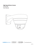
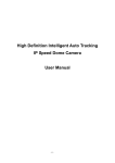
Introduction
Congratulations on the purchase of your new CE-PTZ-KEY. This device is a multifunctional, programmable keyboard controller for Pan-Tilt-Zoom devices, DVRs, and
Matrix devices, and can be programmed with individual protocol settings for each
connected device. It is equipped with a 3-Axis joystick for performing Pan, Tilt, and
Zoom with a single hand.
Main Features:
• Manage up to 9999 devices
• Controls PTZ, DVR, and Matrix in different protocol with pre-programmed settings
• 3-Axis joystick
• Multiplexer operation with DVR and PTZ
• Password-protected for administrative access
• Supports major telemetric protocols
• Dual serial interface with RS232 and RS485
• Supports major DVR brands
• Aluminum construction
• Ergonomic Design
2
S
/
NEXT
/
NEAR.F
PIC
E/
TELDn
Pg
/
ALM
N
MO
GRP/
CAM
1
6
SE
2
HOLD
7
R
ENTE
Power
5
PAN/
AUTO
+
RS485
+
DC12V
+
DC12V T
RS232
RJ45
3
/
MUX
Tx
FAR/.L
PIC
Keyboard
Adaptor
5)
(No: 1437
RS-232/
Power
R T
R
RS2322 GGND GND
RS23 DC12V RS485
/
WIDE
PgUp
SYS
ZOOM
/
NEAR.F
PIC
/
TELE
PgDn
l Outle
ly to Wal
pp
Power Su
CE-PTZ-KEY
Keyboard
t
RS-485/
DC12V
RS-485/
ptor
rd Ada
5)
Keyboa
(No: 1437
DC12V
R
RS2322 G
RS23 DC12V RS485
Rx
S
Power Su
R
FOCU
t
all Outle
pply to W
DVR
R
E/
CLOSL
DE
ENTE
CLR
IRIS
CAM
/
OPEN
BACK
MON
9
-PTZKE
POWE
NEXT
Keyboard
6
RS-232/R T
GND GND
daptoY)r
board A
CE
ded with
RS-485/
ptor
rd Ada
5)
Keyboa
(No: 1437
DC12V
0
ble
RJ45 Ca
/
PREV
0
*
8
r
Monito
Keyboard
/
SHOT
R
RS2322 G
RS23 DC12V RS485
ON/
/
*
7
RJ45
U
OFF/
9
8
MEN
RUN/
4
CLR
4
MUX
AUX/
3
5
01> rd
34< boa
VERm Key
te
Sys
T/
SE/
CLO L
DE
2
Power
ZOOM
FOCU
IRIS
DVR
HOLD
1
+
RS485
+
DC12V
+
DC12V T
RS232
Power
/
RUN/
r
375
AUTO
/
AUX/
le
RJ45 Cab
PAN/
PREV
/
WIDE
PgUp
/
FAR .L
PIC
/
OPEN
BACK
l Outlet
OFF/
ALM/
SYS
MUX
DVR
SE
ON/
GRP/
Tx
Rx
R
POWE
/
SHOT
l Outlet
MENU
MUX
al
pply to W
Power Su
al
pply to W
Power Su
DVR
1437
RS-232/R T
GND
tor
Adap
)
R
DVR
pto
d Ada
5)
RJ45
rd
Keyboa
RECORDE
5/
>
4<01 oard
VER3 Keyb
em
Syst
T/
R
RS2322 G
RS23 DC12V RS485
R
RS232 G
RS232 DC12V RS485
+
RS485
+
DC12V
+
DC12V T
RS232
ed with
-232/ T
ND R
daptor)
oard ACEPTZKEY
VIDEO
DVR
DIGITAL
PACKAGE CONTENTS
+
RS485
+
DC12V
+
DC12V T
RS232
RS-232/R T
GND GND
Power
+
RS485
+
DC12V
+
DC12V T
RS232
RJ45
Keyboard
RJ45
Keyboard
RJ-45
Keyboard
Cable
RS485 Plug (2-pin)
Keyboard
Adaptor
R
RS2322 G
RS23 DC12V RS485
RS-485/
ptor
rd Ada
5)
Keyboa
(No: 1437
DC12V
Power
+
RS485
+
DC12V
+
DC12V T
RS232
RJ45
Keyboard
RS232 Plug (4-pin)
GND
RS-232/R T
GND
AU-P12H
AC-DC Power
Supply
/
SHOT
AUTO
/
NEXT
PREV
/
SE/
CLO L
DE
HOLD
E/
TELDn
Pg
Tx
>
4<01 oard
VER3 Keyb
em
Syst
T/
N
3
1
6
CLR
5
4
Power
> rd
R
4<01 oaDV
VER3 Keyb
em
Syst
T/
CAM
2
ptor
rd Ada
5)
Keyboa
(No: 1437
/
NEAR.F
PIC
MO
AUX/
RS-485/
ZOOM
S
FOCU
IRIS
/
RUN/
/
WIDE
PgUp
/
FAR .L
PIC
/
OPEN
BACK
PAN/
ON/
ALM/
Installation and Set up
SYS
MUX
DVR
OFF/
GRP/
Rx
R
POWE
SE
MENU
MUX
DVR
R
RS2322 G
RS23 DC12V RS485
User Manual
Tx
>
4<01 oard
VER3 Keyb
em
Syst
T/
9
8
R
ENTE
DVR
7
RS-232/R T
GND GND
+
RS485
+
DC12V
+
DC12V T
RS232
ALM/
0
Keyboard
*
RS-485/
RECORDER
DVR
(No: 1437
RS-232/
Power
R T
R
RS2322 GGND GND
RS23 DC12V RS485
RS-485/
ptor
rd Ada
5)
Keyboa
(No: 1437
DC12V
RS-232/R T
GND GND
RUN/
+
RS485
+
DC12V
+
DC12V T
RS232
4
RS-232/R T
GND GND
onitor
pp
Sued
erud
wcl
Po(in
VR or M
BNC to D
VR or
BNC to D
onitor
VR or M
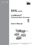
Dimensions
E/
Rx TELDn
Pg
+
RS485
+
DC12V
+
DC12V T
RS232
VIDEO
S
2-5/8”
MUX
DVR
/
N/
OPECK
BA
AUTO
PRE
/
/
RUN
/
AUX
NEX
V/
(included
N
MO
3EN
CAM
6
5
CLR
9
R
ENTE
7
0
*
ble
RJ45 Ca to Wall Outlet
pply
Power Su
t
all Outle
pply to W
Power Su
t
le
t
ut
le
O
l
al
Out
tol W
Wal
to ly
ly pp
ppSu
wer
PoSu
Power
l Outlet
Wal
Supply to
Power it
or
Mon
r
Monito
r
Monito
DVR
RECORDER
VIDEO
DVR
RECORDER
VIDEO
r
Monito
DVR
DVR
RECORDER
M
ZOO
DVR
SE/
CLOEL
D
R/
NEAC.F
PI
/
TELE
n
PgD
DIGITAL
VIDEO
RECORDER
DVR
N
MO
3
CAM
2
1
6
CLR
5
4
8”
0
KESu
wer
PoTZ
with CE-P
DIGITAL
T/
HOLD
E/
TELDn
Pg
/
NEAR.F
PIC
FOC
IRIS
G
/
ALM
ZOOM
R
ENTE
SE/
CLO L
DE
TER
0
Keyboard
DVR
US
S
FOCU
IRIS
NEXT
8
DIGITAL
/
PAN
ON/
/
OFF
RP/
CLR
daptoY)r pply to Wall Outlet
board A
Key
E/
WIDUp
Pg
FAR/.L
PIC
/
WIDE
PgUp
/
FAR .L
PIC
CLR
*
RJ45
SYS
MUX
DVR
T/
SHO
SET
U
MEN
Rx
ER
POW
PREV
4
Tx
01> rd
34< boa
VERm Key
e
yst
CA
9
2
Power
SYS
MUX M
/
OPEN
BACK
AUTO
CAM
8
Tx
/
8
1
R
RS2322 G
RS23 DC12V RS485
6
/
*
onitor
DVR
DIGITAL
6
7
Monitor
BNC to D
ON/
/
HOLD
9
RUN/
AUX/
Keyboard
RS-485/
/
SHOT
N
5
7
5
RJ45
ptor
rd Ada
5)
Keyboa
(No: 1437
VR or M
RJ45
Keyboard
OFF/
GRP/
ALM/
3
R AR/
POWE NE
PIC.F
SE/
CLO L
DE
DVR
2
MO
E/
TELDn
Pg
/
NEAR.F
PIC
N
MO
PAN/
4
2
1
+
RS485
+
DC12V
+
DC12V T
RS232
SE
MENU
3
MUX
DVR
Power
Ke
CE-PTZ
ed withtor
(includ
p
rd Adal TZ
t
leY)
KE
ut
O
Keyboawlyith
-P
al
W
to CE
DC12V
BNC to D
R
RS2322 G
RS23 DC12V RS485
r
Adapto
Keyboard 5)
DC12V
VIDEO
FO
IRIS
XT/
> NE
rd
4<01
EV/ oa
KePRyb
VER3
LD/
HOem
1
Syst
T/
GRP/
RJ45
AUX/
DVR
SE/
CLO L
DE
ZOOM
r
Unpacking
your
keyboard
Monito
ble
RJ45 Ca
Your keyboard comes with a power supply, as well
as
a
keyboard
adaptor, and connecting
r
AdaptoY)
eyboawrd
K
-PTZKE
CE
e firm surface.
ith
plugs, and cable. Carefully remove the contents
from its packing and setRJon
45 Cabla
(included
t
le
ut
r ble needs.
Wall O
Save the packing in case of future service requirements
or
transportation
RJ45 Ca
pply to
Adapto
Power Su
KEY)
yboard
DC12V
DIGITAL
/
CUS
AUX/
OFF/
IRIS
/
WIDE
PgUp
HOLD
ZOOM
S
FOCU
NEXT
/
PREV
/
/
WIDE
PgUp
N/
TOPASYS
/
FAR .L
PIC
/
OPEN
BACK
SYS
/
FAR .L
PIC
/
OPEN
BACK
XAU
ON/ MU
DVR
OFF/
PAN/
AUTO N/
RU
ON/
Rx
R
MUX
DVR
Tx
POWE
/
OTP/
SHGR
SE M/
AL
MENU
MUX
MUX
Rx
R
POWE
/
SHOT
SE
MENU
9
8
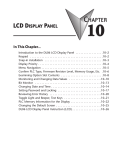
LCD Display
with backlight
ER
ENT
7
0
*
01> rd
34< boa
VER m Key
te
Sys
T/
SE
ENU
8-1/4”
DVR
M
MUX
DVR
ER
POW
T/
SHO
/
PAN
ON/
AUTO
/
OFF
/
GRP
/
ALM
/
RUN
/
AUX
Operation Keys
PRE
/
NEX
V/
T/
HOLD
MO
3
2
1
6
5
Extended Function Keys
4
9
8
7
0
*
Digit Pad
3
Precautions
For all service or installation needs, please refer to qualified service personnel or system installers
Do not attempt to disassemble the device
To prevent electric shock, do not remove screws or cover. There are no user-serviceable parts inside.
Contact qualified service personnel for maintenance
Handle the device with care
Do not strike or shake, as this may damage the device. It should be protected against extreme pressure,
vibration, and humidity during transportation and storage. Damages caused by improper transportation
may void the warranty.
Do not operate the device beyond its specified temperature, humidity, or power source ratings.
Do not use the dome camera in an extreme environment where high temperature or high humidity
exists.
Do not install this product in a flammable and explosive environment.
Make sure that the installation is done according to your local electricity and safety regulations.
Before installation or maintenance, make sure the device is disconnected from the power source.
Do not use any power source other than 12vdc in order to prevent damages to this device.
For details, please refer to the “Specifications” section for further details.
Handle the device during the installation carefully.
Falls, or extreme vibration may cause irreparable damages and void the warranty.
Do not install or operate the device near any high voltage devices or high voltage cable.
The safety distance should remain at least 50m.
This product should be operated indoor only.
4
WARNING
TO REDUCE THE RISK OF ELECTRIC SHOCK OR FIRE, SO NOT EXPOSE THIS PRODUCT TO RAIN
OR MOISTURE. DO NOT INSERT ANY METALLIC OBJECTS THROUGH THE VENTILATION GRILLS
OR OTHER OPENINGS ON THE EQUIPMENT.
This symbol indicates that dangerous voltage
constituting a risk of electric shock is present
within this unit.
This symbol indicates that there are important
operating and maintenance instructions in the
literature accompanying this unit.
FCC COMPLIANCE STATEMENT
FCC INFORMATION: THIS EQUIPMENT HAS BEEN TESTED AND FOUND TO COMPLY WITH
THE LIMITS FOR A CLASS A DIGITAL DEVICE, PURSUANT TO PART 15 OF THE FCC RULES.
THESE LIMITS ARE DESIGNED TO PROVIDE REASONABLE PROTECTION AGAINST HARMFUL
INTERFERENCE WHEN THE EQUIPMENT IS OPERATED IN A COMMERCIAL ENVIRONMENT.
THIS EQUIPMENT GENERATES, USES, AND CAN RADIATE RADIO FREQUENCY ENERGY AND, IF
NOT INSTALLED AND USED IN ACCORDANCE WITH THE INSTRUCTION MANUAL MAY CAUSE
HARMFUL INTERFERENCE TO RADIO COMMUNICATIONS. OPERATION OF THIS EQUIPMENT
IN A RESIDENTIAL AREA IS LIKELY TO CAUSE HARMFUL INTERFERENCE IN WHICH CASE THE
USER WILL BE REQUIRED TO CORRECT THE INTERFERENCE AT HIS OWN EXPENSE.
CAUTION: CHANGES OR MODIFICATIONS NOT EXPRESSLY APPROVED BY THE PARTY
RESPONSIBLE FOR COMPLIANCE COULD VOID THE USERS AUTHORITY TO OPERATE THE
EQUIPMENT.
CE COMPLIANCE STATEMENT
WARNING: THIS IS A CLASS A PRODUCT. IN A DOMESTIC ENVIRONMENT, THIS PRODUCT
MAY CAUSE RADIO INTERFERENCE IN WHICH CASE THE USER MAY BE REQUIRED TO TAKE
ADEQUATE MEASURES.
CAUTION: BEFORE ATTEMPTING TO CONNECT OR OPERATE THIS PRODUCT, PLEASE READ THE
LABEL ON THE BOTTOM AND USER’S MANUAL CAREFULLY.
Technical specifications are subject to change without prior notice. Manual may contain
mistakes or print errors. All trademarks mentioned belong to their respective owners.
5
Installation
Safety Instructions before starting
- Do not install and operate this appliance in a flammable and explosive environment.
- Make sure that the installation is done according to the local electricity safety regulations of your country.
- Before installation and maintenance, make sure that the appliance is disconnected from the power source.
- Handle the device during installation carefully. Falls or extreme vibration may cause irreparable damages or void the warranty.
- Do not install or operate the device near any high-voltage devices or high-voltage cable. The safety distance should remain at least 50m.
- To achieve best image quality, its recommended to use underground cable shielded with steel tube. Do not install the cable without any protection.
- In a thunderstorm area or region with high inductive voltage, such as high voltage transformer stations, it is necessary to use additional lightning-proof equipment or
lightning rod for protection.
- For outdoor installation, lightning-proof and grounding of the device should be considered. Please refer to the industrial safety regulations of your country.
- Grounding should be considered to eliminate any interference and fulfill the safety requirements. Do not connect the ground with short-circuited or other high voltage electric networks.
- Make sure that the installation environment meets the requirements of the device, such as weight support, sufficient room for cords, and power supply requirements.
6
Installation
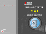
Connection Schematic
The keyboard can be connected to various PTZ cameras, DVRs, and Matrix devices through the
keyboard adaptor. All accessories are tested for maximum compatibility and best performance.
For the first start, please ensure your keyboard parameters match
those shown on the initial screen (ie.
protocol, baud-rate, ID). Doing so will
allow you to enter the OSD for further
settings.
321
era
PTZ Cam
Tx
>
4<01 oard
VER3 Keyb
em
Syst
T/
)
lack Wire
AC24V (B
ed Wire)
AC24V (R
DVR
ection
BNC Conn DVR
r or
to Monito
MENU
MUX
PA
AUTO
S
/
NEXT
PREV
/
HOLD
SE/
CLO L
DE
R
RS2322 G
RS23 DC12V RS485
Adaptor
rd 5)
Keyboa
(No: 1437
RS-232/R T
GND GND
+
RS485
+
DC12V
+
DC12V T
RS232
CAM
2
6
CLR
4
Power
9
8
R
ENTE
7
RJ45
0
Keyboard
*
ble
EY
CE-PTZK
RJ45 Ca
daptoY)r
board A
Key
(included
E/
TELDn
Pg
N
3
5
RS-485/
/
NEAR.F
PIC
MO
AUX/
1
DC12V
ZOOM
FOCU
IRIS
/
RUN/
/
WIDE
PgUp
/
FAR .L
PIC
/
OPEN
BACK
N/
ON/
ALM/
SYS
MUX
DVR
OFF/
GRP/
ire)
(Green W )
RS485+
Wire
(Yellow
RS485-
Rx
R
POWE
/
SHOT
SE
TZKE
with CE-P
l Outlet
ly to Wal
pp
Power Su
VR or M
BNC to D
onitor
l Outlet
ly to Wal
pp
Power Su
r
Monito
DVR
DVR
DIGITAL
VIDEO
RECORDER
RS485 CableThe telemetric control of the device uses RS485 serial communication with half duplex
transmission technology. The transmission distance can vary, depending on cable type,
and baud rate. The following table shows maximum distances based on cable with 0,56mm
(24AWG) twisted pair:
Baud Rate
2400 bps
4800 bps
9600 bps
19200 bps
Max. Distance
5577ft / 1700m
3609ft / 1100m
2297ft / 700m
1312ft / 400m
Due to environmental interfaces, such as electromagnetic and induction fields, or number of connected
devices on the RS485 bus, or using thinner than 24AWG cable, the transmission range may be less.
7
Installation
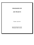
Star-ConnectionThe star-form connection is most commonly used. It enables the connection of different dome
cameras with longer cable runs. It is recommended to use an RS485 distributor to ensure the
telemetric data transmission.
RS 485+
RS 485-
Tx
>
4<01 oard
VER3 Keyb
em
Syst
Rx
ER
SYS
POW
The advantage of the star-connection is that every channel can work independently and can
take a cable length up to 3,280 feet (1000 meters) (depending on cable quality). In cases where
more dome cameras are installed, the star-connection can be extended with additional RS485
distributors.
/
WIDE
PgUp
FAR/
PIC.L
/
OPEN
BACK
N/
ON/
OPA
AUT
S
ZOOM
FOCU
IRIS
OFF/
/
GRP
/
MUX
DVR
T/
SHO
SET/
U
MEN
MUX
DVR
NEX
/
ALM
D/
/
E/
CLOS
DEL
HOL
RUN
/
T/
PREV
/
NEAR
PIC.F
/
TELE
PgDn
MON
AUX
3
2
CAM
1
6
5
CLR
4
9
8
R
ENTE
7
0
*
Termination ON
Termination ON
Termination OFF
Termination OFF
Tx
>
4<01 oard
VER3 Keyb
em
Syst
U
SYS
MUX
FAR/
PIC.L
/
OPEN
BACK
OPA
AUT
RS 485+
/
WIDE
PgUp
DVR
N/
ON/
S
ZOOM
FOCU
IRIS
OFF/
/
GRP
/
Rx
ER
POW
T/
SHO
SET/
MEN
MUX
DVR
NEX
/
ALM
HOL
RUN
/
E/
CLOS
DEL
PREV
D/
/
T/
/
NEAR
PIC.F
/
TELE
PgDn
RS-485 Distributor
MON
AUX
3
2
RS 485+
RS 485-
CAM
1
6
5
CLR
4
9
8
R
ENTE
7
RS 485-
0
*
Tx
>
4<01 oard
VER3 Keyb
em
Syst
FOCU
U
ER
Tx
Rx
POW
HOL
MUX
ZOOM
OPEN
BACK
3
TELE/
PgDn
PIC.L
/
SET/
/
NEAR
PIC.F
/
WIDE
PgUp
MON FAR/
MEN
PAN/
2
SYS CLOSE/
DEL
DVR
T/
SHO
MUX
S
IRIS
NEXT
/
PREV
D/
/
WIDE
PgUp
FAR/
PIC.L
/
OPEN
BACK
/
>
4<01 oard
VER3 Keyb
/
em
RUN
/
Syst
AUX
ALM
Monitor
(optional)
SYS
MUX
DVR
PAN/
AUTO
ON/
OFF/
GRP/
/
Rx
ER
POW
T/
SHO
SET/
U
MEN
MUX
DVR
CAM FOCUS
ZOOM
Up to 750m, coaxial cable
Video CableVideo Amplifier (optional)
Coaxial cable with 75Ω impedance with copper conductor at center conductor, and shielded
with 95% copper. The following table shows different cable type and its maximum length:
DVR
1
OFF/
/
/
4 D/
HOL
CLR NEAR
PIC.F
9
RUN
8
AUX
/
NEXT
5
/
PREV
ALM
/
Termination ON
CLR
Cable Standard
RG 11 / U
Termination ON
DVR
750 ft / 229m
Balun Transmitter
1000 ft /
(optional)
Termination ON
0
*
The values are for reference only. Depends on the cable
quality and environmental conditions, the transmission
Balun Receiver
distance
might be less.
(optional)
DIGITAL
RG 6 / U
ENTE
7
DVR
(optional)
Max. Distance (m / ft)
RG 59 / U
R
Termination OFF
Termination OFF
ENTE
CAM
9
8
Termination OFF
R
MON
0
6
*
5
4
Termination OFF
TELE/
PgDn
E/
CLOS
DEL
3
7
2
1
Termination ON
IRIS
6
GRP/
/
AUTO
ON/
305m
VIDEO
RECORDER
Monitor
(optional)
1500 ftUp/ to
457m
1200m, twisted pair or cat5 cable
If the cable length is more than 1,312ft (400m), it is recommended to use optional accessories,
RS-485 Distributor
such as a video amplifier or twisted-pair video converter,
for boosting the video signal.
RS-485 Distributor
Tx
>
4<01 oard
VER3 Keyb
em
Syst
120Ω
Resistor
U
PAN/
CAM FOCUS
AUTO
/
4 D/
HOL
CLR NEAR
PIC.F
9
RUN
8
AUX
/
NEXT
5
/
PREV
RS 485+
TELE/
PgDn
120Ω
Resistor
ZOOM
RS 485-
IRIS
6
GRP/
ALM
/
OPEN
BACK
3
/
NEAR
PIC.F
/
WIDE
PgUp
PIC.L
/
SET/
2
/
MUX
MON FAR/
MEN
ON/
SYS CLOSE/
DEL
DVR
T/
SHO
1
OFF/
Tx
Rx
POW
HOL
MUX
DVR
ZOOM
S
FOCU
IRIS
ER
PREV
D/
/
WIDE
PgUp
FAR/
PIC.L
/
OPEN
BACK
/
NEXT
/
ALM
/
SYS
MUX
DVR
PAN/
AUTO
ON/
OFF/
GRP/
>
4<01 oard
VER3 Keyb
/
em
RUN
/
Syst
AUX
/
Rx
ER
POW
T/
SHO
SET/
U
MEN
MUX
DVR
TELE/
PgDn
E/
CLOS
DEL
R
MON
ENTE
3
7
2
DVR
(optional)
CAM
0
1
6
*
5
CLR
4
9
8
R
ENTE
7
0
DVR
*
DIGITAL
Device 1
Device 2
VIDEO
RECORDER
Device 3
Monitor
(optional)
Up to 750m, coaxial cable
Extend connection distance
with video amplifier
Up to 750m, coaxial cable
Monitor
(optional)
Video Amplifier (optional)
Video Amplifier (optional)
>
4<01 oard
VER3 Keyb
em
Syst
RS485 Connection
>
4<01 oard
VER3 Keyb
em
Syst
RS485 Connection
CE-PTZ-KEY
CE-PTZ-KEY
DVR
(optional)
DVR
(optional)
DVR
DIGITAL
VIDEO
RECORDER
DVR
DIGITAL
Balun Transmitter
Balun Receiver
(optional)
(optional)
Balun Transmitter
Balun Receiver
(optional) Up to 1200m, twisted pair or cat5 cable (optional)
Extend connection distance with
Twisted-Pair video converter
VIDEO
RECORDER
Monitor
(optional)
Monitor
(optional)
Up to 1200m, twisted pair or cat5 cable
>
4<01 oard
VER3 Keyb
em
Syst
RS485 Connection
>
4<01 oard
VER3 Keyb
em
Syst
RS485 Connection
CE-PTZ-KEY
CE-PTZ-KEY
DVR
(optional)
DVR
(optional)
DVR
DIGITAL
DIGITAL
8
VIDEO
DVR
VIDEO
RECORDER
RECORDER
Tx
SYS
UX
E/
WIDUp
Pg
FAR/.L
PIC
M
ZOO
US
FOC
RIS
R/
NEAC.F
PI
SE/
CLOEL
D
/
TELE
n
PgD
Installation
Key Description
CLR
LCD Display
with backlight
ER
ENT
1. Camera Operation Keys
Tx
01> rd
34< boa
VER m Key
te
Sys
8-1/4”
MUX
DVR
/
/
GRP
PRE
/
2. Operation Keys
/
TELE
n
PgD
R/
NEAC.F
PI
SE/
CLOEL
D
N
MO
3
CAM
2
1
3.
T/
HOLD
/
RUN
/
AUX
NEX
V/
ZOO
US
FOC
IRIS
OFF
ALM
3-Axis Joystick
M
/
PAN
AUTO
ON/
/
/
E/
WIDUp
Pg
FAR/.L
PIC
N/
OPECK
BA
5.
SYS
MUX
DVR
T/
SHO
SET
U
MEN
Rx
ER
POW
6
CLR
5
Extended Function Keys
4
9
8
ER
ENT
7
0
*
4. Digit Pad
ION
ZOOM
1. Camera Operation Keys:
Zoom WIDE / TELE: Zoom-in and zoom-out
FOCUS FAR / NEAR: Manual focus
2-5/8”
2-5/8”
01> rd
34<eyboa
IRIS OPEN / CLOSE:
iris
K
VERm Manual
te
S
Tx
Tx
SYS
M
US
Sys
ZOO
/
SET
U
MEN
MUX
N/
OPECK
BA
/
PAN
ON/
AUTO
/
/
ALM
PRE
LD/
/
RUN
/
AUX
T
NEX
V/
HO
MO
3
3
CAM
CAM
2
6
6
5
5
CLR
4
4
/
TELE
n
PgD
R/
NEAC.F
PI
SE/
CLOEL
D
N
MO
N
1
1
E/
TEL
E/ Dn
/ TEL Pg
NEAR PgDn
AR/PIC.F
OSE/ NE .F
CL
E/ L PIC
CLOSL DE
DE
XT/
NE
XT/
EV/ NE
PR
EV/
LD/ PR
HO/
HOLD
2
M
ZOO
FOC
IRIS
OFF
GRP
OF
OFF/
RUN/
RUN/
AUX/
AUX/
US
/
/
TELE
n
PgD
E/
WIDUp
Pg
FAR/.L
PIC
GRP/
GRP/
ALM/
ALM/
2. Operation Keys:
DVR: Enter the DVR control mode 8”8”
MUX: Multiplexer mode LEFT: WIDE
RIGHT
MENU: Enter setup menu or PTZ mode
SET: Set preset position
SHOT: Recall preset position
/
R/
NEAC.F
PI
T
SHO
MUX
MUX
DVR
DVR
SYS
MUX
DVR
/
DVR
FOC
SE/
CLOEL
D
ER
UP
E/
WIDUp
Pg
/
.L
T
Rx
ER
POW
4. Digit Pad:
0-9: Digit input from 0 to 9
*: Star Key
MON: Monitor switch
CAM: Camera switch
RIGHTCLR:
: TELE
Clear and Cancel
ENTER: Enter key
Tx
Tx
Rx
R Rx
SYS
PORWE
S
MUX SY
POWE
X
DE/
DVR MU
WI
/PgUp
DVR
/
WIDE
Up
FAR/
SH/ OT
R/ .L Pg
SHOT
EN/ FA .LPIC
OP
SE
/ CK PIC
T/
BA
OPEN
SE
NU
CK
ME
BA
ZOOM
MENU
PAN/
SZOOM
TO
N/
AU
PA
FOCU
CUS
ON/ AUTO
IRIS FO
ON/
F/
IRIS
01> rd
340<1> borad
VE3R4< Kebyoa
VEsRtmemKey
ye
ySst
T/
CLR
9
9
8
8
0
0
*
*
LCDDisplay
Display
LCD
withbacklight
backlight
with
TER
EN
R
ENTE
7
7
01> rd
340<1> borad
VE3R4< Kebyoa
VERtemKey
Sytsem
Sys
SET/
N
MO
3
8-1/4”
8-1/4”
CLR
5
DOWN3. Extended Function Keys:
ALM: Alarm function
GRP: Tour function
OFF: Function off
ON: Function on
AUTOPAN: Auto pan function
AUX: Auxiliary function
RUN: Function start
HOLD: Hold
PREV: Previous device
NEXT: Next device
ER
ENT
IRIS
HO/
HOLD
MO
3
3
CAM
CAM
2
2
6
6
5
5
CLR
4
4
E/
TEL
E/ Dn
/ TEL Pg
NEAR PgDn
AR/PIC.F
OSE/ NE .F
CL
E/ L PIC
CLOSL DE
DE
N
MO
N
1
ExtendedFunction
FunctionKeys
Keys
Extended
3-AxisJoystick
Joystick
3-Axis
ZOOM
OM
CUSZO
FO
S
FOCU
IRIS
XT/
NE
XT/
EV/ NE
PR
EV/
LD/ PR
RUN/
RUN/
1
7
9
8
7
8
TER
EN
R
ENTE
0
0
*
*
*
CLR
9
7
0
DigitPad
Pad
Digit
Joystick Functions
Navigation
Zoom
ZOOM
ZOOM
NAVIGATION
NAVIGATION
01> rd
340<1> borad
VE3R4< Kebyoa
VEsRtmemKey
ye
ySst
S
DVR
DVR
MENU SE
MENU
MUX
MUX
ALM/
ALM/
SH/
SHOT
PAN/
TO
N/
AUPA
ON/ AUTO
ON/
IRIS
N
MO
N
6
5
CLR
9
7
RIGHT
RIGHT
CLR
9
8
R
ENTE
TER
NE
XT/
EV/ NE
HO/
HOLD
N
MO
N
CAM
CAM
2
1
6
5
DOWN
DOWN
4
CLR
4
9
8
7
8
0
TELE
TELE
*
CLR
9
TER
EN
R
ENTE
7
*
*
6
5
0
0
MO
3
3
1
E/
TEL
E/ Dn
/ TEL Pg
NEAR PgDn
AR/PIC.F
OSE/ NE .F
CL
E/ L PIC
CLOSL DE
DE
XT/
LEFT:WIDE
WIDE
LEFT:
PR
EV/
LD/ PR
RUN/
RUN/
AUX/
AUX/
/
SH/ OT
SHOT
EN
7
*
9
OFF/
OFF/
GRP/
GRP/
2
LEFT
LEFT
6
5
4
8
MUX
MUX
ALM/
ALM/
CAM
CAM
1
4
DVR
DVR
MENU SE
MENU
MO
3
3
2
2
UP
UP
ZOOM
OM
E/
TEL
E/ Dn
/ TEL Pg
NEAR PgDn
AR/PIC.F
OSE/ NE .F
CL
E/ L PIC
CLOSL DE
DE
NE/
/ NEXT
HO/
HOLD
FO
S
FOCU
Tx
Tx
Rx
R Rx
SYS
PORWE
S
MUX SY
POWE
X
DE/
DVR MU
WI
/PgUp
DVR
WIDE
Up
FAR/
R/ .L Pg
EN/ FA .LPIC
OP
/ CK PIC
BA
OPEN
CK
BA
ZOOM
PAN/
SZOOM
TO
N/
AU
PA
FOCU
CUS
ON/ AUTO
IRIS FO
ON/
IRIS
01> rd
340<1> borad
VE3R4< Kebyoa
VERtemKey
Sytsem
Sys
SET/
T/
CUSZO
IRIS
XT/
PREV
EV/
LD/ PR
RUN/
RUN/
AUX/
AUX/
Tx
Tx
Rx
R Rx
SYS
PORWE
S
MUX SY
POWE
X
DE/
DVR MU
WI
/PgUp
DVR
WIDE
Up
FAR/
R/ .L Pg
EN/ FA .LPIC
OP
PIC
/
CK
BA
OPEN
BACK
OT/
SET/
T/
OFF/
OFF/
GRP/
GRP/
1
TELE
SYS
DVR
PAN/
TO
N/
AUPA
ON/ AUTO
ON/
OFF/
OFF/
GRP/
GRP/
AUX/
AUX/
OperationKeys
Keys
Operation
9
8
DVR
DVR
ALM/
ALM/
6
4
Tx
Tx
Rx
S
MUX SY
X
DE/
DVR MU
WI
/PgUp
WIDE
Up
FAR/
R/ .L Pg
EN/ FA .LPIC
OP
/ CK PIC
BA
OPEN
BACK
PO
OT/
SH/
SHOT
T/
Rx
5. 3-Axis PTZ Joystick:
LEFT / RIGHT: Pan movement
UP / DOWN: Tilt movement
TURN: Zoom in / out
CAM
2
1
MENU SE
MENU
MUX
MUX
CameraOperation
OperationKeys
Keys
Camera
R
POWE
WER
0
RIGHT: :TELE
TELE
RIGHT
Operation
VERxx<01>
System Keyboard
SET MUX PROTOCOL
>ROBOT
VERxx<01>
VERxx<01>
SETThe
MUX PROTOCOL
SET MUX PROTOCOL
Initial SetupAfter power up, the keyboard
will
start
the
initialization
and
self-test.
LCD
MON--CAM- ALMpress
menu
key
to
exit
startup
screen
System Keyboard
VERxx<01>
>ROBOT System Keyboard
SET
MUX PROTOCOL
001
0001 >ROBOT
0001
MON
display will show initial
startup
screen. Press MENU to start
using
the
keyboard.
SET MTX BAUD RAT
VERxx<01>
System
SETKeyboard
MUX PROTOCOL
>ROBOT
MON--CAMALM001
press menu key to exitMON--startupCAMscreenALMpressSystem
menu Keyboard
key to exit startup screen
>9600bps
>ROBOT
VERxx<01>
001
0001
SETtoMUX
PROTOCOL
CAM+#
SET+#
S
001
0001 0001
MON--CAM-0001
ALMpress menu key
exit
startup
screen
SET MTX BAUD
RAT
SET
MTX
BAUD
RAT
System
Keyboard
>ROBOT MON--- CAM- ALM001
0001
0001
MON--ALM- screen
001
0001
0001
0
CAM
001
0001
0001
Startup
Screen
press menu
key toCAMexit startup
Main Operation Screen:
>9600bps
>9600bps
SET MTX BAUD RAT
001
0001 0001
CAM+#
001
0001 0001
SET+#SET DVR :
SHO
001
MON--SETCAMMTX ALMBAUD RAT Selected Selected Selected
>9600bps
press menu key to exit startup screen
001Seq 0001
0001 Ti
MON--- CAM- ALM001 >SET_PROTOCOL>
0001 0001
001
001 >9600bps
0001 0001
Camera
SH
Alarm CAM+#
Input Pos SpdSET
DVR : SET+#
SET
RAT Monitor
SETMTX
DVRBAUD
:
001
0001
0001
001
000
000
000
Selected Selected Selected
Seq
Selected
Selected
001
0001
0001
MON--- CAMALM- Selected
001
0001
0001
00
>SET_PROTOCOL>
>9600bps
>SET_PROTOCOL>
SET DVR
Camera
Seq
Pos : Spd Ti
MonitorSelected
001
Camera
SET DVR :
Monitor
Alarm Input
001
0001
0001 Alarm Input
SelectedSETSelected
DVR :
>SET_PROTOCOL>
001
000
>SET_BAUDRATE>
Selected Selected Selected
M
Camera
Monitor >SET_PROTOCOL>
Alarm Input CAM+1
DVR_ID:01
Seq
Pos 000
Spd000
Ti
SET
DVR
: :
001
0001 0001
SET
DVR
Camera
Monitor
Alarm
Input
001 000 000 SET
000DVR :
DVR_
Selected Selected Selected
>SET_PROTOCOL>
CAM+1 use your connected PTZ camera,
>SET_BAUDRATE>
To quickly
youCAM+1
may have
to type in the corresponding
camera ID
>SET_BAUDRATE>
SET DVR :
MUX
DVR_ID:01
ALL : >NVIDO
Monitor Camera
Alarm Input
0001camera
0001 info will show up on >SET_BAUDRATE>
001
0001 0001
CAM+1
SET DVR : 001
01 : >NVIDO
screen
afterCAM
its connected
(even
if
it
already
shows
the
correct
ID).
(ID#01
is
default)
Press
1
ENTER
MU
M
DVR_ID:01
DVR_ID:01
IN:01
CAM+1
001 >SET_BAUDRATE>
0001
0001
ALL : >NVIDO
camera
info willtype
showinup
ALL
: >NVIDO
SET
DVR
:
camera info will show up on
theoncamera number PTZ
P
Cam:001
DVR_
001
0001
0001
01 : >NVIDO
CAM+1
after
01
: >NVIDO
>SET_BAUDRATE>
screen
after its connected
you wish to control: example:
ALL : >NVIDO IN:01
camera info
will screen
show
up
on its connected
MU
DVR_ID:01
ALL : >9600bps PTZ
001info
0001
0001
type in the camera
number
ALLits: >NVIDO
type
in the
camera
number
hit “CAM”
button, then “1”, PTZ
camera
will
show
up
on
01 : >NVIDO
screen after
connected
PTZ
Cam:001
01 : >9600bps
M
Set
DVR_ID:01
younumber
wish to control:
01ALL
: >NVIDO
you after
wish
towill
control:
thenexample:
“ENTER” to control camera
#1. DVR ID: IN:01
screen
connected
type in the
camera
ALL
:
>9600bps
: >NVIDO
ALL
: >9600bps
camera
infoits
show example:
up on
PTD
01<
00
99>
PTZ
Cam:001
Set
hit “CAM”
button,
then
“1”,be necessary the first
hitin“CAM”
button,
then “1”,
This
may
type
the
camera
number
you wish to
control:
example:
01 : >9600bps
0101
: >NVIDO
: >9600bps
screen
after
its connected
ALLDVR
: >9600bps
Set
Set
ID:
01<
SET DVR :
then
“ENTER”
totime
control
camera
#1.your keyboard,
then
“ENTER”
to
control
camera
#1.
you
connect
you
wish
to
control:
example:
hit
“CAM”
button,
then
“1”,
ALL : >9600bps
type in the camera number
01 00
: >9600bps
>SET_CHANNEL> 01<
Se
This
maycamera
be necessary
the
first “CAM-0001” 01<
DVR
ID 99>
User
Mode
& Admin
Mode
This
may
necessary
even
shows
on
Set
DVR
ID: Output to Matrix
hityou
“CAM”
button,
then
“1”, the first
then “ENTER”
control
#1. if it
01ALL
:to
>9600bps
wish
tobe
control:
example:
SET
DVR
:
:
>9600bps
SET
DVR
:
time you
connect
your
keyboard,
time
you
connect
your
keyboard,
the
LCD
display.
01<
00
99>
then
“ENTER”
to
control
camera
#1.
DVR01
I
This
may
be
necessary
the
first
ID:01
OUT:0001
hit “CAM” button, then “1”,
01
: >9600bps
>SET_CHANNEL>
MUX
The
keyboard
will
enter
USER
MODE
power
allows
performing
PTZ
SET
DVR Output
: CAM:001
even
if keyboard,
it showsafter
“CAM-0001”
on up, which
to >SET_CHANNEL>
Matrix
DVR
ID
even
ifbe
it shows
“CAM-0001”
on#1.automatically
This
may
necessary
thecamera
first
timeinto
you connect
your
IN:01
ID:0
then
“ENTER”
to control
SET DVR
: LCD display.
>SET_CHANNEL>
the
the
LCD
display.
time
you
connect
your keyboard,
ID:0
even if it to
shows
“CAM-0001”
on
ID:01
Outputwill
to Matrix DVR ID
DVR
IDInputOUT:0001
and
DVR
control,
and
keyboard
setup
menu.
Following
message
This
may
be
necessary
the
first restrict user access
MonitorIN:0
IDM
DVR
Assign to show:
ADMIN
AUTHORITY
>SET_CHANNEL>
even
if
it
shows
“CAM-0001”
on
IN:0
the
LCD
display.
SET DVR :
IN:01
Channel CAM:001
Camera
ID
time you connect your keyboard,
ID:01
OUT:0001
DVRID
I
001
0001 0001
the
LCDif display.
>SET_CHANNEL>
DVR
ID
DVR ID
even
it shows
“CAM-0001” on
MUX
IN
Monitor ID for output Chann
Monitor
ID for output
DVR
Input
IN:01
CAM:001
Assign to
ADMIN
AUTHORITY
ADMIN
AUTHORITY
ID:01
OUT:0001
Chan
Channel
Camera
ID ID for output
the LCD
DVR ID
001
0001 PASSWORD
0001
Monitor
001 display.
0001 0001
ADMIN AUTHORITY
IN:01
CAM:0001 MU
DVR Input
Assign to
:
DVR ID
Ch
Monitor
ID
for
output
Channel
Camera
ID
ADMIN AUTHORITY
001
0001
0001
ID:01
OUT:0001
ID:01
OUT:0001
001
0001 : 0001
DVR ID IN:01 PASSWORD
IN:01
CAM:0001
Monitor :ID for**********
output
CAM:0001
ID:01
OUT:0001
PASSWORD
ADMIN
AUTHORITY
DVR CH ID
Camera
ID:01 :
OUT:0001
IN:01
CAM:0001
Enter
Mode:
001 Administrator
0001 0001
PASSWORD
**********PASSWORD :
**********
(mappe
IN:01
CAM:0001
PASSWORD :
9876543210
ID:01
DVR CH ID
DVR
CH ID OUT:0001
**********
Camera ID
Camera
ID
1. Press
ON: &: 2 at the same time
PASSWORD
:
PASSWORD
IN:01
CAM:0001
PASSWORD
**********
(mapped to DVR CH ID)
DVR CH ID
(mapped to DVR CH ID)
Camera ID
9876543210
9876543210
PASSWORD
2. Enter
your password with the number
with ENTER (default password:
9876543210)
DVRkeys
CH ID: and confirm
Camera
ID
(mapped
to
DVR
CH ID)
**********
PASSWORD :
SET
CAM PROTOCOL
9876543210
(mapped
to
DVR CH ID)
DVR CH ID
Camera
ID
9876543210
>SET_PROTOCOL>
PASSWORD :
ALL : >B02
(mappedparameters
to DVR
ID) as described in the
SETnext
CAM PROTOCOL
ALL CH
: >B02
Entering
into Admin. mode will allow you toSET
setCAM
upPROTOCOL
device
steps.
9876543210
01 : >B02
>SET_PROTOCOL>
01 : >B02
>SET_PROTOCOL>
ALL : SET
>B02
SET CAM PROTOCOL
CAM PROTOCOL
3. To exit Admin. mode, the device must beSETpowered
down by
the
RJ45 connector 01
from
ALL unplugging
: >B02
: >B02
CAM PROTOCOL
>SET_PROTOCOL>
>SET_BAUDRATE>
: >B02
>SET_PROTOCOL>
the back of the keyboard.
SET CAM PROTOCOL
ALL : >9600
SET
CAM
PROTOCOL 01ALL
ALL
: >9600bps
: >B02
SET
CAM
PROTOCOL
>SET_BAUDRATE>
>SET_BAUDRATE>
: >9600bps
0101 : >B02
SET CAM PROTOCOL
>SET_PROTOCOL>
ALL : >9600bps 01 : >9600
SET CAM PROTOCOL
ALL : >9600bps
>SET_BAUDRATE>
01 : >9600bps
>SET_BAUDRATE>
SET KEY ID
01ALL: >9600bps
SET CAM PROTOCOL
: >9600bps
Keyboard Setup:
>01<00 -->63>
>SET_BAUDRATE>
01 : >9600bps
After entering Admin. mode, press MENU SET KEY ID
SET KEY LEV
SET KEY ID
SET KEY LEVEL
>01<00 -->1
>01<00
-->63>
>01<00
-->15>
>01<00
-->63>
SET
KEY
LEVEL
SET
KEY
ID
SET MON RANGE
To cycle through selections press UP or DOWN to cycle through settings.
SET KEY LEVEL
SET KEY ID
>01<00
-->15>
>01<00 -->63>
>0000
-->0239
To cycle through options, turn the joystick>01<00
(tele
zoom
or wide
zoom)
to change setting. SET MON RANGE
>01<00
-->15>
-->63>
SET CAM RA
SET
MON
SET
CAM
RANGE
SET
KEY
LEVEL
SET
KEY
ID RANGE
>0000 -->99
>0000-->63>
-->0239
Apply a selection by pressing ENTER
>0000-->15>
-->9999
>01<00
>01<00
SET MON RANGE>0000 -->0239
SET CAM
SETRANGE
ALM RANGE
SET MON RANGE
SET CAM RANGE
>0000 -->0239
>0000>0000
-->9999
-->9999
>0000
-->0239
>0000
-->9999
SET ALM RANGE
RESET DEFA
SET
ALMRANGE
RANGE
RESET
DEFAULT_I?
RESET DEFAULT_I?
SET
MON
SET
CAM
RANGE
>*******
-->9999
>**********
>0000
-->9999
SETPLEASE
ALM RANGE
WAIT >0000
...
RESET DEFAULT_I?
>0000
-->0239
R
>0000
-->9999
SET ALM RANGE
Settings
RESET DEFAULT_I?
>**********
>0000DEFAULT_I?
-->9999
RESET
P
>**********
>0000
-->9999
PLEASE
...
SET ALM
RANGE
RESET DEFAULT_I?
RESET WAIT
DEFAULT_I?
>**********
>0000 -->9999
PLEASE WAIT . . .
SET MUX PROTOCOL: Setup the Protocol for Multiplexer. Supporting: ROBOT (default), VC, SONY,
BOSCH, and PELCO.
SET MUX PROTOCOL
>ROBOT
MON--- CAM- ALM001
0001 0001
SET MUX PROTOCOL
SET+#
SHOT+#
MON--- CAM- ALMMTXBAUD
BAUD RAT
SET SET
MTX
RATE: Setup the BaudCAM+#
Rate 0001
for Matrix.
Supported:
1200bps,
4800bps, 9600bps
>ROBOT
001
001
0001 0001
0012400bps,
0001 0001
001
0001 0001
0001
>9600bps
(default), and 19200bps. Press ENTER to save or CLR to exit.
SET DVR
MTX:BAUD RAT
SET
>9600bps
>SET_PROTOCOL>
SET DVR
DVR ::
SET
>SET_PROTOCOL>
>SET_BAUDRATE>
ALL DVR
: >NVIDO
SET
:
Seq
Pos Spd Ti
CAM+#
001 000
0000001
000
0001
SET+#
001
0001 0001
SHOT+#
001
0001 0001
DVR_ID:01
Seq Pos Spd Ti
001 000 000 000
MUX_ID:01
10
DVR_ID:01
IN:01
PTZ
Cam:001
MUX_ID:01
IN:01
PTZ
Cam:001
RJ45
PRE
D/
/
NEX
V/
T/
SE/
CLO
DEL
HOL
RUN
/
R/
NEA
PIC.F
/
TELE n
PgD
RS485 +
DC12V +
DC12V +
RS232 T
RS232 R
RS232 G
DC12V RS485 -
OFF
/
ALM
DC12V
ZOO
RS-485/
M
US
FOC
IRIS
GRP
/
E/
WID p
PgU
FAR/
PIC.L
N/
OPE K
BAC
OPA
AUT
(No: 14375)
SYS
MUX
DVR
N/
ON/
/
Keyboard Adaptor
Rx
ER
POW
T/
SHO
/
SET
U
MEN
MUX
CRICKET
ics
CLINTON Electron
RS-232/
GND GND R T
Tx
>
4<01 oard
VER3 Keyb
em
Syst
DVR
Keyboard
CAM+#
SET+#
SET MTX BAUD RAT
001
0001
0001
MON--- CAM- ALM001
0001 0001
>9600bps
VERxx<01>
SET
MUX PROTOCOL
MON--- CAM- ALM001
0001 0001
System Keyboard
>ROBOT
001
0001Spd
0001
Seq Pos
Ti
SET MUX PROTOCOL
MON--- CAM-SET
ALMDVR :
001 000 000 000
>ROBOT
press
menu key
to
exit
startup
screen
Selected
Selected
001
0001
0001
Selected
>SET_PROTOCOL>
SET MUX PROTOCOL
DVR Monitor VERxx<01>
MON--- CAM- ALMCAM+#
SET+#
Camera
Alarm Input
SET >ROBOT
MTX BAUD RAT
System
Keyboard
001 001 00010001
00010001
MON--- CAM- ALM001
0001 0001
>9600bps
DVR_ID:01
CAM+#
SET+#
SHOT+#
MTX
BAUD
RATto0001
SET SET
DVR
PROTOCOL:
Setup
the DVR Protocol.
Supported:
NVIDO,
VC,
DSCP,
HIK,
TUMIN,
MITSU,
DH,
and
001
0001
SET
DVR
:
press
menu
key
exit startup
screen
001
0001 0001
001
0001 0001
001
0001 0001
>9600bps
CAM+1
SET+#
>SET_BAUDRATE>
SeqCAM+#
Pos Spd Ti
SET MUX
PROTOCOL
SET
MTX
BAUD RAT
INTLX.
MON--- CAMALMSET
DVR
:
001MON--0001
0001
001
0001
0001
CAMALM001
0001 0001
001
000
000
000
>ROBOT
Selected
Selected
Selected
>9600bps
001 Pos0001
0001
Seq
Spd
Ti
>SET_PROTOCOL>
DVR_ID:01
IN:01
0001 0001
Camera
SET
DVR : 001
Monitor
Alarm
ALL
:
>NVIDO
camera
info
will show
upProtocol
on Inputsetting for all DVR
ALL:
ID
001 000 000 000
PTZ
Cam:001
>SET_PROTOCOL>
Seq Pos Spd Ti
01 SET
: >NVIDO
01: individual
for DVRCAM+#
ID 01
screen after its connected
Rxx<01>
SHOT+# DVR_ID:01
SET MUXsetting
PROTOCOL
DVR
: SET+#
MON--CAMALMSETtype
MTX
BAUD
RAT
SET
DVR
:
001 000 000 000
Selected
Selected
in the camera
number
Selected
m Keyboard
001
0001 0001
001
001
0001
>ROBOT
>SET_PROTOCOL>
MUX_ID:01
001 0001
0001 0001
0001
DVR_ID:01
>9600bps
Set 0001
DVR ID:
CAM+1
>SET_BAUDRATE>
Camera
Monitor
wish
to control:
example:
Alarm Input
SETyou
DVR
:
ALL
:
>9600bps
01<4800bps,
00 99>
001
0001RATE:
0001
SET
DVR
BAUD
Setup
the
Baud
Rate
for
DVR.
Supported:
1200bps,
2400bps,
9600bps,
ey to exit startup
screen
hit
“CAM”
button,
then
“1”,
DVR_ID:01
>SET_BAUDRATE>
01 Ti: >9600bps
Seq Pos Spd
DVR_ID:01
IN:01
CAM+#
SET+#
SHOT+#
SET
DVR
:
then
“ENTER”
to
control
camera
#1.
SET
DVR
:
ALL 000
: >NVIDO
camera info will
show up
on
SET MTX
BAUD
RAT
001
000
000
and
19200bps.
Press
ENTER
to
save
or
CLR
to
exit.
PTZ
Cam:001
CAM+1
0001 0001
CAM- ALM001
0001
0001Output to001
MUX_ID:01
Matrix 0001 0001
DVR IDIN:01
This may
beits
necessary
the>9600bps
first
>SET_PROTOCOL>
DVR_ID:01 01 >SET_BAUDRATE>
IN:01
: >NVIDO 001
screen
after
connected
ALLtime
: >NVIDO
001
0001your
0001
SET DVR :
0001 0001
PTZ
Cam:001
keyboard,
PTZ
Cam:001
type inyou
theconnect
camera
number
ID:01
OUT:0001
DVR_ID:01
IN:01
01 even
: >NVIDO
MUX_ID:01Set
DVR ID:
DVR_ID:01 >SET_CHANNEL>
if it to
shows
“CAM-0001”
on
Seq Pos Spd Ti
you
wish
control:
example:
: >NVIDO
IN:01
CAM:001
camera
info
will
show
up
on
ALL ALL
: >9600bps
SET
DVR
:
PTZ
Cam:001
SET
DVR
:
01<
00
99>
the“CAM”
LCD
display.
001
000
000
000
ALL:
Protocol
setting
for
all
DVR
ID
Selected Selected
Set
MUX
ID:
hit
button,
then
“1”,
01
:
>NVIDO
screen after its connected
Set DVR ID: 01 : >9600bps
DVR Input
>SET_BAUDRATE>
Assign to
>SET_PROTOCOL>
01:number
individual
ID 01
ALL
: >9600bps
Camera
01< 00 66>
then
“ENTER”
control
camera
#1.setting for DVR01<
Alarm
Input
type
in thetocamera
Channel
00 99>
Camera ID
SetIN:01
DVR
ID: to Matrix
01This
: >9600bps
Output
MUX_ID:01
DVR ID
maywish
be necessary
first
MUX_ID:01
DVR_ID:01
IN:01: >9600bps
you
to control:the
example:
DVR ID ALL
DVR_ID:01
Monitor
ID
for
output
ADMIN
AUTHORITY
ALL
: hit
>NVIDO
01< 00 99>
SET
DVR :
PTZ
Cam:001
SET
time
you
connect
yourthen
keyboard,
PTZ
Cam:001
“CAM”
button,
“1”, DVR :
ID:01
OUT:0001
Monitor
ID
for
Output
MUX
ID
Output 01
to Matrix
: >9600bps
DVR ID
0001 0001
01even
:001
>NVIDO
>SET_CHANNEL>
1
if :it “ENTER”
shows “CAM-0001”
on
then
to control>SET_BAUDRATE>
camera
#1.
IN:01
CAM:001
SET
DVR
ID:01
OUT:0001
ID:01
OUT:0001
ID:01
OUT:0001
0001 0001
the
LCD
display.
Output to Matrix
DVR ID
This may be necessary the first
Set
MUX
ID:
>SET_CHANNEL>
Set
DVR
ID:
MUX_ID:01
IN:01
DVR
Input
IN:01
CAM:001
Assign to
IN:01
IN:01
CAM:0001
IN:01
CAM:001
PASSWORD
:
SET DVR
: DVR_ID:01
time
you
connect
your
keyboard,
ALL
:
>9600bps
01<
00
66>
Channel
ALL :multiple
>NVIDO
ID:01 Camera
OUT:0001
ID
DVRs
used,
the keyboard
can
map MUX
theInput
DVR-channel
input
to Cam:001
o will show up SET
on DVR CHANNEL: When
01< are
00 99>
PTZ
PTZ
Cam:001
>SET_CHANNEL>
Camera ID
DVR
Input
even
if
it
shows
“CAM-0001”
on
Assign
to
01
:
>9600bps
: >NVIDO
IN:01
CAM:001
DVR ID
er its connected
**********
Monitor
ID for outputthe PTZ
Channel
ADMIN
AUTHORITY
certain PTZ
IDs.
Once the01DVR’s
channelChannel
is changed
on the
keyboard,
corresponding
to this DVR
Camera ID
the LCD
display.
e camera number
Monitor
ID
for OutputAssign to
DVR
CH
ID
MUX ID
Camera
ID
DVR
Input
Output
to
Matrix
001
0001
0001
DVR
ID
Set MUX ID:
DVR ID
Set
DVR
ID:
PASSWORD
:
Monitor
ID
for
output
will beSETselected
automatically.
o control: example:
Channel
Camera ID
DVR :
(mapped
to DVR CH ID) ID:01
ALL : >9600bps
OUT:0001
01< 00 66>
ID:01
OUT:0001
ID:01
OUT:0001
01<
00 99>
9876543210
button, then “1”,
DVR ID
>SET_CHANNEL>
Monitor ID for output
01 : >9600bps
ADMIN AUTHORITY
IN:01
CAM:001
IN:01
CAM:0001
IN:01
CAM:001
PASSWORD
:
ER” to control camera #1.
ID:01 001
OUT:0001
0001 0001
Monitor ID for Output
MUX ID
Camera ID
Output to Matrix MUX Input
DVR Input
DVR ID
Assign to
e necessary the first IN:01 **********
CAM:0001
Channel
ID:01
OUT:0001
ALL
:
>B02
Channel
SET
CAM
PROTOCOL
Camera
ID
SET
DVR
:
onnect your keyboard,
ID:01
OUT:0001
ID:01 ID OUT:0001
DVR CH IN:01
ID
Camera
CAM:0001
01 : >B02
>SET_PROTOCOL>
DVR
PASSWORD
>SET_CHANNEL>
PASSWORD
: : ID for output
Monitor
hows “CAM-0001”
on ID
IN:01
CAM:001
IN:01
CAM:001
(mapped
to
DVR
CH
ID)
DVR CH ID9876543210
Camera ID
splay.
**********
MUX
Input
Camera ID
DVR Input
Assign to
(mapped to DVR CH ID)
SETCH
CAM
ALL
: >9600bps
Channel
Channel
ID:01
OUT:0001
Camera
ID
DVR
ID PROTOCOL
Camera
ID
>SET_BAUDRATE>
01 : >9600bps
IN:01 PASSWORD
CAM:0001: DVR ID
(mapped
to :DVR
CH ID)
Monitor ID for output SET CAM PROTOCOL
AUTHORITY
ALL
>B02
9876543210
0001 0001 Example:
01 : >B02
>SET_PROTOCOL>
ALL : >B02
SET CAM PROTOCOL
ID:01
OUT:0001
DVR >SET_PROTOCOL>
CHmode:
ID
: >B02
In DVR
If Camera
DVR2IDis01selected
in
the
schematic
below,
and
PTZ
input: is
changed to 2, the keyboard
CAM:0001
>B02
PROTOCOL ALL
SETALL
LEVEL
SETSET
KEYCAM
ID
ORD :
SET
CAM
PROTOCOL
:KEY
>9600bps
(mapped to IN:01
DVR CH ID)
will automatically recognize the 2nd camera on >SET_BAUDRATE>
the
selected
(in
example PTZ ID#6 would be
01
: -->15>
>B02
>SET_PROTOCOL>
>01<00
>01<00
-->63> DVR 01
: this
>9600bps
******
SET CAM PROTOCOL
ALL : >9600bps
selected
as
it
is
the
2nd
PTZ
camera
in
sequence
on
this
paticular
DVR).
DVR
ID
>SET_BAUDRATE>
01CH: >9600bps
Camera ID
ORD :
CAM
PROTOCOL SETALL
: >9600bps
SETSET
MON
RANGE
CAM
RANGE
ALL : >B02
SET CAM PROTOCOL
(mapped to DVR CH ID)
43210
>SET_BAUDRATE>
01 -->9999
: >9600bps
>0000
-->0239
>0000
01 : >B02
>SET_PROTOCOL>
SET KEY LEVEL
SET KEY ID
RS 485
>01<00
-->15>
>01<00
-->63>
SET
ALM
RANGE
RESET DEFAULT_I?
RESET DEFAULT_I?
SET
KEY LEVEL
SET
SETKEY
CAMIDPROTOCOL
ALL
ALL : >B02>0000
SET: >9600bps
CAM PROTOCOL
BNC to DVR
>**********
-->9999
PLEASE WAIT . . .
>01<00
-->15>
>01<00
-->63>
>SET_BAUDRATE>
01>SET_PROTOCOL>
: >9600bps
01 : >B02
KEY
LEVEL
KEY
ID
SETSET
MON
RANGE
SETSET
CAM
RANGE
>01<00
-->15>
>01<00
-->63>
>0000
-->0239
>0000
-->9999
Communication Cable
SET MONRJ45
RANGE
SET CAM RANGE
SET CAM PROTOCOL
ALL : >9600bps
>0000 -->0239
>0000 -->9999
>SET_BAUDRATE>
01 : >9600bps
MON
RANGE
SETDEFAULT_I?
CAM RANGE
SETSET
ALM
RANGE
RESET
RESET DEFAULT_I?
SET KEY LEVEL
SET KEY ID
>0000
-->0239
>0000 -->9999
>**********
>0000
-->9999
PLEASE WAIT . . .
>01<00
-->15>
>01<00
-->63>
SET ALM RANGE
RESET DEFAULT_I?
RESET DEFAULT_I?
RS 485
>**********
>0000 -->9999
PLEASE
WAIT
.
.
.
#1
#1
#2
Z ID#4
PTZ ID#3
DVR ID
PTZ ID
SET ALM RANGE PTZ ID
RESET DEFAULT_I?
RESET
DEFAULT_I?PT
SET MON RANGE
SET
CAM
RANGE
tor
ap
SET
KEY
LEVEL
SET
KEY
ID
Ad
rd
>**********
>0000 -->9999
EY )
PLEASE WAIT . . .
Keyboa
CE-PTZK
>0000 -->0239
ded with -->9999
>0000
(inclu
>01<00 -->15>
>01<00
-->63>
RS 485
N
MO
AUX
3
2
CAM
1
6
5
CLR
4
9
8
ER
ENT
7
0
*
SET ALM RANGE
>0000 -->9999
Y
CE-PTZKE
RESET
DEFAULT_I?
SET MON
RANGE
>**********
>0000 -->0239
BNC to DVR
RESET
DEFAULT_I?
SET CAM
RANGE
PLEASE
WAIT
.
.
>0000 -->9999.
SET ALM RANGE
>0000 -->9999
RESET DEFAULT_I?
>**********
RESET DEFAULT_I?
PLEASE WAIT . . .
CRICKET
ics
CLINTON Electron
PTZ ID#5
DVR ID#2
11
PTZ ID#6
PTZ ID#7
PTZ ID#8
PTZ
C
Channel
VERxx<01>
MUX
PROTOCOL
IN:01
CAM:0001
Monitor
PASSWORD
:
MON--- CAMInputSET
01
: >NVIDO
screen
after its connected
This may beCamera
necessary Alarm
the first
DVR>ROBOT
ID
System
Keyboard
Monitor
ID
for
output
ADMIN
AUTHORITY
SET
DVR
:
001
0001
type in
the camera number
time you connect your keyboard,
**********
Set DVR ID:
001
0001 0001
SET
DVR :
>SET_CHANNEL>
wishkey
to control:
example:
even
if it shows “CAM-0001” on
pressyou
menu
to exit startup
screen
ALL
>9600bps Camera ID
DVR
CH:ID
01< 00 99>
>SET_BAUDRATE>
ID:01
OUT:0001
hit “CAM”
button,
LCD display.
PASSWORD
: then “1”, the CAM+1
CAM+#
01 MTX
: >9600bps
SET
BAUD RAT
(mapped
to
DVR
CH
ID)
001
0001
0001
IN:01
CAM:0001
then
“ENTER”
to:control
9876543210
PASSWORD
001
0001
MON--CAMALM- camera #1.
>9600bps
CAM
Ou
DVR ID
This
may be
necessary
first VERxx<01>
001
0001
0001 thecamera
ALLMUX
: >NVIDO
SET
PROTOCOL
info will show up on
DVR
ID
Monitor
ID
for
output
**********
ADMIN
AUTHORITY
SET DVR :
System
Keyboard
time you
connect your keyboard,
01 : >NVIDO
>ROBOT
screen
after
its
connected
ID:01
OU
Seq
Pos
Sp
SET CAM PROTOCOL: Setup the
Protocol
for CAM.
Each
camera
CH
IDCAM
001
0001
0001 can DVR
>SET_CHANNEL>
Camera ID ALL : >B02
SET
DVR
: PROTOCOL
even
if it shows “CAM-0001”
on
SET
type
in the camera number
IN:01000 00
CA
PASSWORD
:
001
Selected
Selected
Selected
press
menu keypress
to exit startup screen >SET_PROTOCOL>
(mappedID:01
to01
DVR: >B02
CH
ID)
OUT:0001
theprotocol.
LCD
display. After
be programmed with a different
setting,
>SET_PROTOCOL>
you
wish to control: ENTER
example:
9876543210
Camera
Monitor
DVR Input
ALL
:
>9600bps
Alarm
Input
IN:01
CAM:0001
SET
MTX BAUD
RAT
: then “1”,
hitPASSWORD
“CAM” button,
Channel
01 : >9600bps
to save, or CLR to exit the setting.
MON--- CAM- ALMDVR_ID:01
ALL:SET
Protocol
setting for all>9600bps
CAMERA
ID
then**********
“ENTER” to control camera
#1.
DVR
ID
CAM
PROTOCOL
ALL
:
>9600bps
SET
DVR
:
Monitor
ID
for
output
001
0001 0001
ADMIN AUTHORITY
01: SET
individual
setting for CAMERA
01
ALL :ID
:>9600bps
>B02
CAM PROTOCOL
CAM+1 0001 0001 This may be necessary the first >SET_BAUDRATE>
>SET_BAUDRATE>
01
DVR SET
CH
ID
001
Camera ID
DVR
:
time
you
connect
your
keyboard,
PASSWORD :
>SET_PROTOCOL>
001
0001 0001
SET01
DVR: :>B02 (mapped to DVR CH I
ID:01
OUT:0001
Selected
Selected
>SET_CHANNEL>
Selected
DVR_ID:01
even9876543210
if it shows
“CAM-0001”
on
>SET_PROTOCOL>
: >NVIDO
camera
info will: show up on
IN:01
CAM:0001
Camera
Monitor
PASSWORD
Alarm Input ALL
PTZ
C
the LCD display.
SET
CAM
PROTOCOL
ALL
:
>9600bps
01 : >NVIDO
SET CAM BAUDRATE: Setup the
Baud
Rate
for CAM. Supported
screen
after its
connected
SET
KEY
LEVEL
SET
KEY
ID
>SET_BAUDRATE>
01
: :>9600bps
type **********
in the camera number
SET
DVR
ALL
>B02
SET
CAM
PROTOCOL
settings: 1200bps, 2400bps, 4800bps,
9600bps,
and
19200bps.
After DVR CH>01<00
>01<00
-->15>
-->63>
Setoutput
DVR: ID:
DVR ID
ID
Monitor ID for
Camera
ID
CAM+1
youPASSWORD
wish to control:
example:
ADMIN
AUTHORITY
>SET_BAUDRATE>
ALL:
Protocol
setting
for
all
CAMERA
ID
ALL : >9600bps
:
0100 : >B02
>SET_PROTOCOL>
01<
99>
(mapped
to DVR CH
ID)
setting, press ENTER to save orhit
CLR
tobutton,
exit the
setting.
001
0001
“CAM”
then “1”,
001
0001 0001
0001
01: individual
setting
for CAMERA
ID 01
01
: >9600bps
9876543210
SET
MON
RANGE
SET
CAM
RANGE
then “ENTER” to control camera #1.
ID:01: >NVIDO
OUT:0001
ALL
camera info will show up on
SET
CAM
PROTOCOL
SET
KEY-->9999
LEVEL
SET
KEY-->0239
ID
>0000
>0000
Out
DVRALL
ID : >960
This may be necessary the first
IN:01
CAM:0001
PASSWORD
:
01
:
>NVIDO
screen
after its connected
>SET_BAUDRATE>
01 : >960
>01<00 -->15>
SET>01<00
DVR : -->63>
time you connect your keyboard,
ID:01
OU
ALL
:
>B02
SET
CAM
PROTOCOL
type in the camera number
>SET_CHANNEL>
even if it shows “CAM-0001” on**********
SET ALM RANGE
DEFAULT_I? IN:01RESETCA
D
<01>
SET MUX PROTOCOL
01RESET
: >B02
SET Keyboard
MUX PROTOCOL
>SET_PROTOCOL>
you wish to MON--control:CAMexample:
ALMMON--CAMALM>9600bps
the LCD display.
>:ID
CHSET
>0000
-->9999
SET
MON
RANGE DVRALL
CAM RANGE
Camera DVR
ID Input
PLEASE W
yboard >ROBOT
>ROBOT
**********
hit
“CAM”
button,
then
“1”,
001
0001
0001
PASSWORD
:
A
001
0001 0001
01 >0000
: >9600bps
>0000 -->0239
-->9999
(mappedChannel
to DVR CH IC
thento
“ENTER”
to control
camera
#1. SET by
9876543210
CAMusing
PROTOCOL
SET KEY ID: Setup the ID of the controller from 01
63. Input
the
number
SET KEY LE
ALL
: >9600bps
SET KEY
ID
o exit startup screen
DVR ID
This
may beCAM+#
necessary the first
ADMIN AUTHORITY
>01<00 -01
: >9600bps
>01<00
-->63>
SET+# Monitor ID for output
SHOT+#
CAM+#
SET+#
SHOT+#
SET MTX BAUD
RAT
theBAUD
digit
press
ENTER to0001
savetime
or
CLR
to
exit
the
setting.>SET_BAUDRATE>
SET MTX
RATkeys. After setting,
SET ALM RANGE
SETRESET
DVR : DEFAULT_I?
RESET D
you0001
connect
your
keyboard,
001 00010001
001
0001
0001
M- ALM001
0001 0001
001
0001 0001
001
0001
001
0001
001
0001
0001-->9999
>9600bps
>
>9600bps
>0000
>SET_CHANNEL>
PLEASE
W
even
if
it
shows
“CAM-0001”
on
ALL
: >B02
SET
CAM
PROTOCOL
**********
01 0001
ID:01
OUT:0001
SET MON RANGE
SET CAM R
the LCD display.
01 : >B02
>SET_PROTOCOL>
IN:01
CAM:0001
Seq Pos Spd Ti
PASSWORD
>0000 -->0239
>0000 -->
Seq
Pos Spd: Ti
SET
levels of the controller
from 0 to 15. Input
the
SETthe
DVRcontrol
:
SET DVR
: KEY LEVEL: Setup
SET KEY LEVEL
SET KEY
ID
001 000 000 000
ected Selected
001 000 000 000
>SET_PROTOCOL>
**********
>SET_PROTOCOL>
>01<00
-->15>
>01<00
-->63>
ALL
: >960
Monitor ID for output
by using the digit keys. After setting, press
ENTER
to save orDVR
CLR
to exit
the DVR ID SET
mera
ADMIN
AUTHORITY
Alarmnumber
Input
SETCAM
ALMPROTOCOL
RANGE
RESET
DE
CH ID
Camera ID >SET_BAUDRATE>
01
:
>960
MUX_ID:01
PASSWORD
:
001
0001
0001
>
>0000
-->9999
MUX_ID:01
DVR_ID:01
DVR_ID:01
setting.
******
(mapped to SET
DVR CH ID)
SET MON RANGE
RANGE
SET DVR :
9876543210
SET DVR :
ID:01 CAM
OUT:0001
>0000 -->0239
>0000
-->9999
>SET_BAUDRATE>
>SET_BAUDRATE>
IN:01
CAM:0001
PASSWORD :
01 0001
MUX_ID:01
IN:01 SET KEY LE
MUX_ID:01
IN:01
DVR_ID:01
IN:01
SET
KEY
ID
DVR_ID:01
IN:01
**********
ALL
: >B02
SETCAM
ALMPROTOCOL
RANGE
RESET
SET
RESET DE
ALL : >NVIDO
ill show up
on
ALL
: >NVIDO
PTZ DEFAULT_I?
Cam:001 >01<00
PTZ
Cam:001
PTZ
Cam:001
Monitor
->01<00
-->63>Camera
PTZ
Cam:001
DVR
CH
ID
01
:
>B02
>
>0000
-->9999
>SET_PROTOCOL>
ID
PLEASE W
01 : >NVIDO
s connected
01 : >NVIDO
**********
PASSWORD :
(mapped
to
DVR
CH
ID
mera number SET MON RANGE: Setup the range of monitors from
0000
to 0239.SetInput
the
9876543210
Set
MUXRANGE
ID:
MUX ID:
Set DVR ID:
SET
MON
Set DVR ID:
SET CAM R
ontrol: example:
SET
CAM
PROTOCOL
ALL
:
>9600bps
ALL : >9600bps
01< 00
66>
ALL : >9600bps
01<CLR
00 66>
keys.01<
After
setting, press ENTER
to exit the
01<to
00 save
99> or
>0000
-->0239
00 99>
>0000 -->
on, then “1”, number by using the digit
>SET_BAUDRATE>
01
: >9600bps
01 : >9600bps
VERxx<01>
01 : >9600bps
SET
MUX
PROTOCOL
MONo control camera
#1.
setting.
ALL
: >B02
SET
CAM
PROTOCOL
System Keyboard
>ROBOT
Monitor ID for Output
MUX
ID RANGE
Monitor
ID for Output
ID
OutputMUX
to Matrix
SET
ALM
RESET
DE
DVR ID
ecessary the first
Output to Matrix
DVR ID
01 :001
>B02
>SET_PROTOCOL>
SET DVR :
SET DVR :
>******
>0000
nect your keyboard,
ID:01-->9999
OUT:0001
ID:01
OUT:0001
press menu
key to exit startup screen
ID:01
OUT:0001
ID:01
OUT:0001
>SET_CHANNEL>
>SET_CHANNEL>
ws “CAM-0001”
on
CAM+
SETIN:01
KEY LEVELCAM:001
KEY
IN:01 SET
CAM:001
IN:01
CAM:001
IN:01
CAM:001
SETIDMTX BAUD RATSET
CAM PROTOCOL
ALL : >960
Camera range
y.
001
>01<00
-->15> Camera ID
>01<00
-->63>
MON--- CAM- ALMMUX
Input
>9600bps
MUX
Input
Camera ID
>SET_BAUDRATE>
DVR Input
01 : >960
Assign to
DVR Input
Assign to
001
0001
0001
Channel
Channel
Channel
Camera ID0000 to 9999.
Channel of intelligent
Camera ID
SET CAM RANGE: Setup the range
dome cameras from
Seq
DVR ID
SET MON RANGE
SET CAM RANGE
DVR ID
Monitor ID for output
Monitor ID for output
HORITY
SET CLR
DVR :
Input the number by using the digitSelected
keys. After
setting,
press ENTER to save
001
>0000or
-->0239
Selected
>0000 -->9999
Selected
01 0001
>SET_PROTOCOL>
Monitor Camera
Alarm
Input
SET
KEY
LE
SET
KEY
ID
to
exit
the
setting.
ID:01
OUT:0001
ID:01
OUT:0001
>01<00
-->
SET
ALM
RANGE
>01<00
-->63>
RESET
DEFAULT_I?
DVR_ID
RESET
DEF
IN:01
CAM:0001
IN:01
CAM:0001
:
SET
DVR :
>**********
>0000
-->9999
PLEASE WA
CAM+1
>SET_BAUDRATE>
****
SET
MON
RANGE
SET
CAM R
001
0001 0001
DVR CH ID
Range
DVR CH Alarm
ID
Camera ID
>0000 -->0239
Camera ID
>0000
-->9
DVR_I
:
ALL : >NVIDO
camera
(mapped
to info
DVRwill
CH show
ID) up on
(mapped to DVR CH ID)
PTZ
10
01 :the
>NVIDO
after itspositions
connected from 0000 to 9999. Input
SET ALM RANGE: Setup the range screen
of alarm
SET ALM RANGE
RESET DEF
type in the camera number
>******
>0000 -->9999
Set D
number by using the digit keys. After
setting,
press
ENTER
to
save
or
CLR
to
exit
the
you wish
to :control:
example:
ALL
:
>9600bps
ALL
>B02
SET
CAM
PROTOCOL
ALL
:
>B02
SET CAM PROTOCOL
01< 0
hit “CAM”
setting.
01 : >9600bps
01 button,
: >B02then “1”,
01 : >B02 >SET_PROTOCOL>
>SET_PROTOCOL>
then “ENTER” to control camera #1.
DVR ID
This may be necessary the first
SET CAM PROTOCOL
ALL
: >9600bps
SET DVR :
SET CAM PROTOCOL
ALL : >9600bps
time you
connect
your keyboard,
ID:01
>SET_BAUDRATE> even if 01
: >9600bps
>SET_CHANNEL>
>SET_BAUDRATE>
it shows
“CAM-0001” on
IN:01
Reset Default 01 : >9600bps
the LCD display.
RESET DEFAULT_I?: Reset the keyboard to factory defaults by entering the password (default password:
DVR ID
ID for output
AUTHORITY
SETreset
KEY LEVEL
SET KEY
SET KEYENTER
LEVEL
SET KEY
ID
9876543210).
Press
toIDactivateADMIN
the
or CLR to exit. *NOTE: Pressing
ENTERMonitor
will clear
all
001
0001
0001
>01<00 -->15>
>01<00 -->63>
>01<00 -->15>
>01<00 -->63>
settings that have been saved on the device. . This process can take up to 30ID:01
seconds
until
the
controller
OUT:0001
IN:01
CAM:0001
is available
again.
Note
that
if
the
baud-rate
has
been
changed
due
to
the
reset,
it
is
necessary to restart
PASSWORD
:
SET
MON
RANGE
SET
CAM
RANGE
SET MON
RANGE
SET CAM RANGE
>0000 the
-->0239
>0000
-->9999
>0000
-->0239
>0000
-->9999
the
keyboard by
removing
RJ45 cable
from
the
back
of
the
unit.
**********
SET ALM RANGE
>0000 -->9999
PASSWORD
:
SET ALM RANGE
RESET DEFAULT_I?
RESET DEFAULT_I?
RESET DEFAULT_I?
9876543210
>**********
>0000 -->9999PLEASE WAIT
>**********
...
12
RESET DEFAULT_I?
PLEASE WAIT . . .
DVR CH ID
Camera ID
(mapped to DVR CH ID)
SET CAM PROTOCOL
>SET_PROTOCOL>
ALL : >B02
01 : >B02
SET CAM PROTOCOL
ALL : >9600bps
DVR Inp
Channe
Working with PTZ
Start PTZ mode
By default, the keyboard usually starts in PTZ mode (display shown below). You can also access the
PTZ menu by pressing the MENU button.
SET MUX PROTOCOL
>ROBOT
MON--- CAM- ALM001
0001 0001
SET MTX BAUD RAT
Select / Change
>9600bps
CAM+#
SET+#
SHOT+#
current camera-001 0001 0001
001
0001 0001
001
0001 0001
By default, the keyboard usually starts in PTZ mode (display shown below). You can also access the
SET MUX PROTOCOL
SeqALMPos Spd Ti
MON--- CAMDVR :menu by pressing the MENU button.
>ROBOT SETPTZ
0010001
000 000 000
001
0001
>SET_PROTOCOL>
SET MTX BAUD
RAT:
SET DVR
>9600bps >SET_BAUDRATE>
Preset Function-
SET DVR : ALL : >NVIDO
Preset:
>SET_PROTOCOL>
01Add
: >NVIDO
CAM+# DVR_ID:01
001
0001 0001
Seq Pos Spd
Ti
DVR_ID:01
MUX_ID:01
0001
SET+#
SHOT+#
Change
selected
001
0001
0001 camera
001
0001
MUX_ID:01
IN:01
PTZ
Cam:001
IN:01
000 Cam:001
PTZ
SET001+ 000# 000
+ ENTER
. #=1 to 255*
SHOT
+ #Set +
ENTER . #=1 to 255*
DVR_ID:01
DVR ID:
CLR + # 01<
+ ENTER
00 99> . #=1 to 255*
Call a Preset:
MUX_ID:01 Set MUX ID:
SET DVR : ALL
:
>9600bps
01< 00 66>
Delete a Preset:
>SET_BAUDRATE>
01 : >9600bps
MON--- CAM- ALMMON--- CAM- ALMMUX_ID:01 MUX IDIN:01Monitor ID for Output
IN:01
Matrix
ID
maximum
numberDVR_ID:01
dependsDVRon
theOutput
PTZ todevice.
Please refer to
the user’s
manual for further information.
001 *The
0001
0001
001 preset
0001 0001
ALL : >NVIDO
PTZ
Cam:001 OUT:0001
SET DVR :
PTZ
Cam:001 OUT:0001
ID:01
ID:01
01 : >NVIDO
>SET_CHANNEL>
IN:01
CAM:001
IN:01
CAM:001
CAM+#
CAM+# SET+#
SET+# SHOT+#
SHOT+#
Set MUX ID:MUX Input
Set
DVR
ID:
Camera ID
DVR Input
001
0001 0001
to
001 0001
0001 0001
001
0001 Assign
0001
001
0001
001
0001
0001
001
0001 0001
ALL : >9600bps
01< 00 66>
Channel
01< 00 99>
Channel
Camera ID
01 : >9600bps
DVR ID
for Spd
output
Seq Pos SpdMonitor
TiSeq ID
Pos
Ti
Monitor ID for Output
MUX ID
Output to Matrix
DVR ID
- Sequence:
001 Tour
000 000
000
001 000 000 000
SET DVR :
ID:01
OUT:0001
ID:01
OUT:0001
ID:01
OUT:0001 can store up to 24 preset points with individual dwell times
A sequence
and speeds. You can store
>SET_CHANNEL>
IN:01
CAM:001
IN:01
CAM:001
IN:01
CAM:0001
MUX_ID:01
MUX_ID:01
DVR_ID:01
DVR_ID:01
sequence by using this function.
(Only available in B01 / B02MUX
Protocol).
Input
Camera ID
DVR Input
Assign to
Channel
Camera ID
a
Channel
DVR CH ID
Camera ID
Monitor ID for output
MUX_ID:01
IN:01
Press
+ ID)# + SETMUX_ID:01
. #=1 to 4 IN:01
DVR_ID:01
IN:01
DVR_ID:01
IN:01
(mappedGRP
to DVR
CH
PTZ
Cam:001
PTZ
Cam:001
PTZ
Cam:001
Cam:001
SET MUX PROTOCOL PTZ
MON--- CAM- ALMID:01
OUT:0001
>ROBOT
001
0001 0001
IN:01
CAM:0001
After
entering
sequence programming
theID:
display shows the preset input and settings for
Set MUX ID:mode,
Set MUX
SetSET
DVR
ID: PROTOCOL
Set DVR ID: ALL : >B02
CAM
01<
00
66>
01<
00
66>
01<>SET_PROTOCOL>
00speed
99> and
01< 00
99>
time.
01 : >B02
CAM+#
SET+#
SHOT+#
SET MTX BAUD RAT
001
0001 0001
DVR CH >9600bps
ID
001 Seq:
0001 Sequence
0001
001number
0001 0001
Camera ID
Monitor IDMUX
for Output
MUX ID
Monitor ID for Output
ID
Output totoMatrix
DVRSET
ID (mapped
Output
to
Matrix
DVR
CH
ID)
DVR
ID
CAM PROTOCOL
ALL : >9600bps
Pos:
Preset number
ID:01
Spd TiOUT:0001
ID:01
OUT:0001
ID:01
OUT:0001
>SET_BAUDRATE>
01 : >9600bps Seq Pos
ID:01
OUT:0001
SET DVR :
IN:01
CAM:001
001
000
000
000
IN:01
CAM:001
Spd:
Move speed between 1-8
IN:01
CAM:001
IN:01
CAM:001
>SET_PROTOCOL>
MUX
Input
Camera
ID
ALL
:
>B02
MUX
Input
Camera
SET CAMDVR
PROTOCOL
Input
Assign to
DVR Input
Ti: Stop IDtime between 0-60 sec. Termination ON
Assign to
Termination OFF
Channel
Channel
Channel
MUX_ID:01
CameraChannel
ID : >B02 Camera ID
01
DVR_ID:01
>SET_PROTOCOL>
Press
ENTER
to
confirm
and
save
the
setting.
SET
DVR
:
SET
KEY
LEVEL
SET
KEY
ID
ID for output
>SET_BAUDRATE>
>01<00 -->15>
>01<00 -->63>
SET CAM PROTOCOL
ALL : >9600bps
IN:01
>SET_BAUDRATE>
01 : >9600bps
DVR_ID:01
the
preset
position
input withIN:01
speed and time settings,MUX_ID:01
and confirm
with ENTER. After exiting
SETRepeat
MON RANGE
ALL : >NVIDO
CAM
RANGEPTZ
SETSET
MUX
PROTOCOL
Cam:001
MON--- CAM- ALM- PTZ
Cam:001
>0000
-->0239
01 : >NVIDO
>0000
-->9999
>ROBOT
the programming mode, the settings will be saved
the 0001
dome’s memory.
001 to0001
Set MUX ID:
Set DVR ID:
artup screen
SET
ALM RANGE
RESET DEFAULT_I?
SET
KEY LEVEL
SETALL
KEY :ID
RESET DEFAULT_I? CAM+#
era ID
>9600bps
01< 00
66>
Working
with
DVR
SET+#
SHOT+#
01< 00 99>
SET
MTX
BAUD
RAT
>**********
>0000 -->9999>01<00 -->15>
D)
LED
DVR0001
mode
-->63>
PLEASE WAIT . . .
pped>01<00
to DVR
ID)
01 :CH
>9600bps
001
0001
0001
M001
0001
0001
001 for0001
>9600bps
Enter DVR mode
1
Monitor ID for Output
MUX ID
Output to Matrix
DVR ID
SETSET
MON
RANGE
SETDVR,
CAM RANGE
Seq DVR-mode.
Pos Spd Ti
DVR
: To control
press
the
DVR-Button
and
enter
the
ID:01 Press
OUT:0001
ID:01
OUT:0001
SET
DVR
:
DVR button to
>0000
>0000 -->9999
ALL
:-->0239
>B02
001 000 000 000 IN:01
LSelected
>SET_CHANNEL>
CAM:001
IN:01 the
CAM:001
>SET_PROTOCOL>
The
LED
with
“DVR”
tag
indicates
current
status,
and
the
LCD
: >B02
enter DVR mode
Alarm01
Input
MUX Input
Camera ID
DVR Input
to
SET ALM RANGE
RESET
DEFAULT_I?
shows the
current
selectedRESET
DVRDEFAULT_I?
ID: Assign
MUX_ID:01
DVR_ID:01
Channel
Channel
Camera ID
>
-->9999
PLEASE WAIT . . .
SET DVR :
0bps
L DVR>0000
ALL : >9600bps
**********
ID
Monitor ID for output
>SET_BAUDRATE>
0bps 01 : >9600bps
1
MUX_ID:01
IN:01
DVR_ID:01
IN:01
Up to 750m, coaxial cable
OUT:0001
ALL than
: >NVIDO
up on ID:01
PTZ pressing
Cam:001
If
you
have
more
one
DVR
installed
and
configured,
you
can
switch
to
other
ID
by
NEXT
PTZ
Cam:001
IN:01
CAM:0001
01 : >NVIDO
cted
+ # + ENTER. For returning to PTZ mode, press MENU.
VEL SET KEY LEVEL
umber
Set MUX ID:
Set DVR ID:
15> >01<00 -->15>
xample:
ALL : >9600bps
DVR CH ID
01< 00 66>
Camera ID
01<
00
99>
n “1”,
>9600bps
(mapped toon
DVR01
CH: ID)
Depending
the
DVR
Model,
the
function
keys
may
be
different.
Please
refer
to
“Function
key for
ol
camera
ANGE
SET#1.
CAM RANGE
Monitor
ID for Output
MUX
ID
Output
to
Matrix
DVR
ID
y the first
9999
>0000 -->9999
NVIDO DVR” section for key assignment.
SET DVR :
ur keyboard,
ID:01
OUT:0001
13
ID:01
OUT:0001
ALL >SET_CHANNEL>
: >B02
-0001” on
IN:01
CAM:001
SET CAM
PROTOCOL
IN:01
CAM:001
AULT_I?
RESET
DEFAULT_I?RESET
RESET
DEFAULT_I?
DEFAULT_I?
Balun Transmitter
R ID
Term
Tx
>
4<01 oard
VER3 Keyb
em
Syst
U
SYS
MUX
/
WIDE
PgUp
DVR
FAR/
PIC.L
/
OPEN
BACK
N/
ON/
OPA
AUT
S
ZOOM
FOCU
IRIS
OFF/
/
GRP
/
Rx
ER
POW
T/
SHO
SET/
MEN
MUX
DVR
NEX
/
ALM
D/
/
E/
CLOS
DEL
HOL
RUN
/
T/
PREV
MON
AUX
3
2
/
NEAR
PIC.F
/
TELE
PgDn
RS-485 Distribu
CAM
1
6
5
CLR
4
9
8
R
ENTE
7
0
*
Video Amplifi
ET MUX PROTOCOL
Working
ROBOT
with DVR
MON--- CAM- ALM001
0001 0001
Virtual PTZ control in DVR mode
CAM+#
SET+#
SHOT+#
this mode, you can001
control
simultaneously:
by selecting
the input on the DVR,
0001the
0001DVR and
001 PTZ
0001
0001
001
0001
0001
the PTZ ID assigned to this channel will be automatically selected and ready tor PTZ control (DVR and
Seq Pos Spd Ti
PTZ ID assignment need
to be set up prior to operation. Please refer to the former chapter “Keyboard
ET DVR :
001 000 000 000
SET_PROTOCOL>
Setup” for details.)
ET MTX BAUD RAT
In
9600bps
ET DVR :
SET_BAUDRATE> Press
PROTOCOL
PROTOCOL
MUX_ID:01
DVR_ID:01
DVR key (in DVR mode) to enter virtual PTZ
MON--- CAM- ALMMON--- CAM- ALMDVR_ID: 01:.........ID
of the DVRIN:01
MUX_ID:01
001
0001
0001
DVR_ID:01
IN:01
001
0001
0001
ALL : >NVIDO
PTZ
Cam:001
IN: 01.....................Input
of the
DVR
PTZ
Cam:001
1 : >NVIDO
CAM+#
SET+#
SHOT+#
PTZ.........................Indicates
the
virtual PTZ mode
AUD RAT
CAM+#
SET+#
SHOT+#
BAUD RAT
Set MUX
ID:or PTZ ID
001
0001
0001
001
0001
0001
001
0001
0001
Set
DVR
ID:
Cam:0001..............Camera
001
0001 0001
001
0001 0001
001
0001 0001
ALL : >9600bps
01< 00 66>
01< 00 99>
1 : >9600bps
Seq
Pos
Spd
Ti
Switch the camera
channel:
Press #* + ENTER
Seq input
Pos Spd
Ti
Monitor ID for Output
001 000DVR
000
MUX ID
Output to Matrix
ID 000
001
000
000
000
TOCOL>
For
returning
to
the
DVR
mode,
press
the DVR key again.ID:01 OUT:0001
OTOCOL>
SET DVR :
ID:01
OUT:0001
>SET_CHANNEL>
MUX_ID:01
IN:01
CAM:001
DVR_ID:01IN:01
CAM:001
MUX_ID:01
DVR_ID:01
DRATE>
UDRATE>
VIDO
VIDO
IDO
VIDO
D:01
N:01
00bps
00bps
00bps
00bps
CH ID
MUX Input
Camera ID
DVR Input
Assign
to
Change the PTZ assignment
in
DVR
mode
Channel
Channel
Camera ID
If you
alreadyDVR_ID:01
in Admin-mode,
you can change the
assignment
MUX_ID:01
IN:01 of the PTZ ID to the DVR input
Monitor
ID for are
output
IN:01
MUX_ID:01
IN:01
DVR_ID:01
IN:01
PTZ
Cam:001
PTZ the NEXT
Cam:001 key.
PTZ
Cam:001
directly by pressing
PTZ
Cam:001
OUT:0001
CAM:0001
Camera ID
(mapped to DVR CH ID)
DVR ID
DVR ID
ID:01
ID:01
IN:01
IN:01
ANNEL>
ANNEL>
ALL : >B02
SET CAM PROTOCOL
01 : >B02
>SET_PROTOCOL>
Monitor ID for output
Monitor ID for output
SET CAM PROTOCOL
OUT:0001
>SET_BAUDRATE>
OUT:0001
CAM:0001
CAM:0001
Set MUX ID:
Set DVR ID:
Set DVR ID:
01< 00 99>
01< 00 99>
DVR Input
DVR Input
Channel
Channel
ALL : >9600bps
01 : >9600bps
SET MON RANGE
SET CAM RANGE
ALL : >B02
PROTOCOL
-->0239 ALL : >B02
>0000 -->9999
M>0000
PROTOCOL
01 : >B02
OTOCOL>
01 : >B02
ROTOCOL>
SET ALM RANGE
RESET DEFAULT_I?
M >0000
PROTOCOL
: >9600bps
>**********
-->9999 ALL
M PROTOCOL
ALL : >9600bps
AUDRATE>
01 : >9600bps
AUDRATE>
01 : >9600bps
SET KEY LEVEL
SET KEY LEVEL
>01<00 -->15>
>01<00 -->15>
N RANGE
N RANGE
>0239
->0239
SET CAM RANGE
SET CAM RANGE
>0000 -->9999
>0000 -->9999
M RANGE
M RANGE
->9999
->9999
RESET DEFAULT_I?
RESET DEFAULT_I?
>**********
>**********
01< 00 66>
MUX ID
MUX ID
Output to Matrix
Output to Matrix
OUT:0001
OUT:0001
CAM:001
CAM:001
Assign to
Assign to
Camera ID
Camera ID
Monitor ID for Output
Monitor ID for Output
ID:01
OUT:0001
ID:01
OUT:0001
button agin
the assignment for the DVR
IN:01to change
CAM:001
IN:01
CAM:001
Press NEXT
input and Camera ID (admin.
access
required)
MUX Input
Camera ID
Function
Camera ID
Camera
ID
SET KEY LEVEL
SET KEY
ID
(mapped to DVR CH ID)
(mapped
ID)
-->15>
>01<00
-->63> to DVR CH>01<00
ID
ID
-->63>
-->63>
Set MUX ID:
Select the DVR you need
to control
or modify
01< 00
66>
Enter DVR Menu
Enter Key
4 Cut
9 Cut
16 Cut
Zoom
Slow Playback
Start Playback
RESET DEFAULT_I?
Playback
PLEASEKey
WAIT
...
Pause
Key Stop
Key Rewind
Key Forward
Keyboard Information
Power ON/OFF DVR
Ch. Display 1# (#=0-9)
Ch. Display 0# (#=0-9)
Key Plus
RESET DEFAULT_I?
Key Minus
RESET DEFAULT_I?
PLEASE WAIT . . .
PLEASE WAIT . . .Key Audio
Key Search
Key Next
Clear Keyboard Screen
Keylock
Key Left
Key Right
Key Up
Key Down
MUX Input
Channel
Channel
Camera ID
Button
Set
Enter
Hold
Prev
IRIS close
Wide/Tele Key
Aux
ALM
ON
Autopan
IRIS Open
GRP
OFF
Run
*
1+#+ENTER
0+#+ENTER
3D Joystick Right
3D Joystick Left
Focus Near
Focus Far
DVR ID Setting
CLR
SHOT
Joystick Left
Joystick Right
Joystick Up
Joystick Down
14
Note:
-Setup the communitcation baud-rate, and ID
in the DVR before connection.
-To prevent signal interference, it is strongly
recommended to use an RS-485 distributor for
connection.
Multiplexer
SHOT+#
#
0001 0001
001
0001 0001
Control
Press the MUX button to enter the Multiplexer mode.
LED for MUX mode
MUX_ID:01
Press MUX button to
enter Multiplexer mode
MUX_ID:01
IN:01
PTZ
Cam:001
1
1
11
01
trix
trix
atrix
1
1
D
U
SYS
MUX
/
WIDE
PgUp
DVR
FAR/
PIC.L
/
OPEN
BACK
N/
ON/
OPA
AUT
S
ZOOM
FOCU
IRIS
OFF/
/
GRP
/
Rx
ER
POW
T/
SHO
SET/
MEN
MUX
NEX
/
ALM
/
RUN
/
AUX
T/
E/
CLOS
DEL
PREV
D/
HOL
/
NEAR
PIC.F
/
TELE
PgDn
RS-485 Distributor
MON
3
2
CAM
1
6
5
CLR
4
9
8
R
ENTE
7
0
*
SET+#
SHOT+#
001
0001 0001 Set MUX
001ID: 0001 0001
01< 00 66>
0
Tx
>
4<01 oard
VER3 Keyb
em
Syst
DVR
Up to 750m, coaxial cable
Video Amplifier (optional)
Monitor
(optional)
PTZ with
Multiplexer
in MUX mode
Monitor ID for Output
MUX ID
In MUXID:01
mode,OUT:0001
press the MUX button again to enter virtual PTZ mode. You can control the PTZ by
IN:01 the
CAM:001
MUX_ID:01
switching
input channel (the camera ID will also be switched accordingly).
MUX Input
Channel
DVR
(optional)
Camera ID
MUX_ID:01
IN:01
PTZ SHOT+#
Cam:001
SET+#
SET+#
SHOT+#
001
0001 0001
001
0001 0001
001
001
ID: 0001 0001
SET+# 0001 0001 Set MUX
SHOT+#
001
0001 0001 01< 0000166> 0001 0001
MUX_ID: 01:.........ID of the Multiplexer
IN: 01.....................Input 1 of the Multiplexer
Balun Transmitter
Balun Receiver
(optional)
PTZ.........................Indicates(optional)
the control of PTZ
Cam:0001..............Camera ID Up to 1200m, twisted pair or cat5 cable
DVR
DIGITAL
VIDEO
RECORDER
Monitor
(optional)
RS 485+
Monitor ID for Output
MUX ID
Setup the virtual
PTZ control in MUX mode
MUX_ID:01
ID:01
OUT:0001
IN:01MUX_ID:01
CAM:001
MUX_ID:01
MUX Input
Camera ID
ChannelMUX_ID:01
IN:01
MUX_ID:01
IN:01
PTZ
Cam:001
PTZ
MUX_ID:01Cam:001
IN:01
PTZMUX ID: Cam:001
Set
Set
01<MUX
00 ID:
66>
01<
Set 00
MUX66>
ID:
01<ID00 66>
Monitor ID for Output
MUX
MUX ID
RS 485-
DVR
(optional)
In MUX mode, press AUTOPAN to change the selected Multiplexer.
Camera ID
DVR
DIGITAL
Device 1
Device 2
Device 3
Select the MUX ID for setup (if more than one are installed), and
choose the desired device.
Monitor ID for Output
ID:01
OUT:0001
Monitor ID for Output
MUX ID
ID:01
OUT:0001
IN:01
CAM:001
IN:01
CAM:001
ID:01
MUX
Input OUT:0001
Camera ID
IN:01
CAM:001
Channel
MUX
Input
Camera ID
Channel
MUX Input
Channel
120Ω
Resistor
120Ω
Resistor
Press AUTOPAN again to setup the PTZ. (admin. access
required). Press ENTER after every assignment to save the
changes. Failure to do so may result in the loss of the configured
settings.
?
?
_I?
15
VIDEO
RECORDER
Basic OperationInitial Screen and Self-Testing
After powered on, the dome starts the self-testing by slowly rotating and panning. After the selftest completes the initial information will be displayed on the screen.
S/N:XXXXXXXXXXXXXXX
CLINTON V2.42
PROTOCOL: CLINTON
DOME ADDRESS: 001
COMM 9600, N, 8, 1
S/N of the PTZ
Software Version
Protocol
Dome ID
Communication
Parameter
The initial information will remain on
the screen until a button is pressed,
joystick is moved, or until “POWER UP
ACTION” initiates. See next page on
how to show Initial Info within system
settings menu, and how to define
Power up action.
Open the On-Screen-Display (OSD) Menu
This dome supports OSD menu for simple configuration of device settings. To enter the OSD
menu, press [shot] 95 [enter] on the keyboard. Or call the sequence [shot] 9 [enter] twice within 3
seconds. If you encounter troubles, make sure your keyboard settings are correct for the camera
you are trying to control, such as the CAM number on your keyboard matching the number
assigned to the desired PTZ.
Navigation from keyboard
[IRIS OPEN] Enters the sub menu or confirms a setting
[IRIS CLOSE] Exits the selected menu item or cancels the current setting.
[UP], [DOWN] Move between menu lines, or adjust the selected value.
[RIGHT] Enter a highlighted menu item. (same as [IRIS OPEN])
[LEFT] Moves left or exit the menu item.
System Settings
MAIN MENU
-----------------SYSTEM SETTING -->
CAMERA SETTING -->
FUNCTION SETTING -->
WINDOW BLANKING -->
EXIT
SYSTEM SETTING
-----------------EDIT DOME LABEL -->
INITIAL INFO -->
DISPLAY SETUP -->
MOTION -->
CLEAR -->
PASSWORD SETUP -->
CLOCK SETTING -->
COMM SETTING -->
BACK
EXIT
EDIT DOME LABEL
-----------------LABEL: DOME 1
BACK
EXIT
EDIT DOME LABEL
For multiple domes in a single installation, it may be helpful to assign a name to
every dome with location info. Label may contain alphanumeric values up to 16
characters long. Ensure Dome Label is set to “ON” ; see Display Setup on pg.12.
- Enter OSD and select SYSTEM SETTING
- Select EDIT DOME LABEL and enter the sub menu
- Select LABEL and enter with [RIGHT] or [IRIS OPEN]
- The input character starts to flash, use [UP] or [DOWN] to select the desired character and [RIGHT] for next input.
- Available characters appear in the following order: “0” to “9”, “A” to “Z”, “:” , “<” , “>” , “-”, {SPACE}
- Use [LEFT] to move to previous character if needed.
- If you need to delete a character, use the {SPACE} character.
- When finished, press [IRIS OPEN] , or use [RIGHT] to move to last character and then navigate to BACK or EXIT to exit the editing mode.
- Select “BACK” to exit to “SYSTEM SETTING” menu.
16
INITIAL INFO
-----------------S/N: XXXXXXXXXXXXXXX
CLINTON V2.42
PROTOCOL: CLINTON
DOME ADDRESS: 001
COMM 9600, N, 8, 1
BACK
EXIT
DISPLAY SETUP
--------------DOME LABEL
PRESET LABEL ZOOM LABEL
ZONE LABEL DIRECTION LABEL
TEMPERATURE LABEL
TIME LABEL DATE LABEL BACK
EXIT
DOME LABEL
PRESET LABEL
INITIAL INFO
Shows the serial number, current firmware version and other settings.
[BACK]: Move to previous screen
[EXIT]: Exit the OSD
DISPLAY SETUP
Customize the labels shown on the OSD
--OFF
OFF
OFF OFF
OFF
OFF
OFF
OFF
TEMP
[DOME LABEL]: Shows dome label name on OSD
[PRESET LABEL]: Shows the current preset label on OSD (see pg.15; “Preset”)
[ZOOM LABEL]: Shows magnification setting on OSD
[ZONE LABEL]: Shows current zone (must first be set up: see pg.17; “Zones”)
[DIRECTION LABEL]: Shows current direction on OSD: Displayed as (Pan: 0º-359º,
Tilt: 0º-90º)
[TEMPERATURE LABEL]: Shows current temperature inside dome on OSD
[TIME LABEL]: Shows current time on OSD. Displayed as Year/Month/Day.
ZONE LABEL
DIRECTION
ZOOM
DATE
TIME
[DATE LABEL]: Shows current date on OSD. Displayed as 24 hour clock.
[BACK]: Move to previous screen (doing so will save your changes to display setup)
[EXIT]: Exit the OSD (doing so will save your changes to display setup)
MOTION
-----------------AUTO FLIP
OFF
PROPORTION PAN
OFF
PARK TIME
000 PARK ACTION
NONE
POWER UP ACTION NONE
FAN ENABLED
113
BACK
EXIT
MOTION
The motion control includes the setting for Park Time action and other features.
[AUTO FLIP]: Disabling this function will limit the tilt range to 90 degrees only
[PROPORTIONAL PAN]: Pan speed adjusts accordingly to the zoom ratio. The more
the operator zooms in, the slower the pan speed. The Park Time speed will be
adjusted accordingly.
[PARK TIME]: Sets the idle time in minutes, until [PARK ACTION] is activated.
[PARK ACTION]: You can select an action that will be started after certain idle time,
such as preset, tour or pattern. Select NONE to disable the function.
[POWER UP ACTION]: Instructs the dome to start a predefined action when
system boots up and completes the self test. This could be helpful to restore the
observation after power loss.
[FAN ENABLED]: Sets the temperature limit for the internal cooling fan to start.
[BACK]: Move to previous screen (doing so will save your changes to motion)
[EXIT]: Exit the OSD (doing so will save your changes to motion)
17
CLEAR
-----------------CLEAR ALL ZONES
CLEAR ALL PRESETS
CLEAR ALL PATTERNS
CLEAR ALL TOURS
CLEAR ALL WINDOWS
FACTORY DEFAULTS
RESTART
BACK
EXIT
CLEAR
The CLEAR function resets the stored settings and controls back to factory default.
*NOTE: Pressing Right with the joystick will activate the following functions.
There are no sub menus to these functions. You cannot undo the action.
[CLEAR ALL ZONES]: Clear set zones
[CLEAR ALL PRESETS]: Clear all stored preset positions
[CLEAR ALL PATTERNS]: Clear all stored pattern tours
[CLEAR ALL TOURS]: Clear all tours
[CLEAR ALL WINDOWS]: Clear all privacy masking settings
*[FACTORY DEFAULTS]: Reset all settings and return to factory settings
[RESTART]: Restarts the system, used after resetting factory defaults
[BACK]: Move to previous screen
[EXIT]: Exit the OSD
*NOTE: After using the FACTORY DEFAULTS option, all system settings and
stored information, such as presets, tour, or patterns will be permanently
erased. Please make sure this is your intention before selecting this option.
PASSWORD SETUP
-----------------OLD PASSWORD : ******
NEW PASSWORD : ******
CONF PASSWORD: ******
ENABLE PASSWORD
OFF
BACK
EXIT
PASSWORD SETUP
In password-settings menu, you can change the password, and enable/disable the
password protection function. The password function can prevent unauthorized
access to the OSD and changes to the settings. It consists of a 6 digit number from
0-9, and can be disabled if so desired.
1. To modify the password, you must input the old password. The default password is 000000.
2. Enter a new password.
3. Enter the new password again in [CONF PASSWORD] to confirm.
To set the password, move left/right to select a digit, and up/down to change the
number. When finished, press [IRIS OPEN] on the keyboard, or move the cursor
right to save the settings.
A “SUCCESS” message will appear on screen when changes are saved, or your
submission is correct. An “ERROR” message will appear on screen when an incorrect
password is entered.
18
CLOCK SETTING
-----------------TIME
13:44:30
DATE
10/03/31
BACK
EXIT
CLOCK SETTING
The system is equipped with a RTC (Real-Time Clock) and can be used to display the
date/time information on the screen, or operated via schedule (see pg.18; “Time
Running”). In order to use this function correctly, you must first set up the date and
time.
[TIME]: Change the time setting. Displayed as 24hr clock.
[DATE]: Change the date setting. Displayed as Year/Month/Day.
[BACK]: Move to previous screen (doing so will save your changes to clock setting)
[EXIT]: Exit the OSD (doing so will save your changes to clock setting)
COMM SETTING
-----------------S/N: XXXXXXXXXXXXXXX
CONF:XXXXXXXXXXXXXXX
SITE ID
001
COMM SPEED 9600bps PROTOCOL
CLINTON
BACK
EXIT
Camera Settings
MAIN MENU
-----------------SYSTEM SETTING -->
CAMERA SETTING -->
FUNCTION SETTING -->
WINDOW BLANKING -->
EXIT
CAMERA SETTING
-----------------ZOOM SPEED
HIGH
DIGITAL ZOOM
ON
BLC MODE
OFF
SLOW SHUTTER
OFF
ADVANCE SETTING -->
BACK
EXIT
CAMERA SETTING
-----------------ZOOM SPEED
HIGH
DIGITAL ZOOM
ON
BLC MODE
OFF
SLOW SHUTTER
OFF
ADVANCE SETTING -->
BACK
EXIT
ADVANCE SETTING
-----------------AE MODE
AUTO
SHUTTER
N/A
IRIS
N/A
BRIGHT
N/A
WB MODE
AUTO
R GAIN
N/A
B GAIN
N/A
BACK
EXIT
COMM SETTING
To edit settings for Site ID, baudrate, and protocol, you must first unlock these settings
by entering the serial number again into the [CONF] field. Protocol setting can be
detected automatically.
In this section, the camera and image related functions can be set.
[ZOOM SPEED]: Zoom-in speed
[DIGITAL ZOOM]: Besides the optical zoom, this PTZ is equipped with digital image
enlargement, known as digital zoom. When off, only the optical zoom will be available.
[BLC MODE]: Backlight compensation mode. Use this option when the observed
object has a strong backlight such as sunlight, or other light source.
[SLOW SHUTTER]: The slow shutter allows a higher sensitivity by exposing the image
sensor a longer period of time, useful when observing objects do not have much
movement.
[ADVANCED SETTING]: Enters the advanced settings sub-menu for the camera.
[AE MODE]: Activate auto-exposure mode for various exposure methods for different environments:
- SHUTTER MODE: In shutter mode, the camera changes the shutter speed to regulate light.
- IRIS MODE: Regulate the iris-opening to control the exposure.
- BRIGHTNESS: Regulate the exposure by changing the brightness control
- AUTO: Automatically regulates the exposure modes.
[WB MODE]: The camera supports Auto, Manual, ATW, OPW, Outdoor, and Indoor modes of White Balance, which chooses the correct color of the image. *NOTE: R gain and B gain are only editable in Manual mode.
- R GAIN: Regulates the red elements in the image color
- B GAIN: Regulates the blue elements in the image color
19
Function Settings
MAIN MENU
-----------------SYSTEM SETTING -->
CAMERA SETTING -->
FUNCTION SETTING -->
WINDOW BLANKING -->
EXIT
FUNCTION SETTING
-----------------PRESETS -->
SCAN -->
PATTERNS -->
TOUR -->
ZONES -->
TIME RUNNING -->
BACK
EXIT
PRESETS
-----------------PRESET NUMBER
001
SET PRESET -->
SHOW PRESET
CLEAR PRESET
EDIT PRESET LABEL -->
BACK
EXIT
In the function settings, user can setup the automated PTZ functions, such as
preset position, tours, scan, etc. These functions may become very useful for
your surveillance application.
PRESET
Preset point is a position of PTZ which can be memorized by the device and be
recalled immediately, if needed. Up to 128 preset points are supported. Quickly
recall a preset using the keyboard by pressing “SHOT”, the desired preset #,
then “ENTER”. *NOTE: Assigning #95 to a preset will result in an error, as this
number is used to call up the System Settings OSD Menu.
[PRESET NUMBER]: Selected preset position
[SET PRESET]: Setup the preset position. Enter this menu, move the PTZ to
desired position, and press [IRIS OPEN] to store, or [IRIS CLOSE] to discard.
[SHOW PRESET]: This will show the current preset defined in [PRESET NUMBER]
[CLEAR PRESET]: This will delete the current preset defined in [PRESET NUMBER]
[EDIT PRESET LABEL]: Assign a name to the current preset position defined in
[PRESET NUMBER]. This label will show on the screen when called up. “Preset
Label” must be set to “ON” for label to appear on-screen. See pg 12; “Display
Setup”.
[BACK]: Move to previous screen (doing so will save your changes to presets)
[EXIT]: Exit the OSD (doing so will save your changes to presets)
20
SCAN
-----------------SCAN NUMBER
01
SCAN SPEED
50
SET LEFT LIMIT -->
SET RIGHT LIMIT -->
CLEAR SCAN
RUN SCAN
EDIT SCAN LABEL -->
BACK
EXIT
SCAN
A Scan-Tour is an automated Pan movement between 2 defined positions with
speed setting. The scan will move from the defined Left limit, to the defined Right
limit in a straight path, and back again. If you wish to have your PTZ follow a more
advanced path, use one of the next two selections: “PATTERN”, or “TOUR”.
[SCAN NUMBER]: Current scan number
[SCAN SPEED]: Define the scan speed
[SET LEFT LIMIT]: Define the left point of the scan tour. To define, enter the
selection and move the PTZ to desired position. Use [IRIS OPEN] to store or [IRIS
CLOSE] to discard.
[SET RIGHT LIMIT]: Define the right point of the scan tour. To define, enter the
selection and move the PTZ to desired position. Use [IRIS OPEN] to store or [IRIS
CLOSE] to discard.
[RUN SCAN]: This will run the current scan defined in [SCAN NUMBER]
[CLEAR SCAN]: This will erase the current scan defined in [SCAN NUMBER]
[EDIT SCAN LABEL]: Assign a name to the current scan defined in [SCAN NUMBER]
[BACK]: Move to previous screen (doing so will save your changes to scan)
[EXIT]: Exit the OSD (doing so will save your changes to scan)
PATTERNS
-----------------PATTERN NUMBER
001
PROGRAM PATTERN -->
RUN PATTERN
CLEAR PATTERN
EDIT PATTERN LABEL -->
BACK
EXIT
PATTERN
A pattern-tour is a custom tour defined by recording the user’s actions up to 180
seconds per tour. This camera can support up to 4 pattern tours.
[PATTERN NUMBER]: Current pattern number
[PROGRAM PATTERN]: Record the pattern tour. Enter this menu to start the tour
recording, when finished, press [IRIS OPEN] to store.
[RUN PATTERN]: This will run the current pattern defined in [PATTERN NUMBER]
[CLEAR PATTERN]: This will erase the current pattern defined in [PATTERN
NUMBER]
[EDIT PATTERN LABEL]: Assign a name to the current pattern defined in [PATTERN
NUMBER]
[BACK]: Move to previous screen (doing so will save your changes to pattern)
[EXIT]: Exit the OSD (doing so will save your changes to pattern)
21
TOUR
-----------------TOUR NUMBER
001
EDIT TOUR -->
RUN TOUR
CLEAR TOUR
BACK
EXIT
TOUR
A Tour is an automated cruising through selected preset positions with individual
speed settings and dwell times. This PTZ supports up to 4 tours with 24 positions
each. *NOTE: Before a tour can be properly set up, you must first define your
preset points you wish to include in the tour (see page 16 “Presets”).
A tour sequence will repeat until interrupted by a movement of the joystick
after it reaches a preset point, or until another command is entered (ie.
[SHOT]95[ENTER] to enter menu).
[TOUR NUMBER]: Current tour number
EDIT TOUR
PO-S-TM PO-S-TM PO-S-TM
00-0-00 00-0-00 00-0-00
00-0-00 00-0-00 00-0-00
00-0-00 00-0-00 00-0-00
00-0-00 00-0-00 00-0-00
00-0-00 00-0-00 00-0-00
00-0-00 00-0-00 00-0-00
00-0-00 00-0-00 00-0-00
00-0-00 00-0-00 00-0-00
BACK
EXIT
[EDIT TOUR]: Edit the current selected tour as defined in [TOUR NUMBER]
Tour Editing:
PO: The preset position being included in the tour. If there is no preset position stored, please exit, and define presets before continuing.
S: The speed in which the PTZ moves to this preset. The value is between 1(slow)-8(fast).
TM: The dwell time before the PTZ moves to the next point. Given in seconds. (Up to 60 sec.)
[RUN TOUR]: This will run the current tour defined in [TOUR NUMBER]
[CLEAR TOUR]: This will erase the current tour defined in [TOUR NUMBER]
[BACK]: Move to previous screen (doing so will save your changes to tour)
[EXIT]: Exit the OSD (doing so will save your changes to tour)
ZONES
-----------------ZONE NUMBER
001
SET LEFT LIMIT -->
SET RIGHT LIMIT -->
CLEAR ZONE
EDIT ZONE LABEL -->
BACK
EXIT
ZONES
The zone function allows user to define a perimeter with a name tag. The
perimeter is defined by setting a Left, and Right end of a desired area. When the
camera enters this area, the name will be displayed on the screen, which provides
better orientation in surveillance applications. Up to 8 zones are supported. Make
sure “Zone Label” is set to “ON” in Display Setup; see pg12.
[ZONE NUMBER]: Current zone number
[SET LEFT LIMIT]: Define the left point of the zone
[SET RIGHT LIMIT]: Define the right point of the zone
[CLEAR ZONE]: This will erase the current zone defined in [ZONE NUMBER]
[EDIT ZONE LABEL]: Assign a name to the current zone defined in [ZONE NUMBER]
[BACK]: Move to previous screen (doing so will save your changes to zones)
[EXIT]: Exit the OSD (doing so will save your changes to zones)
22
TIME RUNNING
-----------------TIME CHANNEL
1
START TIME
00:00
END TIME
00:00
RUNNING
NONE
BACK
EXIT
TIME RUNNING
The time running function is a scheduled start for predefined action, such as preset
tour, scan tour, etc. This PTZ supports up to 4 schedules. Before setting this function,
please make sure that the system time has been set correctly (see clock setting; pg14)
[TIME CHANNEL]: Current schedule number
[START TIME]: Start time of selected schedule as defined in [TIME CHANNEL]
[END TIME]: End time of selected schedule as defined in [TIME CHANNEL]
[RUNNING]: Define the action to be started. Select None to deactivate the function.
[BACK]: Move to previous screen (doing so will save your changes to time running)
[EXIT]: Exit the OSD (doing so will save your changes to time running)
Window Blanking
WINDOW BLANKING
-----------------WINDOW NUMBER
01
EDIT WINDOW -->
ENABLE WINDOW
ON
CLEAR WINDOW
BACK
EXIT
The Window Blanking function is used to protect the privacy in the observed area, as
this may be required by law for certain applications. It is also known as “Privacy Masking”,
which covers the selected area with a blank window. This PTZ supports up to 25 masking
windows.
[WINDOW NUMBER]: Current window number
[EDIT WINDOW]: Edit the current masking window as defined in [WINDOW NUMBER]
1. Center the area you wish to mask on the screen by using the joystick.
2. Press iris open to enter window blanking edit.
3. Use the [UP], and [DOWN] movements to increase or decrease the height of the window mask. 4. Use [LEFT], or [RIGHT] to decrease or increase the width of the window mask.
5. Press [IRIS OPEN] to save the mask.
[CLEAR WINDOW]: Clear the current masking window as defined in [WINDOW NUMBER]
[BACK]: Move to previous screen (doing so will save your changes to time window
blanking)
[EXIT]: Exit the OSD (doing so will save your changes to window blanking)
23
MAIN MENU
-----------------SYSTEM SETTING -->
CAMERA SETTING -->
FUNCTION SETTING -->
WINDOW BLANKING -->
EXIT
OSD Map
OSD MENU INDEX
SYSTEM SETTING
-----------------EDIT DOME LABEL -->
INITIAL INFO -->
DISPLAY SETUP -->
MOTION -->
CLEAR -->
PASSWORD SETUP -->
CLOCK SETTING -->
COMM SETTING -->
BACK
EXIT
CAMERA SETTING
-----------------ZOOM SPEED
HIGH
DIGITAL ZOOM
ON
BLC MODE
OFF
SLOW SHUTTER
OFF
ADVANCE SETTING -->
BACK
EXIT
ADVANCE SETTING
-----------------AE MODE
AUTO
SHUTTER
N/A
IRIS
N/A
BRIGHT
N/A
WB MODE
AUTO
R GAIN
N/A
B GAIN
N/A
BACK
EXIT
EDIT DOME LABEL
-----------------LABEL: DOME 1
BACK
EXIT
INITIAL INFO
-----------------S/N: XXXXXXXXXXXXXXX
CLINTON V2.42
PROTOCOL: CLINTON
DOME ADDRESS: 001
COMM 9600, N, 8, 1
BACK
EXIT
PRESETS
-----------------PRESET NUMBER
001
SET PRESET -->
SHOW PRESET
CLEAR PRESET
EDIT PRESET LABEL -->
BACK
EXIT
SCAN
-----------------SCAN NUMBER
01
SCAN SPEED
50
SET LEFT LIMIT -->
SET RIGHT LIMIT -->
CLEAR SCAN
RUN SCAN
EDIT SCAN LABEL -->
BACK
EXIT
DISPLAY SETUP
-----------------DOME LABEL
OFF
PRESET LABEL OFF
ZOOM LABEL
OFF
ZONE LABEL OFF
DIRECTION LABEL
OFF
TEMPERATURE LABEL OFF
TIME LABEL OFF
DATE LABEL OFF
BACK
EXIT
PATTERNS
-----------------PATTERN NUMBER
001
PROGRAM PATTERN -->
RUN PATTERN
CLEAR PATTERN
EDIT PATTERN LABEL -->
BACK
EXIT
MOTION
-----------------AUTO FLIP
OFF
PROPORTION PAN
OFF
PARK TIME
000
PARK ACTION
NONE
POWER UP ACTION NONE
FAN ENABLED
113
BACK
EXIT
TOUR
-----------------TOUR NUMBER
001
EDIT TOUR -->
RUN TOUR
CLEAR TOUR
BACK
EXIT
CLEAR
-----------------CLEAR ALL ZONES
CLEAR ALL PRESETS
CLEAR ALL PATTERNS
CLEAR ALL TOURS
CLEAR ALL WINDOWS
FACTORY DEFAULTS
RESTART
BACK
EXIT
ZONES
-----------------ZONE NUMBER
001
SET LEFT LIMIT -->
SET RIGHT LIMIT -->
CLEAR ZONE
EDIT ZONE LABEL -->
BACK
EXIT
PASSWORD SETUP
-----------------OLD PASSWORD : ******
OLD PASSWORD : ******
OLD PASSWORD : ******
ENABLE PASSWORD
OFF
BACK
EXIT
TIME RUNNING
-----------------TIME CHANNEL
1
START TIME
00:00
END TIME
00:00
RUNNING
NONE
BACK
EXIT
PASSWORD SETUP
-----------------OLD PASSWORD : ******
OLD PASSWORD : ******
OLD PASSWORD : ******
ENABLE PASSWORD
OFF
BACK
EXIT
COMM SETTING
-----------------S/N: XXXXXXXXXXXXXXX
CONF:XXXXXXXXXXXXXXX
SITE ID 001
COMM SPEED 9600bps
PROTOCOL
CLINTON
BACK
EXIT
FUNCTION SETTING
-----------------PRESETS -->
SCAN -->
PATTERNS -->
TOUR -->
ZONES -->
TIME RUNNING -->
BACK
EXIT
24
WINDOW BLANKING
-----------------WINDOW NUMBER
01
EDIT WINDOW -->
ENABLE WINDOW
ON
CLEAR WINDOW
BACK
EXIT
EDIT PRESET LABEL
-----------------LABEL: PRESET-001
BACK
EXIT
EDIT SCAN LABEL
-----------------LABEL: AUTOSCAN1
BACK
EXIT
EDIT PATTERN LABEL
-----------------LABEL: PATTERN1
BACK
EXIT
PO-S-TM
00-0-00
00-0-00
00-0-00
00-0-00
00-0-00
00-0-00
BACK
EXIT
EDIT TOUR
PO-S-TM PO-S-TM
00-0-00 00-0-00
00-0-00 00-0-00
00-0-00 00-0-00
00-0-00 00-0-00
00-0-00 00-0-00
00-0-00 00-0-00
ZONES
-----------------LABEL: ZONE-1
BACK
EXIT
Specifications
Model
CE-PTZ10X
Signal Format
PAL / NTSC
Scanning
Progressive
Image Sensor
1/4 inch Ex-View CCD
H. Resolution
540 TVL
Viewing Angle
46.0 º (Wide end)
4.6 º (Tele end)
Zoom
10 x Optical / 12 x Digital
Min. Illumination
1.0Lx (typical) - (F1.8, 50 IRE)
Focus
Auto / Manual
White Balance
Auto / Manual (ATW, Indoor, Outdoor, One Push WB, Manual WB)
Shutter Speed
1 to 1/10,000 Sec. 22 steps
Iris Control
Auto / Manual / Auto Slow Shutter
Gain Control
Auto / Manual (-3 to 28 dB, 2 dB steps)
Video Output
VBS: 1.0Vp-p (Sync Negative), Y / C Output
S/N Ratio
More than 50 dB
Pan Speed
0.4 º - 300 º per Sec.
Tilt Speed
0.4 º - 150 º per Sec.
Pan Range
360 º
Tilt Range
0 - 90 º
Communication
RS-485, multiple-protocol, coax
Preset Positions
128 Presets
Auto Pan
Tour / Sequence
Yes, between 2 presets
4 progr. Tours with max 32 presets / 4 Patterns up to 180s
Privacy Mask
Operating Temp.
24 Position / 8 Position per Screen
Outdoor: -40 ºF to 140ºF / Indoor: 14ºF to 122ºF
Power
DC 12V / AC 24V
If you have trouble operating your camera and the guidelines in this manual do not enable you to
solve the problem, contact Clinton Electronics Technical Support at 1-800-549-6393 or 815-633-1444.
25
v.09.23.11