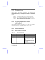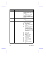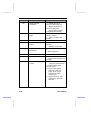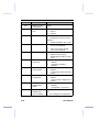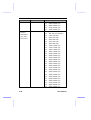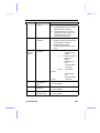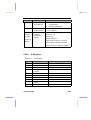
1
Premier Modem Series 56K External Modem Box User Manual P/N:P403-01 Copyright Copyright 2001 by this company. All rights reserved. No part of this publication may be reproduced, transmitted, transcribed, stored in a retrieval system, or translated into any language or computer language, in any form or by any means, electronic, mechanical, magnetic, optical, chemical, manual or otherwise, without the prior written permission of this company. Disclaimer This company makes no representations or warranties, either expressed or implied, with respect to the contents hereof and specifically disclaims any warranties, merchantability or fitness for any particular purpose. Any software described in this manual is sold or licensed "as is". Should the programs prove defective following their purchase, the buyer (and not this company, its distributor, or its dealer) assumes the entire cost of all necessary servicing, repair, and any incidental or consequential damages resulting from any defect in the software. Further, this company reserves the right to revise this publication and to make changes from time to time in the contents hereof without obligation to notify any person of such revision or changes. . All brand and product names mentioned in this manual are trademarks and/or registered trademarks of their respective holders. ii Regulatory Statements FCC Notice This equipment has been tested and found to comply with the limits for a Class B digital device, pursuant to Part 15 of FCC Rules. These limits are designed to provide reasonable protection against harmful interference in a residential installation. This equipment generates, uses, and can radiate radio frequency energy and, if not installed and used in accordance with the instructions, may cause harmful interference to radio communications. However, there is no guarantee that interference will not occur in a particular installation. If this equipment does cause harmful interference to radio or television reception, which can be determined by turning the equipment off and on, the user is encouraged to try to correct the interference by one or more of the following measures: 1. Reorient or relocate the receiving antenna. 2. Increase the separation between the equipment and receiver. 3. Connect the equipment into an outlet on a circuit different from that to which the receiver is connected. 4. Consult the dealer or an experienced radio/television technician for help. Notice 1: The changes or modifications not expressly approved by the party responsible for compliance could void the user's authority to operate the equipment. Notice 2: Shielded interface cables, if any, must be used in order to comply with the emission limits. iii FCC Requirement This equipment complies with Part 68 of the FCC rules. On the base unit of this equipment is a label that contains, among other information, the FCC Registration Number and Ringer Equivalence Number (REN) for this equipment. If requested, this information must be given to telephone company. The REN is useful in determining the quantity of devices you may connect to your telephone line and still have all of those devices ring when your telephone number is called. In most, but not all area, the sum of the REN of all devices connected to one line should not exceed five (5). To be certain of the number of devices you may connect to your line, as determined by the REN, you should contact your local telephone company to determine the maximum number of REN for your calling area. If your equipment causes harm to the telephone network, the telephone company may discontinue your service temporarily. If possible, they will notify you in advance. But if advance notice is not practical, you will be notified as soon as possible. You will be informed of your right to file a complain with the FCC. Your telephone company may make changes in its facilities, equipments, operations or procedures that could affect the proper functioning of your equipment. If they do, you will be notified in advance to give you an opportunity to maintain uninterrupted telephone service. The equipment may not be used on coin service by the telephone company. Connection to party lines is subject to state tariffs. IMPORTANT SAFETY INSTRUCTIONS 1. Read these instructions carefully. 2. Follow all warnings and instructions marked on the product. iv 3. Unplug this product from the wall outlet before cleaning. Do not use liquid cleaners or aerosol cleaners. Use a damp cloth for cleaning. 4. Do not use this product near water. 5. Do not place this product on an unstable cart, stand, or table. The product may fall, causing serious damage to the product. 6. The openings should never be blocked by placing the product on a bed, sofa, rug, or other similar surface. This product should never be placed near or over a radiator or heat register, or in a built-in installation unless proper ventilation provided. 7. This product should be operated from the type of power indicated on the marking label. If you are not sure of the type of power available, consult your dealer or local power company. 8. Do not allow anything to rest on the power cord. Do not locate this product where persons will walk on the cord. 9. If an extension cord is used with this product, make sure that the total ampere rating of the equipment plugged into the extension cord does not exceed the extension cord ampere rating. Also, make sure that the total rating of all products plugged into the wall outlet dose not exceed 15 amperes. 10. Do not attempt to service this product yourself, as opening or removing covers may expose you to dangerous voltage points or other risks. Refer all servicing to qualified service personnel. v About this Manual Purpose This user guide gives you all the information you need to install and operate the modem properly. Manual Structure This user guide consists of five chapters and one appendix: Chapter 1 Getting Started This chapter tells you what items are contained in the package and things that you need to check before you proceed with the installation of the modem. Chapter 2 Modem Overview This chapter gives you all the necessary information that you need to know about the modem, such as its features and layout. Chapter 3 Installing the Modem This chapter contains step-by-step procedure on how to install the modem and other necessary peripherals, configure the modem under Windows operating system, and verify the modem installation. Chapter 4 Communication Software This chapter gives tips on how to configure your modem Communication software. Chapter 5 AT Commands This chapter guides you on how to use the AT commands that will allow you to directly control fax/modem activities. vi Appendix A Troubleshooting This appendix gives tips on how to resolve the common problems that you might encounter when using the modem. Conventions The following conventions are used in this manual: Text entered by user , , , etc. Represents text input by the user. Represent the actual keys that you have to press on the keyboard. NOTE Gives bits and pieces of additional information related to the current topic. WARNING Alerts you to any damage that might result from doing or not doing specific actions. CAUTION Suggests precautionary measures to avoid potential hardware or software problems. IMPORTANT Reminds you to take specific action relevant to the accomplishment of the task at hand. TIP Tells how to accomplish a task with minimum steps through little shortcuts. vii Table of Contents Chapter 1 Getting Started 1.1 Package Contents ...................................................... 1-1 1.2 System Requirements ................................................ 1-2 Chapter 2 Modem Overview 2.1 Specifications................................................................... 2-1 2.2 Front Panel ...................................................................... 2-3 Chapter 3 Installing the Modem 3.1 ESD Precautions ........................................................ 3-1 3.2 Setting up the Modem ................................................ 3-1 3.3 Setting up your Modem for Windows 95……..………..3-3 3.4 Setting up your Modem for Windows 98………..…..…3-5 3.5 Setting up your Modem for Windows ME...……….……3-7 3.6 Setting up your Modem for Windows 2000….………..3-10 3.7 Setting up your Modem for Windows NT4.0..….……3-13 3.8 Testing Your Modem Installation.................…......….3.13 Chapter 4 Communication Software 4.1 Installing the Communication Software...................... 4-1 4.2 Tips on Configuring the Communication Software..... 4-1 Chapter 5 AT Commands viii 5.1 Entering a Command ................................................. 5-1 5.2 Repeating a Command (A/) ....................................... 5-2 5.3 Dialing (D) .................................................................. 5-2 5.4 Tone or Pulse Dialing (T or P) ................................... 5-3 5.5 Pause (,) .................................................................... 5-3 5.6 Wait for Second Dial Tone (W).................................. 5-4 5.7 Call Transfer or Other On Hook Feature (!)............... 5-4 5.8 Wait for Silence (@)................................................... 5-4 5.9 Storing Telephone Numbers (&Zn=t)......................... 5-5 5.10 Dialing Stored Numbers (S=n) ................................... 5-5 5.11 Answering a Call ........................................................ 5-5 5.11.1 Manual Answering (A)................................. 5-5 5.11.2 Auto-answering (S0=n) ............................... 5-6 5.12 Hanging Up or Going Off Hook (H)............................ 5-6 5.13 Selecting Response Message (Vn)............................ 5-7 5.14 Enabling/Disabling the Speaker (Mn) ........................ 5-7 5.15 Adjusting the Speaker Volume (Ln) ........................... 5-7 5.16 Reading an S-Register Value(Sn).............................. 5-8 5.17 Changing an S-Register Value (Sn=x)....................... 5-8 5.18 Sending Faxes ........................................................... 5-9 5.19 Checking Data or Fax Status (+FCLASS=?) ............. 5-9 5.20 Quick Reference ........................................................ 5-9 5.20.1 Data Modem Commands............................ 5-9 5.20.2 Fax Modem Commands ........................... 5-19 5.20.3 Voice Modem Commands ........................ 5-20 5.20.4 S-Registers…………………………………..5-23 Appendix A Troubleshooting ix List of Figures 3-2 Connecting Peripherals ............................................ 3-3 List of Tables x 2-1 LEDs........................................................................... 2-3 5-1 Basic AT Commands.................................................. 5-9 5-2 AT & Commands ..................................................... 5-12 5-3 AT % Commands ..................................................... 5-14 5-4 AT \ Commands ....................................................... 5-14 5-5 AT + Commands ...................................................... 5-15 5-6 AT Commands Results Codes ................................. 5-19 5-7 Fax Commands ....................................................... 5-20 5-8 Voice Commands ..................................................... 5-21 5-9 S-Registers............................................................... 5-24 Chapter 1 Getting Started Congratulations on your purchase of this Data/Fax/Voice modem . This modem features the latest innovation in high-speed modem design, making electronic communication faster and easier. It incorporates the full-duplex speakerphone technology that allows true simultaneous two-way conversation; thus, hand-free conversation and telephone conferences are made possible. This manual guides you on how to install and properly use the modem in order to take full advantage of its features. An appendix about troubleshooting is also included to help you fix minor problems that you might encounter while using the modem. 1.1 Package Contents Make sure that you have the following items: • • • • • • External Modem RJ11 telephone cable RS232 serial cable AC power adapter Quick Start Guide CD-Title with Application Software and manual If any of the items is damaged or missing, contact your dealer immediately. Getting Started 1-1 1.2 System Requirements Before you proceed, make sure that your system meets the following requirements: • • • 1-2 Penitum Based (above) IBM-compatible PC system with an empty PCI slot At least 16 MB memory Windows 9X/Windows ME/Windows NT 4.0/ Windows 2000 operation system User Manual Chapter 2 Modem Overview Before you proceed with the installation, it is necessary that you have enough information about the modem. This chapter tells you all you need to know about the modem. 2.1 Specifications Data Modem Operation • • • • • • Line Speed: 300 ~ 56000bps Standard Compatibility: V.90/K56Flex, ITU V.34, V.32,V.32bis, V.23, V.22bis, V.21, and Bell 103, 212A Error Correction: ITU-T V.42, MNP2-4 Data Compression: ITU-T V.42bis, MNP5 Flow Control: RTS/CTS, XON/XOFF Comment Set:: TIA/EIA 602 “AT” command set Fax Modem • • • Line Speed: 2400 ~ 14400bps Standard Compatibility: ITU-T V.17, V.27 ter,V.29 Command Set: EIA-578 Service Class 1 Voice Operation • Digital Telephone answering machine (TAM); Voice mail system Modem Overview 2-1 • • Voice Sampling Rate: 8-bit monophonic audio data encoding at 11.025KHz or 7200Hz FDSP: Full-duplex speakerphone with acoustic and line echo cancellation General Features • • • • • • Line Interface: 2xRJ-11 jacks for line and telephone DTE Interface: RS232C serial interface Voice Interface: 2x audio jack for microphone input and speaker output Ambient Temperature: • Operating: +10° ~ +50°C • Non-operating: -20° ~ +60°C Humidity: • Operating: 20% ~ 80% RH • Non-operating: 20% ~ 80% RH Dimensions: 135mm (L) x 95mm (W) x 25mm (H) 2.2 Front Panel The LED indicators located on the front panel report modem status and activity. The table below shows the function of each LED indicator: 2-2 User Manual Table 2-1 LEDs Label Name Description OH Off Hook CTS Clear to Send Lights when CTS signal is active RTS Ready to Send Lights when RTS signal is active RD Receive Data Flashes when modem is receiving data from a remote modem SD Send Data Flashes when modem is transmitting data to a remote modem CD Carrier Detect Lights when modem receives a valid data signal (carrier) from a remote modem TR Terminal Ready Lights when DTR signal is active MR Modem Ready Lights when power on Modem Overview Lights when modem is off hook 2-3 Chapter 3 Installing the Modem This chapter contains detailed instructions on how to install and configure the modem, as well as how to verify if your installation is correct. We recommend that you follow the steps accordingly to avoid future problems. 3.1 ESD Precautions Electrostatic discharge (ESD) can damage your processor, disk drives, expansion boards, and other system components. Always observe the following precautions before you install any system component. 1. Do not remove a component from its protective packaging until you are ready to install it. 2. Wear a wrist grounding strap and attach it to a metal part of the system unit before handling components. If a wrist strap is not available, maintain contact with the system unit throughout any procedure requiring ESD protection. 3.2 Setting up the Modem This external modem is easy to install. Just follow the instructions below. To install the modem: 1. Make sure that your system is turned off before you install the modem. Installing the Modem 3-1 2. Plug the male (9-pin) serial cable into the RS-232C connector at the back of the modem. See chapter 2 for the location of the connectors. 3. Plug the other end of the serial cable into your system’s serial port (COM1 or COM2 on your system). 4. Plug the telephone cable into the LINE jack located at the back of the modem. See chapter 2 for the location of the jack. 5. Plug the other end of the telephone cable into a telephone wall jack. 6. Plug the AC adapter power cord into the AC 9V connector located at the back of the modem. See chapter 2 for the location of the connector. 7. Plug the transformer end of the adapter into a standard AC wall outlet. 8. To connect a telephone to the modem: a. Plug the telephone to the modem PHONE jack. b. Lift the handset and listen for a dial tone to check for a working connection. 9. To connect a speaker and a mic to the modem: a. Plug the speaker in to the modem SPK connector. b. Plug the mic in to the modem MIC connector. 10. Turn your modem on. The modem should perform a self-test and then be ready for use. After every thing checks out, turn your computer on. NOTE: Make sure that your modem is turned off before you plug in the AC adapter. Also check the voltage range in your area before plugging your system into an outlet. 3-2 User Manual Fig 3-1 Connecting Peripherals 3.3 Setting Up your Modem for Windows 95 3.3.1 Installing Modem Drivers with Windows 95 Version 950 and 950a Windows 95 will automatically detect your new hardware when you first install it. To install the driver for your modem, follow the procedures as below: 1. Turn on your computer. As the Windows 95 operating system boots up, it displays a New Hardware Found dialog box on your screen for a few seconds with the identifier name (Premier V.90 56K xxxx series) of your modem. Installing the Modem 3-3 2. In the New Hardware Found dialog box, you have three choices to install a driver. The default choice is for the driver to be installed from a disk provided by the hardware manufacturer. Highlight this selection if it is not already highlighted and click OK. 3. Make D:\ the default drive for the source location. 4. Insert the drive CD into to the CD-ROM and click OK. 5. Windows 95 will auto-detect the correct files and copy them onto your hard disk. 3.3.2 Installing Modem Drivers with Windows 95 Version 950b 1. Turn on your computer. As the Windows 95 operating system boots up, it displays a Updated Device Driver Wizard dialog box shown on your screen. 2. Insert the driver CD into the CD-ROM drive and click NEXT. 3. After Windows 95 finishes searching for updated drivers, click Finish. 3-4 User Manual 4. Windows 95 will copy the files onto your hard disk. 5. After Windows 95 finishes copying files, it will detect another device call Voice Modem Serial Wave Device. Simply follow the same instructions as above for the Wave Device installation. 3.4 1. Setting Up Your Modem for Windows 98 Turn on your computer. As the Windows 98 operating system boots up, it displays a Add New Hardware Wizard dialog box shown on your screen for a few seconds with the identifier name (Conexant SmartSCM External PnP Modem) of your modem. Installing the Modem 3-5 2. Click NEXT, then a new dialog box will show on the screen. 3. In the new dialog box, you have two choices to install a driver. The default choice is search for the best driver for your device. Highlight this selection if it is not already highlighted and click NEXT. 4. A new Add New Hardware Wizard dialog box will display on the screen. 3-6 User Manual 5. Insert the driver CD into the CD-ROM drive and highlight the Specify a location selection and click browse button to find out the “D:\driver\Win9x “ .Then click NEXT. 6. Windows 98 will copy the files onto your hard disk. 7. After Windows 98 finishes copying files, it will detect another device call Wave Device for Voice Modem. Simply follow the same instructions as above for Wave Device installation. 3.5 Setting Up Your Modem for Windows ME Installing the Modem 3-7 Turn on your computer. As the Windows ME operating system boots up, it displays a Add New Hardware Wizard dialog box shown on your screen for a few seconds with the identifier name (Conexant SmartSCM External PnP Modem) of your modem. 1. Click NEXT, then a new dialog box will show on the screen 3-8 User Manual 2. Insert the driver CD into the CD-ROM drive and click browse button to find out the “D:\driver\WinME “ .Then click NEXT. 3. Windows ME will copy the files onto your hard disk. 4. After Windows ME finishes copying files, it will detect another device call Wave Device for Voice Modem. Simply follow the same instructions as above for Wave Device installation. Installing the Modem 3-9 3.6 Setting Up Your Modem for Windows 2000 1. Turn on your computer. As the Windows 2000 operating system boots up, it displays a Found New Hardware Wizard dialog box shown on your screen. 2. Click NEXT, then a new dialog box will show on the screen. 3-10 User Manual 3. In the new dialog box, you have two choices to install a driver. The default choice is search for the best driver for your device. Highlight this selection if it is not already highlighted and click NEXT. Installing the Modem 3-11 4. A new Found New Hardware Wizard dialog box will display on the screen. 5. Insert the driver CD into the CD-ROM drives and highlight the “specify a location” and click NEXT . 6. Windows 2000 will copy the files onto your hard disk. 5. After Windows 2000 finishes copying files, it will show " Windows has finished installing the software for this device". Then click FINISH. 3-12 User Manual 3.7 Setting Up Your Modem for Windows NT4.0 1. After Windows NT boot, double click on the Modems icon. 2. At the Install New Modem screen, check the box in front of “Don’t Detect my Modem, I will select it from a List”. 3. Select Next, then Have Disk. Insert the driver CD into the CD-ROM drive. 4. Type D:\driver\WinNT4.0, then click OK.. 5. Highlight and select the modem which corresponds to the one you purchased, then click NEXT. 6. Select the COM port to which the modem was attached. Then select NEXT, then Finish. 7. Windows NT will copy the files onto the hard disk. 3.8 Testing Your Modem Installation To test if you have installed the modem properly: 1. Perform the software function that puts your system in Terminal mode. For Windows 95/98/2000: Use the Hyper Terminal program. In Terminal mode, a cursor appears on the screen, allowing you to send commands directly to the modem. 2. To check if your system and modem are functioning properly, type: AT&F<Enter> Installing the Modem 3-13 The modem should respond OK, if any of the following screen problems occur, refer to Appendix A for troubleshooting tips. • The characters you type do not appear • No OK message appear • Double characters appear After you have successfully installed the modem, your next step is to configure the Communication software. For details, see Chapter 4. 3-14 User Manual Chapter 4 Communication Software This chapter gives you tips on how to configure your communication software. 4.1 Installing the Communication Software The Modem package comes with a Communication software disk and manual. To install the Communication software,simply insert the communications software CD into the CD-ROM drive,under Win9X/ME/NT/2000, the auto-run function will start the shell program, just follow the instruction on the screen for software installation. If you want to use other communication program, please refer to section 4.2. 4.2 Tips on Configuring the Communication Software This modem uses the most up-to-date industry and commercially popular standards to ensure functional compatibility with most communication software. During initial setup of the communication software, it will normally prompt you to define the type of fax/modem that you are currently using. The following list guides you on how to select the proper device type. The device type only defines the protocol by which your software will communicate with your fax/modem and does not set nor limit the speed. Communication Software 4-1 1. For the Baud rate, choose any speed between 38,400 to 115,200. Your fax/modem will automatically adjust to the optimum transmission speed after successfully connecting with a remote fax/modem. 2. Many communication software use the modem response to control program flow. Make sure that the software is set to recognize a CONNECT 28800 response. If this does not work, set the program to simply recognize just the CONNECT response without any baud rate information. 3. There are three flow controls: none, hardware (CTS/RTS), and software (XON/XOFF). Set your software to use either hardware or software flow control. If set to none, the communication software will not be able to detect a buffer overflow and result in transmission errors. 4. For fax device type, choose TR29 Class 1. 5. For fax speed, choose automatic or fastest speed. Your fax/modem will automatically adjust to the optimum transmission speed after successfully connecting with a remote fax machine or another fax./modem. 6. Make sure that you have correctly set all the other parameters required by the software to operate successfully. 7. Refer to your Communication software manual for details. You are now ready to do fax/modem communication. See Chapter 5 for details. 4-2 User Manual Chapter 5 AT Commands The AT commands are used to directly handle fax/modem data activities, such as dialing or answering a data call or sending a fax. To send commands to your modem, you must access the modem in a terminal mode which is provided by most communication software. Also, you need to know the format for typing the fax/modem commands and responses. This chapter tells you how to properly use the AT commands. If you will be using a communication software program to do fax/modem communication, you will probably not need to type the commands because the software program will handle these tasks for you. Similarly, you will not see the response because your software program may intercept them. 5.1 Entering a Command To enter a command: 1. Type AT. This is the Attention Code informing the modem that a command follows. The Attention Code may be in upper or lower case. 2. Type the command. Refer to the succeeding sections. 3. Press to send the command to the modem (except for A/ and +++ commands). AT Commands 5-1 For example: ATccpp where: AT: Attention Code cc: any command pp: any parameter that is required by the command The following sections tell how to enter basic commands. The other commands are described in the AT_CMD.TXT file contained in the fax/modem driver diskette. You may use DOS EDIT or any suitable editor to view this file. 5.2 Repeating a Command (A/) The A/ command tells the modem to repeat the last command you entered. When entering this command, DO NOT type the AT after before this command and DO NOT press entering the command. 5.3 Dialing (D) The D command dials the phone number. For example, to dial the number 02-1234-5678, type: ATD12345678 Then press 5-2 . All three entries are treated the same. User Manual You may use numbers 0~9 in all dial strings. You may also use spaces, hyphens, parentheses, or any other punctuation except the dial modifiers to make the command line easier to read. 5.4 Tone or Pulse Dialing (T or P) To tone or pulse dial a number sequence, insert a T or P between the dial command (D) and the phone number. The modem prepares for tone dialing. If you have used P in the last dial string, you only need to enter a T in the dial string. For example: ATDT(or P)12345678 5.5 Pause (,) Inserting a Pause command in the dial string inserts either a 2-second pause or the value in status register S8 in the dialing sequence. For example: ATDP,12345678 AT Commands 5-3 5.6 Wait for Second Dial Tone (W) The W command makes the modem pause and listen for a second dial tone before continuing the dial command. For example: ATDW0212345678 You can use the pause and wait for second dial tone commands when using long distance services. 5.7 Call Transfer or Other On Hook Feature (!) Enter an exclamation mark (!) to transfer a call or do something similar that requires on-hook or ″flash-hook”. For example: ATDT9,323-8000!,#7377 5.8 Wait for Silence (@) The Wait for Silence command is used for special service like automatic paging. The @ modifier tells the modem to wait for one or more rings then listen for 5 seconds for continuous silence before dialing. If 5 seconds of silence is not detected within the time set in register S7, the modem hangs up. 5-4 User Manual 5.9 Storing Telephone Numbers (&Zn=t) The modem can store up to four sets of telephone numbers; each set dial string can contain up to 34 digits. To store telephone numbers including all the dial modifiers that you may need, enter: AT&Zn=t where: n = locations 0~3 t = 0~9, *, # and any of the dial modifiers T, P, W, @, ;, !. For example, to store the dial sequence T9,1551212 at location 2, type: AT&Z2=T9,1551212 5.10 Dialing Stored Numbers (S=n) Enter ATDS=n to dial the phone number stored at location n (where n=0~3). 5.11 Answering a Call 5.11.1 Manual Answering (A) The factory presets the modem to answer a call only when you enter ATA. This is useful especially if you are using only one telephone line for your modem and telephone. AT Commands 5-5 5.11.2 Auto-answering (S0=n) The modem default setting is not to answer a call unless you manually enter the ATA command. However, if you have a separate telephone line for the modem and your telephone, you can set the modem to automatically enter incoming calls. You can specify the number of rings before the modem answers the call. To specify, type: ATS0=n where: n: is the number of rings after which, the modem answers the call. The settings are from 1~255. Set S0=0 to disable auto-answer (default setting). 5.12 Hanging Up or Going Off Hook (H) Enter: 5-6 ATH to let the modem hang up. ATH1 to let the modem go off-hook User Manual 5.13 Selecting Response Message (Vn) The V commands tell the modem to show response messages as words or numbers. See Table 5-7 for the list of response messages in both numbers and words. Enter: V0 Enables number response message. V1 Enables word response message. 5.14 Enabling/Disabling the Speaker (Mn) This command lets you enable or disable the speaker. Enter: Speaker always off Speaker on until carrier present ( default ) Speaker always on Speaker off during dialing ; speaker on until carrier Present M0 M1 M2 M3 5.15 Adjusting the Speaker Volume (Ln) This command sets the audio output of the speaker. Enter: AT Commands 5-7 Low speaker volume Low speaker volume ( default ) Media speaker volume High speaker volume L0 L1 L2 L3 5.16 Reading an S-Register Value(Sn) To read the current value of an S-Register, type: ATSn? where n is an S-Register number. The modem responds with decimal value of the S-Register, in three-digit format followed by OK. To read values from more than one S-Register, type: ATSn?Sn? where n specify the different S-Register numbers. 5.17 Changing an S-Register Value (Sn=x) To change an S-Register value, type: ATSn=x where: n: S-Register number x: value you want to assign to the specified S-Register 5-8 User Manual 5.18 Sending Faxes You can send a fax using the fax software. The commands are automatically issued by the fax software. In case you encounter some problems while sending or receiving a fax, refer to your fax software manual. Some fax packages require software flow control. The modem uses the hardware flow control as the factory default. You may need to enable the software flow control to send and receive faxes. 5.19 Checking Data or Fax Status (+FCLASS=?) This command identifies if the modem is set for data or fax operation. The possible values are 0 for data mode and 1 for fax class 1. 5.20 Quick Reference 5.20.1 Data Modem Commands Table 5-1 Basic AT Commands Command Description Function A/ Re-execute Command None A Answer None Bn ITU-T or Bell 0 = Selects ITU-T V.22 at 1200 bps and ITU-T, V.21 at 300 bps 1 = Selects Bell 212A at 1200 bps and Bell 103J, at 300 bps ( default ) 2 = Selects ITU-T V.23 only. AT Commands 5-9 Command Description Function The originating modem , transmits at 75 bps ; the answering mode, transmits at 1200 bps. 3 = Selects ITU-T V.23 only. The originating modem, transmits at 1200 bps ; the answering modem transmits at 75 bps. Cn Carrier Control 0 = Transmit carrier always off ( default ) Dn Dial N can equal a character string using any of the following: 1 = Normal transmit carrier z 0,1,2,3,4,5,6,7,8,9 ( Dialing Digit ) z *,#,A,B,C or D (Tone Dial Characters) z L Redial last number: the modem responds with Error if ATDL is issued. If L is embedded in the dial string, it is considered as a presentation character and hence ignored. z P (Pulse Dial) z T (Tone Dial) z R (Reverse originate mode) z S=n(Dial NVRAM telephone number) z ! (Flash Hook) z W (Wait for dial tone) z @ (Wait for silence) z , (Pause) z ; (Return to command state) 5-10 User Manual Command Description Function z -() (Ignored by modem) En Command echo 0 = Disable echo 1 = Enable echo ( default ) Fn Online echo 0 = Enable online echo 1 = Disable online echo ( default ) Hn Switch hook control 0 = Hangs up the telephone line ( default ) 1 = Picks up the telephone line In Identification 0 = Reports product code 1 = Least significant byte 2 = Reports "OK". 3 = Identification codes 4 = Reports OEM defined identifier string 5 = Country code 6 = Data pump model Ln Speaker Volume 0 = Low speaker volume 1 = Low speaker volume ( default ) 2 = Medium speaker volume 3 = High speaker volume Mn Speaker Control 0 = Speaker always off 1 = Speaker on until carrier present ( default ) 2 = Speaker always on 3 = Speaker off during dialing; speaker on until carrier present AT Commands 5-11 Command Nn Description Select data rate handshake Function 0 = Handshake only at DTE-to-modem data rate 1 = Begins handshake at DTE-to-modem data rate and falls to highest compatible rate (default) On Return to online Data Mode 0 = Returns to online without retrain ( default ) 1 = Returns to online with retrain Set Pulse Dial None Qn P Result code display control 0 = Enables result codes (default) Sn Read/write 1 = Disables result codes S-Register n =x Write value x to S –register n ? Read S-register n T Vn Set Tone Dial Default tone dial Result Code Form 0 = Choose numeric form 1 = Choose verbose (text) form (default) Wn Connect Message Control 0 = Reports DTE speed response codes (default). 2 = Reports DCE speed response codes 3 = Reports DTE speed response codes and inform- ation on error correction and data compression 4 = Reports protocol, data compression, and DTE data rate 5-12 User Manual Command Description Xn Result Codes type Function 0 = Blind dial, no busy detect, CONNECT 1 = Blind dial, no busy detect, CONNECT XXXX 2 = Dial tone detect, no busy detect, CONNECT XXXX 3 = Blind dial, busy detect, CONNECT XXXX 4 = Full monitor, all messages, CONNECT XXXX(default) Zn Soft Reset and Restore Profile 0 = Soft reset and restore profile0 ( default ) 1 = Soft reset and restore profile1 Table 5-2. AT & Commands Command &Cn Description DCD option Function 0 = DCD always on 1 = DCD normal (default) &Dn DTR option 0 = In Async mode, modem ignores DTR 1 = Modem switches from data mode to command mode when an on-to-off transition of DTR occurs 2 = When DTR switches off, the modem goes onhook and disables Auto-answer mode; when DTR switches on, auto-answer is enabled ( Default ) 3 = Turning off DTR re-initializes the modem and resets values except UART registers AT Commands 5-13 Command Description Function &Fn Restore Factory Configuration None &Gn Select Guard Tone 0 = Disable ( default ) 1 = 550 Hz 2 = 1800 Hz &Kn Flow Control 0 = Disable 3 = Enable RTS/CTS flow control ( default ) 4 = Enable XON/XOFF flow control &Pn Dial pulse ratio 0 = Sets 10-pps pulse dial with 39%/61% make/break 1 = Sets 10-pps pulse dial with 33%/67% make/break &Sn DSR Override 0 = DSR always on ( default ) 1 = DSR active only during handshaking and when carrier is lost &Tn &Vn &Wn Self Test commands 0 = Terminates test in progress ( default ) 1 = Initiates local analog loopback 0 = View active profile and stored profile 0 1 = View active profile and stored profile 1 0 = Store current configuration as profile 0 1 = Store current configuration as profile 1 Designate a Default Reset Profile 0 = Use profile 0 on power up ( default ) 1 = Use profile 1 on power up Store Telephone Number (0-3) 0 to 3 Specified telephone number ID (up to 30 digits) x up to 30 digits for the telephone View active and stored profiles Store Current Configuration &Yn &Zn=X 5-14 User Manual Command Description Function number to be saved Table 5-3. AT % Commands Command Description %Cn MNP 5 data compression control %En Auto-retrain control Function 0 = No compression 1 = Enables MNP5 data compression ( default ) 2 = Disables auto-retrain 3 = Enables auto-retrain ( default ) Table 5-4. AT \ Commands Command \Nn Description Operating Mode AT Commands Function 0 = Selects Buffer (Normal) mode with speed buffering 1 = Selects Buffer (Normal) mode with speed buffering 2 = Selects MNP Reliable mode 3 = Selects V.42 Auto-reliable mode ( default ) 4 = Selects V.42 Reliable mode 5-15 Table 5-5. AT + Commands Command +MS <carrier>, Description Select Modulation Function <carrier> Description V21 V.21 300 bps <automode>, V22 V.22 1200 bps <min_rate>, V22B V.22 bis 1200 and 2400 bps <max_rate> V23C V.23, with constant carrier; 1200bps forward and 75bps reverse V32 V.32 4800 and 9600 bps V32B V.32 bis 7200, 9600, 12,000, and 14,400 bps V34 V.34 asymmetrical connections: 2400, 4800, 7200, 9600, 12,000, 14,400, 16,800, 19,200, 21,600, 24,000, 26,400, and 28,800 bps V.90 56-kbps V.90 asymmetrical Connections (transmit): 4800, 7200, 9600, 12,000, 14,400, 16,800, 19,200, 21 600 24 000 5-16 User Manual Command Description Function 26,400, 28,800, 31,200, 33,600bps (receive): 28,000, 29,333, 30,667, 32,000, 33,333, 34,667, 36,000, 37,333, 38,667, 40,000, 41,333, 42,667, 44,000, 45,333, 46,667, 48,000, 49,333, 50,667, 52,000, 53,333, 54,667, and 56,000bps <automode> 0 = disabled 1 = enabled ( default ) +MS <carrier>, Select Modulation <min_rate> z 300 300 bps ( default ) <automode>, z 1200 1200 bps <min_rate>, z 2400 2400 bps <max_rate> z 4800 4800 bps z 7200 7200 bps z 9600 9600 bps z 12000 12000 bps z 14400 14400 bps z 16800 16800 bps z 19200 19200 bps z 21600 21600 bps z 24000 24000 bps z 26400 26400 bps AT Commands 5-17 Command Description Function z 28000 28000 bps z 28800 28800 bps z 31200 31200 bps z 33600 33600 bps +MS <carrier>, Select Modulation <max_rate> z 300 300 bps ( default ) <automode>, z 1200 1200 bps <min_rate>, z 2400 2400 bps <max_rate> z 4800 4800 bps z 7200 7200 bps z 9600 9600 bps z 12000 12000 bps z 14400 14400 bps z 16800 16800 bps z 19200 19200 bps z 21600 21600 bps z 24000 24000 bps z 26400 26400 bps z 28000 28000 bps z 28800 28800 bps z 29333 29333 bps z 30666 30666 bps z 31200 31200 bps z 32000 32000 bps z 33333 33333 bps z 33600 33600 bps z 34000 34000 bps z 34666 34666 bps z 36000 36000 bps z 37333 37333 bps z 38000 38000 bps z 38666 38666 bps 5-18 User Manual Command Description Function z 40000 40000 bps z 41333 41333 bps z 42000 42000 bps z 42666 42666 bps z 44000 44000 bps z 45333 45333 bps z 46000 46000 bps z 48000 48000 bps z 49333 49333 bps z 50000 50000 bps z 50666 50666 bps z 52000 52000 bps z 53333 53333 bps z 54000 54000 bps z 54666 54666 bps z 56000 56000 bps (default) z 58000 58000 bps z 60000 60000 bps +MS? Responds with + MS setting (e.g.,+ MS:56,1,300,600 00, 60000,0,0) AT Commands 5-19 Table 5-6. AT Command Result Codes Numeric OK 0 CONNECT 37333 34 CONNECT 1 CONNECT 41333 35 RING 2 CONNECT 42667 36 NO CARRIER 3 CONNECT 44000 37 ERROR 4 CONNECT 45333 38 CONNECT 1200 5 CONNECT 46667 39 NO DIALTONE 6 CONNECT 48000 42 BUSY 7 CONNECT 49333 43 NO ANSWER 8 CONNECT 49333 43 CONNECT 2400 10 CONNECT 50667 53 CONNECT 4800 11 CONNECT 52000 54 CONNECT 9600 12 CONNECT 53333 55 CONNECT 14400 13 CONNECT 54666 56 CONNECT 7200 13 CONNECT 56000 57 CONNECT 19200 14 CONNECT 57333 58 CONNECT 57600 18 CONNECT 21600 61 CONNECT 7200 24 CONNECT 24000 62 CONNECT 12000 25 CONNECT 26400 63 5-20 Text Message Numeric Text Message Value Value User Manual Numeric CONNECT 38400 28 CONNECT 28800 64 CONNECT1 15200 31 CONNECT 31200 65 CONNECT 33333 33 CONNECT 33600 66 5.20.2 Text Message Numeric Text Message Value Value Fax Modem Commands Table 5-7. Fax Commands Command Description +FCLASS=n Mode selection Function 0 = Data mode (default) 1 = Class 1 fax mode 8 = Voice mode enabled +FRH=n Receive HDLC data 3 +FRS=n Wait for silence 1-255 (x10ms) +FTM=n Transmit Data 24 =V.27ter 2400 bps 48 =V.27ter 4800 bps 72 =V.29 7200 bps 73 =V.17 7200 bps long 74 =V.17 7200 bps short 96 =V.29 9600 bps 97 =V.17 9600 bps long 98 =V.17 9600 bps short 121 =V.17 12000 bps long 122 =V.17 12000 bps short AT Commands 5-21 Command Description Function 145 =V.17 14400 bps long 146 =V.17 14400 bps short +FRM=n Receive Data 24 =V.27ter 2400 bps 48 =V.27ter 4800 bps 72 =V.29 7200 bps 73 =V.17 7200 bps long 74 =V.17 7200 bps short 96 =V.29 9600 bps 97 =V.17 9600 bps long 98 =V.17 9600 bps short 121 =V.17 12000 bps long 122 =V.17 12000 bps short 145 =V.17 14400 bps long 146 =V.17 14400 bps short +FTH=n Transmit Data with 3 =V.21 300 bps +FRH=n Receive Data with HDLC Framing 3 =V.21 300 bps HDLC Framing 5.20.3 Voice Modem Commands Table 5-8. Voice Commands Command Description +FCLASS =n Mode selection Function 0 = Data mode (default) 1 = Class 1 fax mode 8 = Voice mode enabled +FLO=n 5-22 Flow Control 0 = Disable XON/XOFF and User Manual Command Description Select Function CTS/RTS flow control 1 = Enable XON/XOFF flow control in either direction ( default ) 2 = The DTE uses ITU-T's RTS to control flow to the modem ; the modem uses ITU-T CTS to control flow to the DTE +VCID=n Caller ID Selection 0 = Disables Caller ID ( default ) 1 = Enables Caller ID with formatted presentation to the DTE. 2 = Enables Caller ID with unformatted presentation to the DTE. +VDR= <enable>, <report> Distinctive Ring Selection <enable> <report> Function 0 --- Distinctive ring disable 1 0 The modem reports DROF and DRON Messages but does not report RING messages 1 reports none,0 The modem DROF,DRON and RING messages 2-255 +VGM=n +VGR=n +VGS=n Speakerphone Microphone Gain n=121-131 Receive Gain Selection n=121-131 Speakerphone Speaker Gain n=121-131 AT Commands --- Reserved n=128 ( default ) n=128 ( default ) n=128 ( default ) 5-23 Command +VGT=n +VIT=n Description Function Volume Selection n=121-131 DTE/DCE Inactivity Timer n=0-255 ( units of 1.0 second ) n=128 ( default ) n=0 Disables inactivity timer ( default ) n≠0 Inactivity timer active +VNH=n Automatic Hang-UP Control 0 = The modem retains automatic hang-up as normal in data and fax modes ( default ) 1 = The modem disable automatic hang-up usually found in non-voice modes 2 = The modem disable all automatic hang-up usually found in non-voice modes except a 'logical' hang-up +VRA=n Ringback-GoesAway Timer n=0-50 ( in 100ms increments ) n=0 The DCE returns the 'OK' code immediately after ringback n=50 ( default ) +VRN=n Ringback-Never -Appeared Timer n=0-255 ( in 1-second increments ) n=0 The DCE returns the 'OK' code immediately after dialing n=10 ( default ) +VRX Record Mode This command causes the modem to enter record mode to record voice messages +VTX Play Mode This command causes the modem to start voice transmission ( playback mode ) and play back a previously recorded voice messages +VSP=n Speakerphone On/Off Control 0 = Speakerphone mode disabled (default ) 1 = Speakerphone mode enabled 5-24 User Manual Command Description #VSPS=n Speakerphone Type Selection +VTD=n Beep Tone Duration Timer Function 0 = Telephone Emulation Mode speakerphone 1 = Digital Speakerphone +VSD= Silence Detection ( Quiet and Silence ) <silence sensitivity > n=5-255 ( units of 10ms ) n=100 ( default ) <silence sensitivity> range=121-131 default=128 <length of silence > ,<length of silence> range=0-255 ( units of 0.1 second) value=0 Silence detection disabled default=50 Silence detection enabled 5.20.4 S-Registers Table 5-9. S-Registers Register Function Range S0 Rings to Auto-Answer 0-255 ( default = 0 ) S1 Ring Counter 0-255 ( default = 0 ) S2 Escape Character 0-127 ( default = 43 ) S3 Carriage Return Character 0-127 ( default = 13 ) S4 Line Feed Character 0-127 ( default = 10 ) S5 Backspace Character 0-32,127 ( default = 8 ) S6 Wait before Dialing 2-255 ( default = 2 ) Units: 1second S7 Wait Time for Carrier 1-255 ( default = 60 ) Units: 1second S8 Pause time for dial modifier 0-255 ( default = 2 ) Units: 1second S9 Carrier recovery time 1-255 ( default= 6 ) Units: 0.1second AT Commands 5-25 S10 Carrier Loss Disconnect Time 1-255 (default = 14 ) Units: 0.1second S11 DTMF Tone Duration 50-255 ( default = 70 ) Units: 1ms S12 Guard Time 0-255 ( default = 50 ) Units: 20ms S14 Bit-mapped Options Default = 138 S16 Modem Test Options Default = 0 S18 Modem Test Timer 0-255 ( default = 0 ) Units: 1second S21 Bit-mapped Options Default = 48 S22 Bit-mapped Options Default = 118 S23 Bit-mapped Options Default = none S25 Detect DTR Change 0-255 ( default = 5 ) Units: 10ms S27 Bit-mapped Options Default = 64 S30 Disconnect Inactivity Timer 0-255 ( default = 0 ) Units: 1minute S31 Bit-mapped Options Default = 49 S33 Sleep Mode Timer 0-90 ( default = 10 ) Units: 1second S37 Maximum Line Speed Attempted 0-35 ( default = 0 ) S91 Select transmit level 0-15 ( default = 10 ) Units: -dBm S92 DTMF transmit level 0-15 ( default = 10 ) Units: -dBm 5-26 User Manual Appendix A Troubleshooting This appendix contains information that will help you solve some of the common problems you might encounter while using the modem card. For further assistance, contact your dealer. Modem does not respond to AT commands • • • • There may be a COM port/IRQ conflict. Reconfigure the modem COM port address and IRQ line. Make sure that you have set the correct COM port and IRQ in the communications software. Make sure the system communications software. is in Terminal mode of your Reset the modem to its factory defaults by typing AT&F. Double characters display on your monitor • Both your modem and software local echoes are on. Turn off your modem local echo by typing the ATE0 command. Modem cannot dial and ″NO DIALTONE” message appears on the monitor • • Check the phone cord connection. Make sure that the jack on the modem labeled Line is connected to an analog phone wall jack. The modem cannot recognize the dial tone. This is typical in some corporate PBXs. Use the ATX1 command in your setup string to enable Blind Dial. Troubleshooting A-1 Both modems exchange carrier signals but fail to establish a connection • • Place the call again. The telephone company routes every call differently each time you call. Try calling a different modem to check if your modem is working. The modem does not answer an incoming call • Auto-answer function is disabled. Enable the function through software program or by sending the ATS0=1 command to your modem in terminal mode. The modem disconnects while online • • This may be caused by line interference. Retry the connection by dialing the numbers several times. An incoming call may have broken the connection if the Callwaiting feature is enabled. Disable Call-waiting and try again. Garbage characters display on the monitor • • • • A-2 Set your modem to the same word length, parity, and stop bits as the remote modem. Make sure that your software and modem are set to the same flow control setting. The software may not be set for correct terminal emulation. Configure the software to correct type. ANSI terminal emulation is the most commonly used. Type the AT&F1 command to load the template that enables hardware flow control as other optimal settings. User Manual Your communication software is reporting many cyclic redundancy check (CRC) errors and low characters per second (CPS) • • • • You might have experienced noise on the phone line. Place the call again. The phone company routes call differently each time you call. Type the AT&F1 command to load the template that enables the hardware flow control as other optimal settings. Lower the serial port rate in your communication software to 38,400 bps or 19,200 bps. Try a different file transfer protocol (do not use the XMODEM if other protocols are available). You cannot run the fax and communications software at the same time • • Communication devices can be accessed by only one application at a time. In Windows 9X/ME/NT/2000, you can open data and fax communications at the same time, but they cannot use the same modem at the same time. Troubleshooting A-3