1
Service/Technical
Manual
Diagraph PA/4000
Label Printer/Applicator
5802-929
Revision A
TM
B Y
A L L E N
-
B R A D L E Y
T E C H N O L O G Y
3401 Rider Trail South • St. Louis/Earth City, MO. • 1-800-521-3047, ServiceLine 1-800-526-2531
Diagraph Corporation ©2000
Diagraph PA/4000
OPERATIONS MANUAL
5802-928
Revision F
Information contained in this manual is commercially confidential and may not be reproduced or
disclosed without the written permission of Diagraph, Inc. The supply of this manual or the equipment
to which it applies does not constitute or imply the transfer of any rights to any party.
The information contained in this manual is correct and accurate at the time of its publication.
Diagraph reserves the right to change or alter any information or technical specifications at
any time and without notice.
©2000 Diagraph, Inc. All rights reserved.
Printed in the United States of America
400.U0F46.D1
PA/4000 Operations Manual
Table of Contents
Page 1
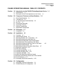
PA/4000 OPERATIONS MANUAL TABLE OF CONTENTS
Section 1.0 Introduction to the PA/4000 Printer/Applicator Series 1-1
1.1
1.2
Specifications 1-1
Description of the Printer/Applicators in the Series
Section 2.0 Component Features and Specifications
2.1
2.2
2.3
2.4
2.5
2.6
2.7
2.8
Containers
Section 4.0 Installation
4.1
4.2
4.3
4.4
4.5
4.6
4.8
4.9
4.10
4.11
4.12
4.15
4.16
4.17
4.18
4.19
4.20
4.21
3-1
3-1
4-1
Overview 4-1
Assembling the Stand 4-1
Mounting the Main Unit to the Stand 4-4
Mounting Attachments to the Main Unit
Mounting the Hand-Held Terminal and Holster
Mounting the Air Filter Assembly to the Stand
Mounting the Optional Warning Tower to the Stand
Mounting the Photosensor 4-6
Mounting the Optional Secondary Wipe-Down 4-7
Electrical Connections 4.8
DIP Switch Settings
Loading the Label Roll 4-14
Loading the Ribbon Roll 4-15
Testing the PA/4000 4-14
Setting the Baud Rate and Word Length
Minimum and Maximum Distances for the PA/4000
Final Positioning 4-17
Secondary Wipe-Down Assembly 4-20
Section 5.0 Configuration
5.1
5.2
2-1
Floor Stand Assembly 2-1
The Main Unit 2-5
Air Cylinder/Tamp Head Assembly 2-6
Air Filter 2-7
Photosensor Assembly
Hand-Held Terminal
Optional Components
Replaceable Components
Section 3.0 Packaging
3.1
1-1
Hand-Held Terminal Configuration
PA/4000 Remote IO Configuration
5-1
5-2
4-6
PA/5000 Operations Manual
Table of Contents
Page 2
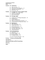
Section 6.0 Operations
6.1
6.2
6.3
6.4
Start of the Day 6-1
Adjustments during Operation 6-1
Stopping Label Application 6-1
End of Day 6-2
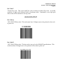
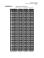
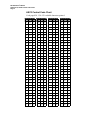
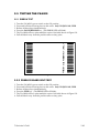
Section 7.0 Prodigy PlusTM Fonts and Bar Codes
7.1
7.2
7.3
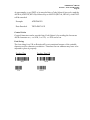
Available Fonts and Bar Codes
Internal Font Examples
Bar Code Examples
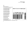
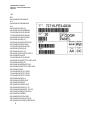
Section 8.0 Printing Labels
8.1
8.2
8.3
8.4
8.5
Prodigy PlusTM Print Engine Description 8-1
Media Supplies
Sample Label Printout
Start-up and Shut down Procedures 8-1
Printing Labels with Performance Series 8-1
Section 9.0 Maintenance
9.1
9.2
9.3
9.4
9.5
9.6
Daily Maintenance 8-1
Weekly Maintenance 8-1
Monthly Maintenance 8-1
Six Month Maintenance 8-2
Intermittent Maintenance 8-2
Yearly Maintenance
Section 10.0 Troubleshooting
10.1
10.2
10.3
10.4
10.5
Diagnostics 9-1
Power Problems 9-2
Printing Problems 9-3
Tamping Problems 9-6
Error & Warning Messages
9-16
Section 11.0 Service Parts and Kits
Appendex A
Appendex B Cable and Pin Connections
Glossary
Index
PA/4000 User’s Manual
Section 1, Product Features
Page 1
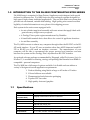
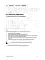
1.0 INTRODUCTION TO THE PA/4000 PRINTER/APPLICATOR SERIES
PA/4000 Series is comprised of three Printer/Applicators each designed with special
features for different uses. PA/4000 Series are print and apply systems designed for
high-speed, high-volume industrial applications. They are next-label-out systems that
provide true on-demand, variable data labeling. High quality print ensures excellent
legibility of critical information at every phase of the shipping process.
Each system in the series comes equipped with:
• An air cylinder tamp head assembly with auto-retract that apply labels with
great accuracy at high conveyor speeds
• A Prodigy PlusTM print engine manufactured by DataMax
• A hand-held terminal device that allows for control of applicator functions
• An air filter assembly
The PA/4000 connects to almost any computer through either the RS-232C or the RS422 serial interface. If your PC uses an interface other than ASCII character based RS232 or RS-422 you will need an interface converter. The manufacturer of your
computer will be able to recommend the proper protocol and interface converter
between the system and the Prodigy Plus’s asynchronous RS-232C interface.
An optional software package recommended by Diagraph, called Performance Series for
Windows™, is available for creating, storing, and printing label formats from IBM® or
compatible - personal computers.
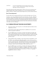
The PA/4000 has a full-range of options available. It is flexible and can address a
variety of design and custom application requirements:
1.
2.
3.
4.
5.
1.1
Product labeling using labels as large as 4.5 inches x 13 inches
Colored ribbons are available
Pharmaceutical and electronics packaging
Popular UPC bar codes
High-quality fonts and graphics
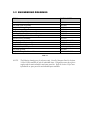
Specifications
Input Devices
Communications
Software
(recommended)
Applicator
Air
Electrical
Dimensions
Weight
Environmental
Requirements
Hand-Held Terminal and PC
Serial, RS-232 or RS-422 (300 to 19,200 Baud)
Diagraph’s Performance Series for Windows
TM
Tamp with auto-retract available in 6” 12” and 18” cylinder lengths
20-60 PSI minimum, 3 cfm
100-140 VAC, 60 Hz, 5 A;
200-240 VAC, 50 Hz, 5 A.
38” W X 25” H x 25” D without stand
150 lbs. (includes print engine) without applicator assembly or stand
41º F-100ºF; 20-85% RH non-condensing
PA/4000 User’s Manual
Section 1, Product Features
Page 2
1.2 Description of the Printer/Applicators in the Series
The Diagraph PA/4000 Printer/Applicator Series is comprised of three printer
applicators with features that match various labeling application needs:
• PA/4010
• PA/4015
• PA/4020
A description of the three PA/4000 systems and their features follows.
PA/4010 Printer/Applicator
The PA/4010 Printer/Applicator is ideal for high-speed lines
running many products per minute (actual number of products per
minute depends on several factors including label size).
PA/4000 User’s Manual
Section 1, Product Features
Page 3
PA/4015 Pallet Printer/Applicator
The PA/4015 Pallet Printer/Applicator is ideal for pallet
applications where distance from the applicator to the pallet
varies. This pallet labeling system accommodates long distances
between the applicator and the pallet with the extended-length
cylinder option. The applicator can be configured in either
horizontal or vertical orientations.
This unit handles label sizes from 4 x 4 inches to 4.5 x 12 inches.
PA/4000 User’s Manual
Section 1, Product Features
Page 4
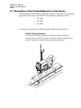
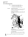
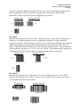
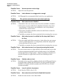
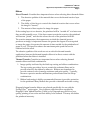
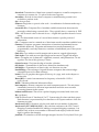
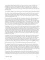
PA/4020 Dual-Panel Printer/Applicator
The PA/4020 Dual-Panel Printer/Applicator combines a tamp
applicator with a secondary wipe-down mechanism. This
mechanism applies a wrap-around label up to 13 inches long to
two adjacent sides of the carton for side/front or side/back
labeling. This unit is functional from either side of the conveyor.
The unique dual-vacuum and slotted-vacuum design delivers a
high degree of label control.
The reliable twin-rod air cylinder [A] tamps the first half of the
label onto the carton as the secondary wipe-down roller [B] wraps
the label around the corner and onto the adjacent side of the
carton.
[A]
[B]
PA/4000 User’s Manual
Section 2, Components
Page 1
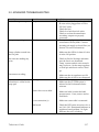
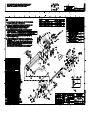
2.0 COMPONENT FEATURES AND SPECIFICATIONS
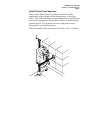
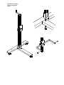
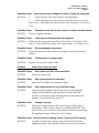
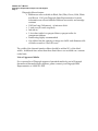
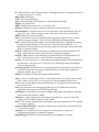
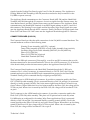
2.1 Floor Stand Assembly
This assembly includes a tee base with
casters [D]; an upright post with a heightadjustable mounting plate [B]; a yoke [C];
and a crank handle for adjusting the
height [A]. The stand can be bolted to the
floor for stability. The bolting holes are
located on the t-base [E].
[A]
[B]
[C]
[E]
[D]
[E]
[E]
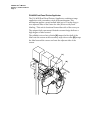
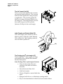
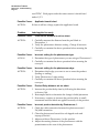
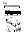
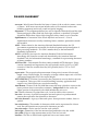
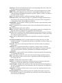
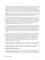
2.2 The Main Unit
The PA/4000 main unit is a robust, yokemounted design of aluminum and steel.
It swivels to conform to common
application orientations – top down, side
panel and bottom up – and then locks in
place. It accommodates different sizes of
[A]
tamp cylinders for variable distance and
variable label size applications. It
provides easy access to configuration
controls – switches, air control, print
engine and sensor adjustments. This unit
connects to almost any computer through
either the RS-232C or the RS-422 serial
interface. It has three main components:
• The air control unit [A]
• label supply and rewind hubs [B]
• Prodigy PlusTM print engine [C].
[B]
[B]
[C]
PA/4000 User’s Manual
Section 2, Components
Page 2
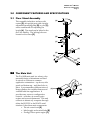
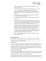
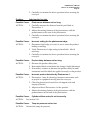
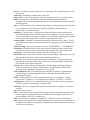
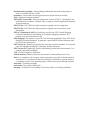
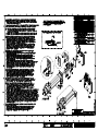
The Air Control Unit [A]
The air control unit regulates the vacuum,
air assist and tamp pressure. The vacuum
holds the label against the tamp pad prior
to application. The air assist guides the
label (as it comes off the peel blade) on to
the tamp pad. The tamp pressure controls
how much air goes into the cylinder
(between 20-40 psi is the usual range).
[A]
Label Supply and Rewind Hubs [B]
The Label Supply Hub holds the roll of
labels in place while the Label Rewind
Hub collects the label backing material
once the label is peeled off.
[B]
[B]
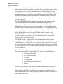
The Prodigy plusTM print engine [C]
The Prodigy PlusTM print engine is a highperformance direct thermal and thermal
transfer label printer.
Some Prodigy PlusTM print engine features:
• Clear side door that allows for
viewing of the label and ribbon
functions.
•
Internal time and date clock
•
Label feed counter
•
Choice of English or metric label data
input.
•
Equipped with die cut, or blackstripe sensing media.
•
Easy-to-load mechanism for label stock and transfer ribbon
[C]
PA/4000 User’s Manual
Section 2, Components
Page 3
•
All popular bar codes and nine different alphanumeric fonts
resident in memory.
•
The 0.0049 inch print element prints high-density bar codes and
easy-to-read characters at 203 dot-per-inch resolution. In
addition, the pixel size can be multiplied by 2 in the horizontal,
and 3 in the vertical direction producing even larger label
formats.
•
Optional memory and font modules programmable using HP
LaserJet1 II (PCL-4) compatibility
•
Dot-addressable graphics function; compatible with PCX, IMG
file formats
•
User selectable and software-selectable print speeds and form
dimensions. Prints at speeds of up to 6 inches per second (152.4
mm/sec.) with maximum print quality. In After BurnerTM mode,
print speeds of 8 inches per second (203.2 mm/sec.) can be
attained for some formats with only a minor reduction in print
quality. Print area is 4.1 inches W x 10.0 inches L (104 mm x
254 mm). It has an innovative dot-history control circuit, called
SEAQTM (Sequential Energy Adjustment for Quality) which
provides exceptional quality while printing at high speeds. This
circuit monitors the printed data and automatically adjusts to
provide maximum printhead performance.
•
Allows for adjusting printhead temperatures (darkness), print
speeds and slew rates.
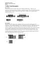
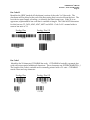
Resident Bar Codes
The Prodigy Plus print engine has all popular bar codes resident in
memory and can print adjacent human readable characters. It has userselectable bar code ratios and heights.
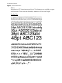
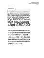
Resident Fonts
There are nine different size built-in alphanumeric fonts. Font multiplication
allows you to print 0.035 inch H (0.9 mm) to 16.0 inches H (406.4 mm). These
fonts include OCR-A, OCR-B (size and character set III), and the ninth one, a
CG TriumvirateTM smooth font, contains 10 different font sizes. All the fonts
can be printed in four different directions.
Optional Memory Modules
There is three optional Memory modules that provide storage for fonts, label
formats, and graphic images. These modules are available in RAM, Flash and
ROM FONT versions (512K available in RAM only).
256K RAM Memory Module: This module should be used in any application
that requires fonts not resident in the printer (i.e.True Type fonts) or for the
PA/4000 User’s Manual
Section 2, Components
Page 4
direct connect download of a label format (label formats can also be stored
and recalled from RAM modules) or graphics (logos). Graphics can be loaded
using programs with an image download function. The loading of images
can also be done with minimal programming on most host computers. Single
font bitmaps, images, or formats cannot be deleted individually. The entire
module must be cleared and data reloaded. This module can be installed in
either slot A or B. This is a volatile memory (temporary storage) and will be
lost at power down.
256K Flash ROM Module: This module provides the same features as the
RAM modules with the added benefit of permanent storage. Typical
applications for a Flash module include downloadable soft fonts, graphics,
and label format storage for use with host computers. This module must be
installed in slot A when being loaded with data. Once it is programmed they
can be installed in either slot A or B. There is a copy command available for
duplicating ROM modules. When using this feature, the source module
should be installed in the B slot, and the blank module in the A slot. A
WRITE PROTECT switch on the Flash module can protect data stored on the
module from being overwritten or erased. This module is a non-volatile
memory, data is stored permanently.
512K RAM Module: This module is used primarily when label formats
exceed 10 inches in length. When this module is in the A slot, the dot memory
is double (from 10” to 20” at 203 dpi). The upper half of memory is reserved
for long label length formatting and the bottom half functions the same as the
256K RAM module. This is a volatile memory (temporary storage) and will be
lost at power down.
Optional Font Modules
There are six optional 512K byte ROM FONT modules available. They are:
1.
2.
3.
4.
5.
6.
CG Triumvirate Bold
CG Triumvirate Italic
CG Times
CG Times Bold
Futura Extra Bold Condensed
Plantin
Each ROM Font module comes with documentation detailing the type and
sizes available on the module and the font number of each size used in the
label formatting. ROM Font modules are programmed at the factory and
cannot be modified for any other purpose. ROM Font modules will operate in
either the A or the B slot.
PA/4000 User’s Manual
Section 2, Components
Page 5
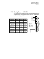
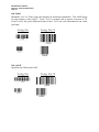
Module Slot locations
The PA/4000 Printer/Applicator has
two module slots in the rear of the print
engine for use with optional memory
modules and font modules. The upper
slot is referenced, as “A” [A] and the
lower slot is “B” [B].
[A]
[B]
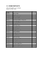
Print Engine Specifications:
Print Engine
Print Method
Maximum Print Speed
Print Resolution
Media Dimensions,
Min.
Media Dimensions,
Max.
Roll Capacity
Fonts
Bar Codes
Flexibility
Memory Module
Option
Communications
Data Transmission
TM
Prodigy Plus
Direct thermal or thermal transfer
6 inches/second with afterburner speeds up to 8
inches/second
203 dots per inch
1” x .25” (25.4 mm x 6 mm)
4” x 13” (101.6 mm x 330 mm)
13” (330 mm) outer diameter
Nine internal fonts. American and European,
uppercase and lowercase with descenders. Six
optional font modules available.
UPC-A/E, UPC-E, EAN-8, EAN-13, Code 39, I 2/5,
Code 128, Codabar, MSI, 2/5, Code 93, Bookland.
Rotation of bar codes and text in four 90 degree
steps; character expansion horizontally and vertically
to 12X; RAM storage for special characters, dotaddressable graphics; sequential numbering.
Three optional memory modules available: 256K
RAM, 256 Flash ROM, and 512K RAM.
RS-232 (300 ! 19,200 bps, Ready/Busy and
X-ON/X-Off)
ASCII
PA/4000 User’s Manual
Section 2, Components
Page 6
Print Engine Programming and Support
Programming and support for the print engine is available from Datamax.
Software
Performance SeriesTM. Diagraph supports Performance
SeriesTM (Premier, Express or Flash) as the software
solution for label creation and printing on the PA/4000.
Windows Drivers. Datamax provides print drivers
through its web site for users who want to print labels
from word processors such as Microsoft Word or Word
Perfect. These drivers provide compatibility for
Windows-based applications but do not take the place
of a dedicated label creation and printing program.
Manuals
Datamax Programmers Manual. Datamax provides a free
programmer’s manual in pdf format through its web
site. This manual explains how to use Datamax
Programming Language (DPL) to write programs for
Datamax printers that create label formats and control
the operation of the printer.
Address
Datamax World Headquarters
4501 Parkway Commerce Boulevard
Orlando, Florida USA 32808
(407) 578-8007
Datamax Tech Support Hotline – (407) 523-5540
Internet
http://www.datamaxcorp.com
PA/4000 User’s Manual
Section 2, Components
Page 7
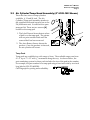
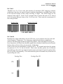
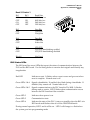
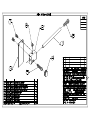
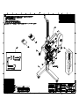
2.3 Air Cylinder/Tamp Head Assembly (6” 6105-180 Shown)
There are three sizes of tamp cylinders
available: 6, 12 and 18 inch. The Air
Cylinder/Tamp pad Assembly attaches to
the extended horizontal support bar on the
PA/4000 main unit. It comes with a spare
tamp pad kit. There are two sensors [A]
located on the tamp pad:
1. The Label Present Sensor detects when
a label is on the tamp pad. The printer
will not print another label until the
current label has been removed.
2. The Auto-Retract Sensor detects the
product. Once the product is detected,
the air cylinder will retract.
[A]
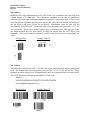
Tamp Pads
Tamp pads are available in a wide range of sizes. The available range runs from
4”x 2” up to 7”x 13” with ¼” increments along the way. As shown below, the
part numbering system for these pads includes the size of the pad in the number:
For example, the part number for a tamp pad using a four-inch wide by two-inch
long label is 6150-223-4000200.
Call Diagraph for pricing and availability.
PA/4000 User’s Manual
Section 2, Components
Page 8
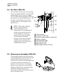
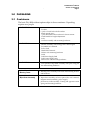
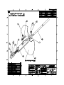
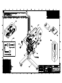
2.4 Air Filter 7505-103
The PA/4000 Air Filter takes the incoming
factory air supply and filters out impurities
and moisture to give a clean, air supply.
The PA/4000 must be supplied with 95-120
[A]
psi of clean, dry, and unlubricated air. The
air filter comes with the system and is
H]
equipped with an OSHA approved air
shut-off valve.
[G]
NOTE: The air filter will drain
out any moisture that has
collected while the air was
disconnected. It is recommended
that the air be shut off when the
unit is turned off. If excessive
moisture builds up, the supply
for incoming air should be
checked. An air dryer should be
installed in the compressed air
supply system if too much water
condensation is present.
[C]
[D]
[F]
[E]
[A] Factory air input
[B] Air output to main unit
[C] 40 micron element within a metal bowl
[D] Moisture indicator
[E] Semi-automatic drain
[F] Air is Closed or OFF
[G] Air is Open or ON
[H] OSHA approved shut-off valve
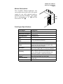
2.5 Photosensor Assembly 5700-216
This assembly includes a diffuse-type selfcontained photosensor with a ten foot cable
and multi-position bracket mounts. It
functions as a switch to start the application
cycle when it detects the presence of a
product on the conveyor. It senses the
presence of a product by receiving LED
radiation reflected from a product surface.
Adjust the sensing distance of the
photosensor with the potentiometer at the
rear of the photosensor.
[B]
PA/4000 User’s Manual
Section 2, Components
Page 9
2.6 Hand-Held Terminal
6105-260
The PA/4000 terminal is a hand-held device, designed
for industrial environments that allows you to control
all of the applicator functions needed to print and
apply labels.
It has a LCD (Liquid Crystal Display) with a one line by
sixteen character text display. The four LEDs show
power on and warn of error conditions. The seven
control keys are described in Section 5.2.
The hand-held terminal communicates with the
PA/4000 main unit through an RJ-11 cable that connects
to J1 on the electrical panel on the back of the print
engine (see Section 4.12). It sits in its holster attached to
the yoke when not in use. See Section 5.2 for more
information on configuring print applications with the
Hand-Held Terminal.
PA/4000 User’s Manual
Section 2, Components
Page 10
2.7 Optional Components
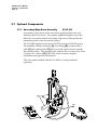
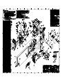
2.7.1 Secondary Wipe-Down Assembly
6105-103
A secondary wipe-down unit is used when applying labels onto two
adjacent panels of a carton. The primary applicator applies part of the
label onto one surface and the secondary wipe-down roller pushes the
unattached portion onto the second surface.
The PA/4000 supplies both electric (24 VDC) and air (0-100 PSI) power.
The assembly includes bracketry [A]; a tee fitting [B]; an interconnect
cable [C] and a photosensor [D] that acts as the signal source to initiate
the cylinder stroke. This assembly also includes the Secondary Wipe-Down
Assembly User’s Manual [E] (5802-930) which contains complete
installation and operation instructions.
This unit comes bundled with the PA/4020 or can be purchased
separately.
[A]
[B]
[C]
[D]
[E]
PA/4000 User’s Manual
Section 2, Components
Page 11
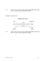
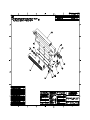
2.7.2
Warning Tower
6150-320
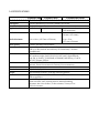
The warning tower assembly provides visual feedback when error
conditions occur. This assembly includes the tower, the mounting
hardware and a signal cable.
[A]
[B]
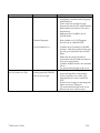
CONDITION
GREEN
YELLOW
RED
[C]
Label Low
Solid
Flashing
OFF
Ribbon Low
Solid
Flashing
OFF
Label Out
OFF
OFF
Flashing
Ribbon Out
OFF
OFF
Flashing
Printer Paused
Flashing
Solid
OFF
Cylinder Error
OFF
OFF
Flashing
Printer Error
OFF
OFF
Flashing
[A] Red
[B] Yellow
[C] Green
`
PA/4000 User’s Manual
Section 3, Packaging
Page 1
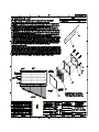
3.0 PACKAGING
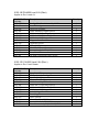
3.1 Containers
The basic PA/4000 without options ships in three containers. Unpacking
requires two people.
CONTAINER #1
CONTAINER #2
CONTAINER #3
Optional Container
Warning Tower
Optional Container
Wipe-Down Assembly
1
2
1
1
1
1
1
Tee base
¾ inch x 5 inch bolt with flat washer
Stand upright piece
¾ inch bolt with washer and nut for chassis mount
Crank handle for height adjustments
Yoke
Air filter assembly with mounting hardware
1
1
1
1
1
1
1
1
1
Chassis Assembly with Prodigy PlusTM Print Engine
PA/4000 User’s Manual
Power Cord
Hand-Held Terminal
Holster with mounting hardware
Cable
Label Inner Supply Disk
Label Outer Supply Disk
Photosensor with mounting hardware
1 Air Cylinder/Tamp Head Assembly with spare tamp pad
kit and mounting hardware
1 Warning tower assembly with cable and mounting bracket
and hardware
1 Wipe-down assembly, air hose, spare roller, user’s manual,
magnetic switch assembly, power supply,
photosensor/cable assembly, T-fitting and opposite torsion
spring and mounting hardware
PA/4000 User’s Manual
Section 4, Installation
Page 1
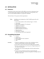
4.0 INSTALLATION
4.1 Overview
Instructions in this section show the PA/4000 in a top down configuration, that
is with the print engine upright and labels applied on top of the product. The
size of the PA/4000 necessitates two people for installation.
Review Section 1.1 for power and air requirements.
Tools:
Installation and configuration of the PA/4000 requires the tools
listed below:
•
•
•
•
•
•
•
•
•
•
Set of socket wrenches with a socket as big as 1 1/8 inch
Utility knife
Sets of Allen wrenches, U.S. and metric
Phillips #1 screwdriver
Phillips #2 screwdriver
Small slotted tip screwdriver
Medium slotted tip screwdriver
Diagonal cutters
9/16 inch box wrench
15/16 inch open-end wrench (optional)
4.2 Assembling the Stand
Parts:
Assembly:
1
1
1
1
1
Tee base
Upright post
Nut for upright to base connection
Crank handle
Yoke
1. Position the upright post on the tee base and tighten in place
with the nut, flat washer and lock washer provided.
2. Lock casters to prevent the stand from rolling during assembly.
3. Place the crank handle on top of the post for height adjustment of
the yoke mounting plate.
4. Attach the yoke to the mounting plate with the washer and nut
provided.
5. Once the unit is positioned on the line for print and apply
operation, bolt the unit to the floor through the 3 holes provided on
the t-base of the stand.
PA/4000 User’s Manual
Section 4, Installation
Page 2
PA/4000 User’s Manual
Section 4, Installation
Page 3
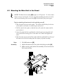
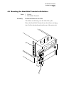
4.3 Mounting the Main Unit to the Stand
NOTE: The Main Unit assembly [B] weighs over 150 pounds. It is best to have
help to connect it to the yoke. Exercise care when attaching the main unit to the
yoke to avoid bending the air assist tube [C] at the bottom of the print engine.
Tips for attaching the main unit to the yoke by yourself:
1. Place the main unit on a work surface. The surface should allow for the base
of the stand to roll under it so that the post can touch it.
2. Roll the stand to the surface so that the base rolls under the surface and the
post touches it.
3. Lower the stand with the crank handle so that the yoke mounting bolts [A]
line up with the mounting holes on the main unit. Attach and tighten the
bolts.
4. Raise the main unit up and off the surface with the crank handle on the top of
the stand and roll the unit away from the surface for further assembly.
Parts:
Assembly:
1
PA/4000 main unit [B]
1. Attach the main unit to the yoke with bolts provided [A].
2. Make sure the yoke/main unit assembly is level and secure
before proceeding.
[B]
[A]
[C]
PA/4000 User’s Manual
Section 4, Installation
Page 4
4.4 Mounting Attachments to the Main Unit
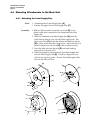
4.4.1 Attaching the Label Supply Disc
Parts:
Assembly:
1
1
Aluminum Rear Label Supply Disc [A]
Smokey Plexiglass front Label Supply Disc [F]
1. With an Allen wrench, loosen the set screw [D] on the
plastic collar that is attached to the aluminum rear label
supply disc.
2. Slide the aluminum rear label supply disc [A] (with the
collar facing toward you) onto the label supply hub. The
label sensor slot [C] on the disc allows the label low sensor
[B] to sense when the label roll gets low. After the disc is in
position tighten the set screw [D] with an Allen wrench,
3. Load the label roll onto the hub [E] (see label loading
instructions in Section 4.13).
4. Slide the plexiglass smoke-colored front label supply disc
onto the label supply hub [E]. It will be a tight fit so you
will need to tap it in gently. Be sure that the flanged collar
fits into the label roll core.
[A]
[D]
[B]
[C]
[E]
[F]
PA/4000 User’s Manual
Section 4, Installation
Page 5
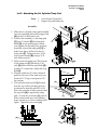
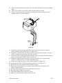
4.4.2 Attaching the Air Cylinder/Tamp Pad
Parts:
1
1
Air Cylinder/Tamp Pad
Support bar and hardware
Assembly:
1. Slide the air cylinder/tamp pad assembly
onto the extended horizontal support bar
[A] on the PA/4000 main unit.
2. Position the assembly so the tamp pad
[C] rests 3/16 inch [D] from the peel
blade [E] on the print engine. Before
you tighten the assembly into position,
manually extend the tamp pad [C] to
make sure that it will not hit the air
assist tube [F]. Tighten the two 10-32
socket head screws [B] using a 3/32
inch Allen wrench.
3. Fully retract the tamp pad. The bottom
of the tamp pad [C] should be 1/16
inch [G] lower than the peel blade [E]
position. To attain this, adjust the stop
bolt [H].
4. Plug the cable into J5 of the electrical
panel on the rear of the main unit, see
Section 4.12. Plug in and power ON
the system.
5. The cylinder home switch [I] (located
near the top of the cylinder) must be
positioned so that the red LED is ON
when the cylinder is fully retracted and
the stop bolt [H] is against the tamp
pad. Loosen the set screws [J] with an
Allen wrench and move the cylinder
home switch up or down until the LED
lights. Tighten the set screws [J].
[A]
[B]
[D]
[E]
[C]
[G]
[F]
[H]
[I]
[J]
PA/4000 User’s Manual
Section 4, Installation
Page 6
4.5 Air Tube Connections
Parts:
Assembly:
1 1/4 inch clear air tube marked “VAC”
1 1/8 inch clear air tube marked “AIR ASSIST”
1 1/4 inch clear air tube marked “TOP”
1 1/4 inch clear air tube marked “BOTTOM”
Vacuum Tube Connection
Connect the 1/4 inch clear air tube marked "VAC" [C]
to the brass vacuum input located on the tamp pad.
Air Assist Tube Connection
Connect the 1/8 inch clear air tube marked "AIR
ASSIST" [B] to the input located on the blow tube of the
print engine.
[A]
[D]
[B]
[C]
Air Cylinder Top
Connect the 1/4 inch clear air tube marked "TOP" [A]
to the input located on the top of the air cylinder.
Air Cylinder Bottom
Connect the 1/4 inch clear air tube marked "BOTTOM"
[D] to the input located on the bottom of the air cylinder.
NOTE: See Section 5.4 for configuration of the air cylinder/tamp pad.
PA/4000 User’s Manual
Section 4, Installation
Page 7
4.6 Mounting the Hand-Held Terminal with Holster
Parts:
Assembly:
1
1
Holster
Hand-Held Terminal
Mount the Holster to the Yoke
The holster can be hung over the side of the yoke.
Place the Hand-Held Terminal into the holster and plug
into J1 of the electrical panel on the rear of the main unit.
PA/4000 User’s Manual
Section 4, Installation
Page 8
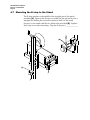
4.7 Mounting the E-stop to the Stand
The E-stop attaches to the middle of the upright part of the stand
assembly [A]. Remove the E-stop cover and use the opened box for a
template for drilling the two holes needed to bolt it to the stand.
Secure it to the stand with the two Allen bolts provided [B]. Replace
the E-stop cover after mounting. Plug the E-stop into ______________
[B]
[A]
PA/4000 User’s Manual
Section 4, Installation
Page 9
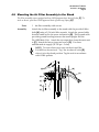
4.8 Mounting the Air Filter Assembly to the Stand
The filter assembly comes equipped with an OSHA approved air shut-off valve [F]. To
turn on the air, push the OSHA approved shut-off valve up (Open) [D].
Parts:
Assembly:
1
Air filter assembly with screws
Attach the air filter assembly to the stand with the provided Allen
bolts [A] using a 3/16 inch Allen wrench. Attach the ground cable
from the main unit to the screw indicated at [B]. This ground cable
provides ground bonding between the stand upright and the
PA/4000 Main Unit. Attach the air output hose from the main unit
to [C]. Attach the factory input air hose to [G]. Use clean
unlubricated air supply (95-120 psi – 3 cfm).
NOTE: To warn others not to turn on the air until the
PA/4000 can be serviced, “Tag“ the air shut-off valve [E]
when it is in the closed position. Tag the unit in accordance
with OSHA policies.
[A]
[B]
[C]
[G]
[F]
[D]
[E]
PA/4000 User’s Manual
Section 4, Installation
Page 10
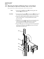
4.9 Mounting the Optional Warning Tower to the Stand
If your system does not have a warning tower, move to the next section.
Parts:
Assembly:
1 Warning Tower [A] with cable [D], mounting plate and
hardware [B] (P/N 6150-320)
1. Screw the mounting plate [B] onto the stand [E] with the 1/4
inch Allen bolts provided using a 3/16 inch Allen wrench.
2. Loosen the cable grommet and the adjacent nut on the end
of the warning tower. Let the grommet and nut slide
down the cable.
3. Holding the tower upright, pass the tower through the slot
in the mounting plate [B]. Tighten the nut under the
mounting plate and re-attach the cable grommet.
4. Plug the DB9 plug into connection J4 on the electrical panel
on the back of the print engine [C] (see Section 4.12) and
hand tighten the jackscrews.
[A]
[B]
[C]
[D]
[E]
PA/4000 User’s Manual
Section 4, Installation
Page 11
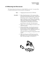
4.10 Mounting the Photosensor
The distance between the photosensor and the PA/4000 is not crucial. A good guideline
is to place the photosensor as close as possible to the applicator.
Parts:
Assembly:
1
Diagraph photosensor kit P/N 5700-216
1. Mount the photosensor to the conveyor using
the bracket and hardware provided. Position the
photosensor where it will not be tripped by the
next product prior to completion of the product
delay on the first product. Improper positioning
will result in missed products. Adjust the
sensing distance of the photosensor with the
potentiometer at the rear of the photosensor.
2. Tighten screws with a Phillips screwdriver and a
5/16-inch wrench.
3. Measure the distance from the photosensor to
the peel blade on the print engine and record
this measurement on the PA/4000 Configuration
sheet, see Section 6. You will need this
information later during the configuration of this
system.
4. Make sure the power is OFF and connect the
photosensor to J2 on the electrical panel on the
back of the print engine, see Section 4.12.
PA/4000 User’s Manual
Section 4, Installation
Page 12
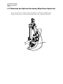
4.11 Mounting the Optional Secondary Wipe-Down Applicator
If your system has a secondary wipe-down applicator, follow the installation and
operation instructions in the Secondary Wipe-down User’s Manual (5802-930).
PA/4000 User’s Manual
Section 4, Installation
Page 13
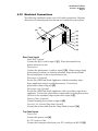
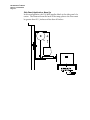
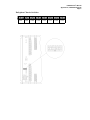
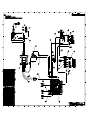
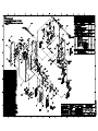
4.12 Electrical Connections
The following installation notes cover ALL cable connections. Skip any
directions for connecting devices that are not included in your system.
[B]
[A]
[C]
[D]
[E]
[F]
[G]
[H]
Rear Panel Inputs
Hand-Held Terminal
Connect the RJ-11 cord to input J1 [C]. Place the terminal in its
holster when not in use.
Photosensor 1
Connect the photosensor 1 cable to input J2 [D]. When using a single
photosensor, position it so that the secondary wipe-down cylinder
has actuated prior to the next photosensor trip.
Photosensor 2 (Optional)
For the PA/4020 Dual Panel Applicator with the secondary wipedown applicator using a second photosensor. Connect the
photosensor cable to input J3 [E].
Photosensor Out (Optional)
For the PA/4020 Dual Panel Applicator with a secondary wipe-down
applicator. Connect the photosensor output cable from the photosensor
out slot on the secondary wipe-down unit to input J6 [F].
Warning Tower (Optional)
Connect warning tower cable to input J4 [G].
Sensor for Air Cylinder/Tamp Head Assembly
Connect the sensor cable from the Tamp Head to input J5 [H].
Top Panel Inputs
Power Cord
Connect the power cord [A].
Rs-232 Computer Cable
Connect the computer cable from your PC’s serial port to RS-232 [B].
PA/4000 User’s Manual
Section 4, Installation
Page 14
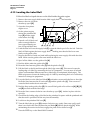
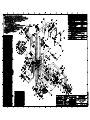
4.13 Loading the Label Roll
Follow the label web path shown on the label inside the print engine.
1. Remove the outer supply disk from the label supply hub [F] and set aside.
2. Remove the wire clip from
[E]
the take-up spool [H].
[F]
[G]
3. Open the clear printer
engine cover.
4. On the printer engine,
[A]
release the printhead lift
lever [E] and the pinch
roller release lever [I].
[H]
PRINTHEAD
MOUNT
ASSEMBLY
[C]
5. Unpack a roll of labels and
remove enough labels to
leave approximately two
feet of exposed label liner.
[M] [L] [K] [J]
[B]
[D]
[I]
6. Load the label roll onto the supply hub [F] so that the labels spool off to the left. Push the
label roll flush against the inner supply disk [G] making sure that the label core seats
firmly on the guide collar.
7. Support the label roll with one hand while replacing the outer supply disk with the other
hand. Make sure the guide collar seats inside the label core.
8.
9.
10.
11.
Spool off the labels over the guide roller [A].
Feed the labels under the guide roller [B].
Route the liner between guide roller [C] and the pinch roller [J].
Pull the labels to the left and through the label edge sensor [K]. This sensor locates the
leading edge of a label, by measuring the level of opaqueness. You can move it left and
right to accommodate different activators (label edge or backprinted, black stripe). The
black stripe sensor locates the leading edge of a label by measuring the level of reflectivity
instead of a change in opaqueness.
12. Loop the labels over the label peel blade [M] and make a u-turn with the liner to the right.
Route the liner between the air assist tube [L] and the pinch roller [J]. Take care not to
route the labels under the air assist tube.
13. Feed the liner under guide roller [D]. Be sure all label guide roller collars on [A], [B], [C]
and [D] are flush with the label edge.
14. Route the liner counter-clockwise onto the take-up spool [H]. Anchor in place with the
wire clip.
15. Check that the leading edge of the label at the printhead is square with the printhead and
that the stock is positioned all the way into the assembly.
16. Lock down the printhead lift lever [E].
17. Turn the label take-up spool [H] counter-clockwise very gently (liner tears easily) until
there is no slack in the liner between the peel blade [M] and the pinch roller [J]. While
maintaining the tension in the liner, engage the pinch roller release lever [I].
18. Press the FEED key on the Hand-Held Terminal.
PA/4000 User’s Manual
Section 4, Installation
Page 15
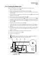
4.14 Loading the Ribbon Roll
Follow the diagram of the ribbon path inside the print engine cover.
1. Raise the printhead lift lever [A].
2. Remove remaining ribbon from the ribbon rewind roller [C].
3. Unwrap ribbon roll from the package. Do not remove the ribbon leader and the
adhesive edge.
4. Slide the ribbon roll completely onto the ribbon supply hub [D] so that the ribbon
leader feeds off to the left.
5. Feed the leader to the left under the ribbon idler [E].
6. Pass the leader under the printhead mount assembly. Be sure the ribbon passes
through the center of the ribbon sensor [F] and above the label edge sensor [G].
7. Pull the leader through, past the ribbon shield [H], and over the top of the ribbon
idler roller [B].
8. Pull the leader to the ribbon rewind roller [C].
9. Anchor the leader to the rewind roller [C] with either the clasp or the adhesive
edge on the leader. Securing with the adhesive edge requires an empty ribbon
fiber core.
10. Wind the leader counter-clockwise onto the rewind roller [C]. Continue until all
of the leader wraps onto the rewind roller [C] and only the ribbon is exposed
(approx. 12 turns).
11. Make sure that the ribbon is feeding smoothly along its path.
12. Lock down the printhead lift lever [A].
13. Close the print engine cover.
NOTE: Clean the printhead every time you replace the ribbon to
maintain print quality and extend printhead life.
[A]
[B]
[C]
PRINTHEAD
MOUNT
ASSEMBLY
[H] [G] [F]
[E]
[D]
PA/4000 User’s Manual
Section 4, Installation
Page 16
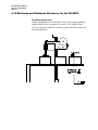
4.15 Minimum and Maximum Distances for the PA/4000
Top Down Application
In this configuration, the PA/4000, with a 6 inch tamp cylinder,
applies labels to the top panel of a carton. The height of the
conveyor plus the tallest box must be greater than 10 inches and
less than 48 inches.
PA/4000 User’s Manual
Section 4, Installation
Page 17
Side Panel Application, Nose Down
In this configuration, the PA/4000 applies labels to the side panel
of a carton. For this setup, the height of the conveyor must be
greater than 22 inches and less than 58 inches.
PA/4000 User’s Manual
Section 4, Installation
Page 18
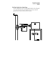
Side Panel Application, Nose Up
In this configuration, the PA/4000 applies labels to the side panel of a
carton. The distance from the back of the tamp plate to the floor must
be greater than 30 ½ inches and less than 62 inches.
PA/4000 User’s Manual
Section 4, Installation
Page 19
Bottom Up Application
In this configuration, the PA/4000 applies labels to the bottom panel of
a carton. The distance from the tamp plate to the floor must be greater
than 30 inches and less than 65 inches.
4.16 Final Positioning
1. Disconnect power cords and the air line if they will hinder the
movement of the PA/4000.
2. Unlock casters.
3. Carefully push the PA/4000 into its position next to the conveyor.
4. Bolt the PA/4000 to the floor through the holes in the t-base.
5. Make necessary connections such as power cords, airline and
photosensor cable.
PA/4000 User’s Manual
Section 5, Configuration
Page 1
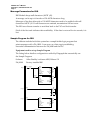
5.0 CONFIGURATION
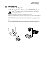
5.1 Power Module Configuration
5.1.1 Configuring the Power Module for the 110/120VAC Application
!
Failure to use proper fuses and/or install the fuse assembly for correct voltage
can damage the PA/4000.
Disconnect the power cord before servicing the power module.
Pop the fuse assembly up and out of the power module with a flat head screwdriver.
Once out of the power module, turn the fuse assembly so that the arrow on the
110/120VAC side of the assembly is lined up with the arrow on the power module.
Replace the fuse assembly.
See Fuse Replacement Kit Instructions 6105-383N when needing to replace a fuse.
PA/4000 User’s Manual
Section 5, Configuration
Page 2
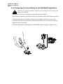
5.1.2 Configuring the Power Module for the 220/240VAC Application
!
Failure to use proper fuses and/or install the fuse assembly for correct voltage can
damage the PA/4000.
Disconnect the power cord before servicing the power module.
Pop the fuse assembly up and out of the power module with a flat head screwdriver.
Once out of the power module, turn the fuse assembly so that the arrow on the
220/240VAC side of the assembly is lined up with the arrow on the power module.
Replace the fuse assembly.
See Fuse Replacement Kit Instructions 6105-404N when needing to replace a fuse.
PA/4000 User’s Manual
Section 5, Configuration
Page 3
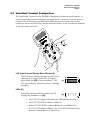
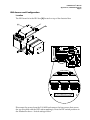
5.2 Hand-Held Terminal Configuration
The Hand-Held Terminal for the PA/4000 is designed for industrial environments. It
controls applicator functions that print and apply labels. It features a one-line sixteen
character text LCD display, four LED lights that show power on and warn of error
conditions and seven control keys that are described below. It sits in its holster attached
to the yoke when not in use.
LCD (Liquid Crystal Display) Menu Window [A]
The LCD menu window displays one-line of text
allowing up to sixteen characters. It displays
menu items (see [D]) or error conditions. “All
OK” screen display means the system is printing
normally.
[A]
LEDs [B]
Four LEDs signal a condition (while the LCD
displays the condition, see [A]):
[B]
POWER
LABEL
RIBBON
ERROR
•
Power LED ON signals all systems go, OFF indicates no power
•
Label LED FLASHING indicates Label Low
•
Ribbon LED FLASHING indicates Ribbon Low or Ribbon Out
•
Error LED ON indicates Ribbon Out, FLASHING indicates Printer
Paused, Cylinder Error or Printer Error
PA/4000 User’s Manual
Section 5, Configuration
Page 4
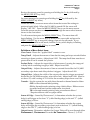
LCD Contrast or Scroll Keys [C]
Hold the 2nd key down while pressing the up or
down arrow keys to control LCD Display
contrast. Up key to increase contrast, down key
to decrease contrast.
LCD
CONTRAST
[C]
These keys are also used to scroll through menu items as discussed in [D].
Menu/Select or Display/Cancel Key [D]
This key is used to toggle between Menu mode and Edit mode.
DISPLAY
CANCEL
[D]
MENU/
SELECT
FE
PA/4000 User’s Manual
Section 5, Configuration
Page 5
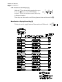
Review the current count (by pressing and holding the 2nd key followed by
the MENU/SELECT key once).
See error messages (by pressing and holding the 2nd key followed by the
MENU/SELECT key twice).
Within the MENU screen are menu select items that control the settings to
print and apply labels. When the PA/4000 is turned ON the screen will
display “ALL OK”. Press the MENU/SELECT key to see the menu screen.
From this screen use the arrow keys to scroll through the menu select items as
shown in the chart above.
To edit a menu item press the MENU/SELECT key. The menu item will
begin flashing. Use the arrow keys to scroll to the correct edit and press the
MENU/SELECT key to accept the change, then exit the edit mode. If you
make a mistake while in edit mode, hold the 2nd key while display is flashing
and press the MENU/SELECT key to cancel.
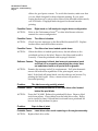
Definitions of Menu Select Items:
Clear Count – Resets the “applied label” counter to zero.
Tamp Dwell – Adjusts the amount of time that the tamp pad stays extended before
retracting to home position. Adjust from 0-100. The tamp dwell time must be set
greater than 30 ms to extend the cylinder.
Product Delay – Adjusts the input delay of photosensor 1 causing the tamp pad
to delay before extending to apply a label. Adjust from 0-999.
Output Delay – Adjusts the amount of time an external device like the PA/4000
secondary wipe-down unit delays before it triggers. Adjust from 0-999.
Output Pulse - Adjusts the width of the output pulse used to trigger an external
device like the PA/4000 secondary wipe-down unit. Adjust from 0-999. Must be
set above 25, with a setting of 25 or lower the secondary wipe-down won’t fire.
Transfer – Sets the system for use with direct thermal or thermal transfer ribbon.
OFF for direct thermal label printing.
ON for thermal transfer printing using a black ribbon. Ribbon sensor
is enabled and head current temperature is reduced.
TR for thermal transfer printing using a translucent ribbon.*
* Requires ribbons with an opaque trailer.
Sensor #1 Edge – Sensed by Photosensor 1, it determines whether the system
delay(s) will trigger at the front “L” (called leading edge) or the end “T” (called
trailing edge) of a box.
Sensor #2 Edge – Sensed by Photosensor 2, it determines whether the output
delay will trigger the secondary wipe-down unit at the front “L” (called leading
edge) or the end “T” (called trailing edge) of a box.
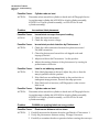
Output Sensor– Determines whether the Output Pulse will be sent through either
Photosensor 1, Photosensor 2 or make No Connection. Choose 1, 2, or NC.
PA/4000 User’s Manual
Section 5, Configuration
Page 6
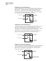
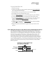
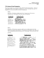
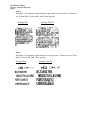
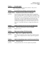
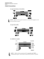
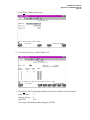
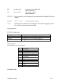
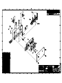
Output Sensor Set to Photosensor 1
With the output sensor set to 1 the output pulse will be sent through
photosenser 1. The drawing below shows the input signal from
Photosensor 1 coming into the PA/4000 triggering the tamp pad,
and with the same signal triggering a secondary device (both using
the same edge of the product, leading or trailing).
1
PHOTOSENSOR 1
NC
INPUT
DELAY
TRIGGERS
TAMP PAD
2
PHOTOSENSOR 2
OUTPUT
DELAY
TRIGGERS
SECONDARY
DEVICE
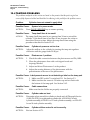
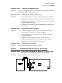
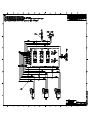
Output Sensor Set to Photosensor 2
In a special situation where the same edge cannot be used, you will
need to use two photosensors. With the output sensor set to 2,
photosensor 1 will trigger the tamp pad while photosensor 2 triggers
a secondary device. The output pulse will be sent through
photosensor 2. The drawing below shows the photosensor input
signals of both photosensors 1 and 2 entering the PA/4000.
1
PHOTOSENSOR 1
NC
INPUT
DELAY
TRIGGERS
TAMP PAD
2
PHOTOSENSOR 2
OUTPUT
DELAY
TRIGGERS
SECONDARY
DEVICE
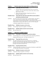
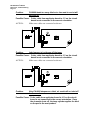
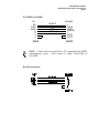
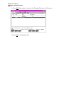
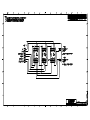
Output Sensor Set to No Connection
In the case where you don’t want the secondary device to be triggered,
set the output sensor to NC (NO CONNECT). As shown below,
Photosensor 1 will trigger the tamp pad but the system sends no
output pulse signal to a secondary device.
1
PHOTOSENSOR 1
NC
INPUT
DELAY
TRIGGERS
TAMP PAD
2
PHOTOSENSOR 2
OUTPUT
DELAY
DOES NOT TRIGGER
SECONDARY DEVICE
PA/4000 User’s Manual
Section 5, Configuration
Page 7
Auto-Retract - Enables or Disables the Auto-Retract feature of the
PA/4000. The Auto-Retract sensor is located on the tamp pad. It senses
the product when the tamp pad extends to apply a label, then commands
the tamp pad to retract to the home position. If the sensor does not detect
a product, or if the sensor is turned OFF from the Hand-Held Terminal,
the cylinder will remain in the extended position until the TAMP DWELL
time has expired.
Darkness – Adjusts the level of darkness (printhead temperature) in a
printhead. It is used to balance a new printhead so that it prints at the
same level of darkness as the previous head. Darkness values are from 1
to 99. Start with a midrange number and work from there.
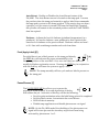
Feed (Apply Label) [E]
APPLY
LABEL
Provided there is not a label present on the tamp pad already,
[E]
the FEED key will advance the paper automatically to the
first print position of the next label. On a new size label, two labels are
usually fed before registration occurs. Pressing the FEED key in conjunction
with the 2nd key will cause the system to apply a label.
NU/
ECT
FEED
NOTE: The tamp assembly will not cycle unless a label is present on
the tamp pad.
Pause/Resume [F]
The PAUSE/RESUME key allows you to pause the
[F]
printing of a run of labels. A second depression of the key
will resume the job. Activation of this key will do the following:
• Stop the print mechanism when the label being printed is completed
• Stop the label counter, but maintain the count balance
• Hold all data in memory
• Disable tamp applicators and disable photosensor out signal
PAUSE/
RESUME
NOTE: On the PA/4020 model, the disabling of the photosensor out
signal will in turn prevent the secondary wipe-down from being
activated by photosensor 1 or 2.
STO
CLE
PA/4000 User’s Manual
Section 5, Configuration
Page 8
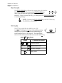
Stop/Clear [G]
The STOP/CLEAR key deletes the current print job from the
[G]
PA/4000's memory. If you press the STOP/CLEAR key
twice, you will clear two print jobs from the PA/4000's
memory. Once you press this key, you must press the PAUSE/RESUME key
to resume printing.
STOP/
CLEAR
USE/
UME
NOTE: Pressing the STOP/CLEAR key will NOT clear any
PA/4000 Error conditions.
2nd Key [H]
The 2nd key works like the shift key on a PC
keyboard. Holding the 2nd key down while pressing [H]
another key accesses new functions eliminating the
need for more keys on the keypad. The chart below
shows all the functions that can be accessed with 2nd key.
Hold
2nd
Key then:
Press
Function Accessed
or
Press Once
Press Twice
FEED
Controlls contrast
MENU/
SELECT
MENU/
SELECT
Review current count
See error messages
Apply a label
2nd
PA/4000 User’s Manual
Section 5, Configuration
Page 9
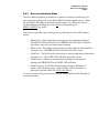
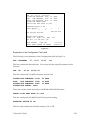
5.2.1
Error or Indications Menu
The Error Menu indicates problems the system is currently experiencing. An
error messages will appear on the Hand-Held Terminal display screen. When
the red Error LED lights on the hand-held terminal, you will need to check
the Error Menu by holding down the 2nd key and pressing the
MENU/SELECT key twice.
There are five possible error messages that could appear on the LDC display
screen:
• Ribbon Out – When the ribbon in the printer is completely depleted,
the RIBBON LED will flash and the ERROR LED will stay lit. Replace
the ribbon, clear the error and resume printing.
• Ribbon Low - The ribbon in the printer is nearly depleted and should be
changed soon. The RIBBON LED will flash when this occurs.
• Label Low - The label stock in the printer is nearly depleted and should be
changed soon. The LABEL LED will flash when this occurs.
• Printer Error – Whenever a mechanical problem has interrupted
printing, the ERROR LED and LABEL LED will flash.
• Printer Paused - The Printer Paused error message will appear if
either of the following occurs: The PAUSE switch is pressed or a
print job is canceled with the STOP/CLEAR key.
To clear an error in the printer, press PAUSE, FEED and then PAUSE again to
resume operation.
PA/4000 User’s Manual
Section 5, Configuration
Page 10
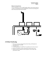
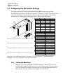
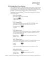
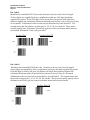
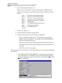
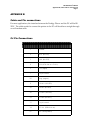
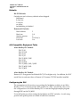
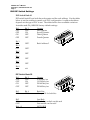
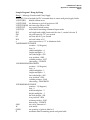
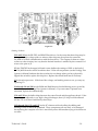
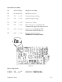
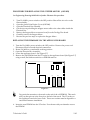
5.3 Configuring the DIP Switch Settings
The eight position DIP Switch block labeled SWS1 [A] is located on top of the
PA/4000 main unit next to the RS-232 connector. Switches 1, 2 and 3 control the baud
rate while switches 4-8 control printer features such as word length, compatibility,
present sensor, ribbon sensor and cutter enable. Refer to the chart below.
[A]
[A]
When operating the PA/4000, this switch should be set to OFF.
When operating the PA/4000, this switch should be set to ON.
When operating the PA/4000, this switch should be set to OFF.
When operating the PA/4000, this switch should be set to ON.
Baud Rate
SW1-1
SW1-2
SW1-3
9600
OFF
OFF
OFF
4800
OFF
OFF
ON
2400
OFF
ON
OFF
1200
OFF
ON
ON
600
ON
OFF
OFF
300
ON
OFF
ON
19200
ON
ON
OFF
TEST
ON
ON
ON
Word Length
SW1-4
8, 1, N-Bit Word
OFF
7, 2, N-Bit Word
ON
Compatibility
SW1-5
Prodigy Plus Offset
OFF
Prodigy Offset
ON
Present Sensor
SW1-6
Disable Sensor
OFF
Enable
ON
Ribbon Sensor
SW1-7
Standard Sensing
OFF
Inverted Sensing (Colored
and Special Ribbons)
ON
Cutter Enable
SW1-8
Remote Cut Enabled
ON
Remote Cut Disabled
OFF
If you have the labeling software Performances Series for WindowsTM recommended by
Diagraph, you can set switches 4 through 8 through it.
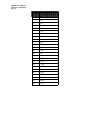
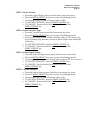
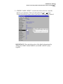
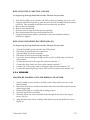
5.3.1
Setting the Baud Rate
Switches 1, 2 and 3 control the PA/4000's baud rate. Before you can send
printed labels to the PA/4000, you need to set the baud rate. The chart above
gives the position of the three switches and the corresponding baud rate for
each setting. Set your switches according to your baud rate.
PA/4000 User’s Manual
Section 5, Configuration
Page 11
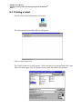
5.3.2 Setting Other Printer Features
The PA/4000 can accept 7 or 8 bit data, while ignoring parity. It also requires
at least 1 stop bit. This configuration assures the greatest compatibility with
most serial devices, even if the data format arrangement of the host cannot be
modified. Set these features manually unless you have Diagraph’s
Performance Series for WindowsTM software (these settings can be set from
inside the software).
SW1-4 Word Length
Switch SW1-4, selects the word length.
SW-4
7-BIT WORD ON
8-BIT WORD OFF
SW1-5 Compatibility
Switch SW1-5 emulates a standard PRODIGY PRINTER. When
operating the PA/4000, this switch should be set to OFF.
SW1-5
Emulate Prodigy ON
PA/4000
OFF
SW1-6 Present Sensor
Switch SW1-6 enables the label present sensor. Setting this switch to
the ON position enables the sensor. Setting this switch to the OFF
position disables the sensor.
SW1-6
Enable sensor
ON NOTE: This switch must be ON!
Disable sensor
OFF
SW1-7 Ribbon Sensor
This switch is always OFF for PA/4000. This switch enables inverse
ribbon sensor logic, which is used for colored ribbons only.
SW1-7
Enable
ON
Disable
OFF*
*Must be turned OFF even when translucent (colored) ribbon is used.
SW1-8 Cutter Enable
This switch controls the cutter function.
SW1-8
Enable Cutter
ON (switch should be left ON)
Disable Cutter
OFF
NOTE: To read the switch settings, the printer must be reset by turning it off and back on.
PA/4000 User’s Manual
Section 5, Configuration
Page 12
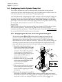
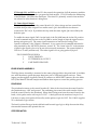
5.4 Configuring the Air Cylinder/Tamp Pad
This section assumes that you have already made all electrical and air pressure
connections and that a label has been sent to the PA/4000 from an outside source; ie:
a PC with Performance Series for WindowsTM Labeling Software.
You will be manually configuring the air flow controls on the air cylinder/tamp pad
to control the force at which the tamp pad is extended and retracted. You will also
be setting various menu select items using the Hand-Held Terminal to tell the tamp
pad when to extend in order to effectively apply a label to the product and how long
the tamp pad will wait before it retracts to the home position.
Preparation
Make sure the conveyor isn’t moving and the air is turned off (OSHA shut-off valve
is in the closed position). Position the PA/4000 next to the conveyor in the
orientation used for production. Power ON the system. Press the PAUSE/RESUME
key on the Hand-Held Terminal to pause the system.
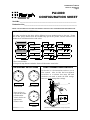
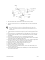
5.4.1 Configuring the Air Flow on the Air Cylinder/Tamp pad
The air flow controls [B] and [C] on the cylinder/tamp pad control the air
pressure needed to cause the tamp to extend and retract fully and with the
appropriate force. Record these final settings on the PA/4000 Configuration
Sheet attached to the PA/4000 (See Section 6). Make sure the cylinder/tamp pad
assembly is properly mounted to the extended horizontal support bar and the
tamp pad is properly positioned with the peel blade as shown in Section 4.4.2.
1. Manually retract the tamp pad.
Ensure the cylinder home switch [A]
LED is lit when the cylinder is fully
retracted. If not, adjust the position
of the sensor by loosening the set
screws and moving the sensor up or
down until the LED comes on.
Retighten the set screws.
[A]
[B]
2. Make sure both the top (retract) [B]
and bottom (extend) [C] Air Flow
Controls are turned fully
counterclockwise.
3. Place a test product on the conveyor
in the stroke path of the tamp pad
just as it will be applying in normal
production.
[C]
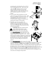
4. Make sure the tamp pad is parallel to
the product. Manually extend the tamp cylinder until the tamp pad contacts
the products surface. If the tamp pad is not completely parallel to the surface of
the product, retract the tamp pad slightly, loosen the yoke bolt [D] on the
PA/4000 User’s Manual
Section 5, Configuration
Page 13
mounting plate and adjust the yoke until it is
level and retighten the bolt. Then loosen the
yoke bolts [E] holding the main unit and
adjust the main unit until it is level and
retighten the bolts. This will make the tamp
pad completely parallel to the product
surface.
[D]
5. For now, move the test product out of the
path of the tamp pad but keep it nearby. With
the tamp pad fully extended, slowly turn the
crank handle on the stand to lower the
PA/4000 until the tamp pad extends about 1
inch past the surface of the product.
6. Manually return the tamp pad to the
cylinder’s fully retracted position and turn
ON the air supply. To begin with, adjust the
tamp air pressure [F] to 25 psi (between 20-40
psi is the usual range).
!
CAUTION: DO NOT PLACE YOUR
HAND BETWEEN THE PA/4000
MAIN UNIT AND THE TAMP PAD.
7. Press PAUSE-RESUME on the Hand-Held to
resume the air cylinder/tamp pad action. This
triggers the cylinder/tamp pad to cycle. Adjust
the psi until the tamp pad appears to extend equal
to the surface of the test product. Replace the test
product back into the path of the tamp pad.
Notice the force the tamp pad extends and
retracts.
[E]
[F]
8. Press PAUSE-RESUME again to pause the cycling
action. To attain the proper force of the air cylinder/tamp pad extension and
retraction, adjust the top [B] and bottom [C] air flow controls by turning
clockwise one full turn at a time. Count how many full turns are made to get
the right amount of force necessary considering the product, label size, etc.
Record the turns on the PA/4000 Configuration Sheet (see Section 6). You may
have to readjust the tamp air pressure [F] to get the correct amount of air
pressure. When you are satisfied with the psi and air flow settings, go to the
next section on setting the tamp dwell.
PA/4000 User’s Manual
Section 5, Configuration
Page 14
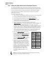
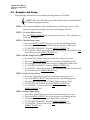
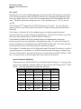
5.4.2
Setting the Tamp Dwell with the Hand-Held Terminal
The Tamp Dwell Menu Select Item on the Hand-Held Terminal adjusts the
amount of time that the cylinder waits before returning to its home position.
A lower Tamp Dwell value setting will reduce the time that the cylinder
waits and because the cylinder extension time is shorter, the cylinder's
stroke may be shorter.
To set the Tamp Dwell value:
1. Turn on the air by sliding the OSHA shut-off valve to the ON position.
2. Using the Hand-Held terminal, turn off the auto-retract.
3. On the Hand-Held Terminal press the MENU/SELECT key.
4. From the Menu screen, press the down arrow key twice until the
display shows the Tamp Dwell screen.
5. Observe the current Tamp Dwell value by pressing the
MENU/SELECT key to enter the Edit mode (the value will flash). To
begin with, set the Tamp Dwell value to 30. Note: A six inch
cylinder with a three inch tamp distance at 40 PSI completes its cycle
in about 0.235 seconds. Tamp cycle times are dependant on air flow
control, tamp air pressure psi and photosensor distance. Note the air
flow control instructions in Section 5.4.1. Tamp Dwell settings and
cycle time times for the PA/4000 are in the following chart:
6. Press the MENU/SELECT key to save
the new value. The value you enter will
not be used until the MENU/SELECT
key is pressed and the display is no
longer flashing. Hold the 2nd key and
press the MENU/SELECT key while the
display is still flashing to CANCEL.
7. Observe how far the cylinder extends
before it retracts. Use the arrow keys to
increase the DWELL value so that the
cylinder extends but does not reach the
product. Turn on the conveyor. Adjust
the Tamp Dwell setting until labels are
reliably applied to every product.
Record the final dwell value on the
PA/4000 Configuration Sheet. See
Section 6.
Tamp
Dwell
Setting
10
20
30
40
50
60
70
80
90
100
Complete
Cycle
Time in
Seconds
0.13
0.26
0.39
0.52
0.65
0.78
0.91
1.04
1.17
1.30
NOTE: Do not set the Tamp Dwell value any longer than the time
required for full tamp cylinder extension.
PA/4000 User’s Manual
Section 5, Configuration
Page 15
5.4.3
Setting the Tamp Dwell with Auto-Retract ON
When configuring a PA/4000 system using auto-retract, set the tamp dwell
value as low as you can with no missed products. Note the air flow control
and psi setting instructions in Section 5.4.1. The auto-retract sensor cannot
detect an object farther away than ¼-inch.
To find the correct tamp dwell setting (assuming normal operating conditions):
• Determine the maximum distance the tamp pad will extend to the
product.
• Increase the tamp dwell setting until the tamp pad extends to the
maximum distance and reliably applies labels to all products (with
no missed products).
NOTE: Following this procedure will minimize the possibility of
damage to the PA/4000 or the product if the auto-retract does not
detect the product.
5.4.4
Setting the Product Delay with the Hand-Held Terminal
The product (input) delay value controls the amount of time after the
photosensor senses a product that the tamp pad delays before it extends to
apply a label to that product. The possible product delay settings are from 0
to 999. A product delay value of 0 will cause the tamp pad to extend as
soon as the photocell sees a product. Setting the product delay too low will
cause the tamp pad to extend before the product arrives, which could cause
the product to accidentally strike and damage the air cylinder/tamp pad
assembly. Typical product delay settings range anywhere from 300-700 .
As products pass in front of the photosensor, the tamp pad will extend and
apply a label to the product. The product delay value will control exactly
where on the product the label is applied. The product delay time should
be set so that the tamp pad extends when the area of the product where the
label should be arrives at the tamp assembly. The following table gives
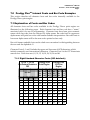
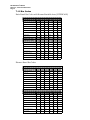
delay values and their corresponding times (in milliseconds).
PA/4000 User’s Manual
Section 5, Configuration
Page 16
DELAY
0
5
10
TIME
(MILLISECONDS)
72.2
90.4
111.5
25
50
75
100
150
200
250
170.9
277.9
376.9
479.2
681.7
884.4
1095.7
300
350
400
450
500
550
600
650
700
750
800
850
900
1300
1497.8
1708.7
1911
2116.3
2321.3
2523.8
2736.8
2939.3
3140.1
3344.9
3548.0
3758.4
950
999
3962.5
4160.4
PA/4000 User’s Manual
Section 5, Configuration
Page 17
To set the Product Delay value:
1. Start the conveyor.
2. Take the PA/4000 out of pause mode by pressing the PAUSE/RESUME
key on the Hand-Held terminal.
3. From the Menu screen, press the down arrow key three times.
4. The display shows the Product Delay screen.
5. Press the MENU/SELECT key to enter Edit mode (the value will flash).
6. Use the arrow keys to increase or decrease the Product Delay value.
7. Press the MENU/SELECT key to accept the changes. The value entered
will not be used until the MENU/SELECT key is pressed and the
display is no longer flashing.
8. Hold the 2nd key and press the MENU/SELECT key (while the display
is still flashing to CANCEL).
9. Repeat this process until the label is applied where you want it on the
product.
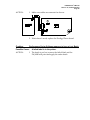
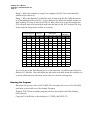
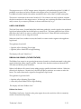
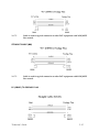
5.4.5 Setting the Position of the Label Present and Auto-Retract Sensors
The tamp pad assemblies for labels 4 inches long and greater will have more
than one location available for mounting the auto-retract sensor. The choice of
which location to use will depend on the direction of the product and whether
the label is being applied to the leading or trailing edge of the product. The
auto-retract sensor should be located in a position that will be towards the
inside of the product so that it can be assured of sensing the product regardless
of any changes in line speed. The bottom of the label present and auto-retract
sensors should initially be set to 0.20 inches from the bottom of the tamp pad. If
necessary the sensors can be moved up or down 0.05 inches to detect certain
labels or products.
POSITION OF LABEL PRESENT AND
AUTO RETRACT SENSORS
REAR PLATE
GASKET
IMPACT PLATE
.20” ± .05”
FOAM
PA/4000 User’s Manual
Section 5, Configuration
Page 18
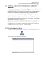
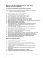
5.5 Example Job Setup
The following section shows an example job setup based on PA/4010.
NOTE: Move the PA/4000 away from the line until your Hand-Held
Terminal settings are correct.
STEP 1: After system installation and configuration, check for any errors. If the
system is operating normally, the screen will display ALL OK.
STEP 2: Go to the Menu screen.
Press the MENU/SELECT key or the down arrow key. This will take you
to the Menu screen.
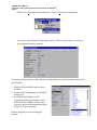
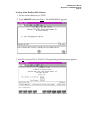
STEP 3: Clear the Item Count.
•
•
•
•
Press the MENU/SELECT key once to enter edit (flashing) mode.
Use the arrow keys to enter a Clear Count response of YES or NO.
TO ACCEPT CHANGES: Press the MENU/SELECT key.
TO CANCEL: While the display is still flashing, press and hold the 2nd
key followed by the MENU/SELECT key.
STEP 4: Set the Tamp Dwell value.
•
•
•
•
•
From the Clear Count screen, press the down arrow key once.
Press the MENU/SELECT key once to enter edit (flashing) mode.
For example, use the arrow keys to enter a Tamp Dwell value of 80.
TO ACCEPT CHANGES: Press the MENU/SELECT key.
TO CANCEL: While the display is still flashing, press and hold the 2nd
key followed by the MENU/SELECT key.
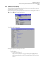
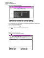
STEP 5: Set the Product Delay.
•
•
•
•
•
From the Tamp Dwell screen, press the down arrow key once.
Press the MENU/SELECT key once to enter edit (flashing) mode.
Use the arrow keys to enter a Product Delay In value of 100.
TO ACCEPT CHANGES: Press the MENU/SELECT key.
TO CANCEL: Press and hold the 2nd key followed by the
MENU/SELECT key.
STEP 6: Set the Output Delay .
•
•
•
•
•
From the Product Delay screen, press the down arrow key once.
Press the MENU/SELECT key once to enter edit (flashing) mode.
Use the arrow keys to enter an Output Delay value of 0.
TO ACCEPT CHANGES: Press the MENU/SELECT key.
TO CANCEL: Press and hold the 2nd key followed by the
MENU/SELECT key.
PA/4000 User’s Manual
Section 5, Configuration
Page 19
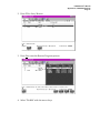
STEP 7: Set the Transfer.
•
•
•
•
•
From the Output Delay screen, press the down arrow key twice.
Press the MENU/SELECT key once to enter edit (flashing) mode.
Use the arrow keys to enter a Transfer value of OFF.
TO ACCEPT CHANGES: Press the MENU/SELECT key.
TO CANCEL: Press and hold the 2nd key followed by the
MENU/SELECT key.
STEP 8: Set the Sensor #1 Edge.
• From the Transfer screen, press the down arrow key once.
• Press the MENU/SELECT key once to enter edit (flashing) mode.
• Use the arrow keys to enter a Sensor #1 Edge value of L for leading edge
(we use leading edge because we want to place a label on the front edge
of the box.)
• TO ACCEPT CHANGES: Press the MENU/SELECT key.
• TO CANCEL: Press and hold the 2nd key followed by the
MENU/SELECT key.
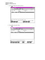
STEP 9: Set the Output Sensor.
•
•
•
•
•
From the Sensor #1 Edge screen, press the down arrow key twice.
Press the MENU/SELECT key once to enter edit (flashing) mode.
Use the arrow keys to enter an Output Sensor value of NC for no connect.
TO ACCEPT CHANGES: Press the MENU/SELECT key.
TO CANCEL: Press and hold the 2nd key followed by the
MENU/SELECT key.
STEP 10: Set the Darkness.
•
•
•
•
•
From the Output Sensor screen, press the down arrow key twice.
Press the MENU/SELECT key once to enter edit (flashing) mode.
Use the arrow keys to enter a Darkness value of 25.
TO ACCEPT CHANGES: Press the MENU/SELECT key.
TO CANCEL: Press and hold the 2nd key followed by the
MENU/SELECT key.
PA/4000 User’s Manual
Section 6, Operations
Page 1
6.0 OPERATIONS
6.1 Start of the Day
Step 1 – Check Configuration.
Look at the configuration sheet attached to the PA/4000 (see page 3 of this
section). Check all system settings against those recorded on the sheet.
Step 2 – Check Power.
1. Check that the OSHA air valve is in the CLOSED position.
2. Turn ON the power.
3. Check the air pressure.
4. Check the positions of all switches.
Step 3 – Check Consumables.
1. Check that there is a label roll loaded. Make sure that it is routed
correctly. See Section 4.13.
2. Check that there is a ribbon roll loaded. Make sure that it is intact
and routed correctly through the print engine. See Section 4.14.
Step 4 – Start Up.
1. If there are no problems or errors, the Hand-Held Terminal will
display “All OK”.
2. Press the PAUSE/RESUME key once. The display will read
“Printer Paused”.
3. Slide the air shut-off valve to the OPEN position.
Step 5 – Download Format.
1. At the PC send a batch of labels to the PA/4000.
2. Press the PAUSE/RESUME key once to enter print mode.
3. Note that the printer will expel two more labels after you expel
the first label. Remove these labels and send one more test
label to be sure that the PA/4000 is ready.
Step 6 – Turn on Conveyor.
PA/4000 User’s Manual
Section 6, Operations
Page 3
PA/4000
CONFIGURATION SHEET
Serial No.__________________________________________________________________
Production Line_____________________________________________________________
THESE VALUES SHOULD ONLY BE CHANGED BY MAINTENANCE OR OTHER TRAINED PERSONNEL
HAND HELD MENU SETTINGS
The values recorded on this sheet will be different from one production line to the next. Factors
such as line speed, distance from the PA4000 tamp pad to the product, and the location of the
product sensor will determine the actual values.
Menu
Clear Count*
NO
Tamp Dwell**_________
Product Delay**_______
Transfer
ON
OFF
Output Delay**________
Sensor #1 Edge
L
Output pulse**________
Sensor #2 Edge
L
Output Sensor
1
2
NC
T
Auto Retract
ON
T
Darkness________________
OFF
* Not a stored variable
**Line speed, tamp distance and other factors will determine actual value.
AIR CONTROL PSI SETTINGS
60
40
80
60
100
120
140
20
0
80
40
100
120
140
20
160
160
0
TAMP CYLINDER FLOW CONTROLS
See Section 5.4.1 for instructions on how to set air
flow controls. After air flow has been adjusted,
record here as a reference how many full turns
clockwise was made to attain the final settings.
Once set, do not change these settings.
_______________CW*
VACUUM
Draw in a line to
represent the needle
position and/or
write in the box an
approximate
numeric value.
AIR ASSIST
60
40
80
100
120
140
20
0
160
_______________CW*
REVISION 2.0 3/17/00
TAMP
*Number of turns clockwise relative to fully ccw position
PA/4000 User’s Manual
Section 6, Operations
Page 5
6.2 Adjustments during Operation
Print Quality PA/4000 Print engine has adjustments for controlling the quality
of print on the labels. Two of most important adjustments are
print darkness (printhead temperature) and print speed.
If you are using Performance Series for WindowsTM software, review
chapter 5 on Printing Formats in the Performance Series User’s
Manual to achieve the best contrast in print.
If your message contains bar codes, use a bar code verifier to
adjust for optimum print quality.
6.3 Stopping Label Application
Stop the unit by pressing the STOP/CLEAR key on the HandHeld Terminal.
6.4 End of the Day
Step 1 – Stop Label Application.
Press STOP/CLEAR key on the Hand-Held Terminal.
Step 2 – Stop the Conveyor.
Step 3 – Power OFF the PA/4000.
Step 4 – Slide the air shut-off valve to the CLOSED position.
Do not close the air shut-off valve before shutting off the
conveyor. The air cylinder/tamp pad assembly could fall and
damage a product.
Step 5 – Clear the Label off the Tamp Pad.
Step 6 – Clean the Sensors.
If available, use compressed air to clean the sensors. Wiping the
sensors to clean them is not nearly as effective as an air gun.
PA/4000 User’s Manual
Section 7, Fonts and Bar Codes
Page 1
7.0 Prodigy PlusTM Internal Fonts and Bar Code Examples
This section describes all character fonts and bar codes internally available in the
Prodigy PlusTM print engine.
7.1 Explanation of Fonts and Bar Codes
All character fonts and bar codes available in the Prodigy PlusTM print engine are
illustrated on the following pages. Each character font and bar code has a “name”
associated with it for use in programming. Character fonts have been given numeric
names while bar code fonts are selected by alpha names. Bar code fonts in uppercase
alpha names will print bar codes with human readable interpretations. Bar code fonts in
lowercase alpha names will be the same codes printed as bars only.
Bar code human readable fonts use the slash zero convention for distinguishing between
the zero and the alphabetic O.
Character Fonts 0, 1 and 2 include the upper and lowercase ASCII characters, which
include commonly used international characters. Character Font 9 is the CG Triumvirate
smooth font. Point sizes are 6, 8, 10, 12, 14, 18, 24, 30, 36 and 48.
7.1.1 Eight Standard Character Fonts (203 dots/inch)
CPI at 1, 2 & 3X
Dot Pattern Rotations
DPI
Dot Size
Dot W Dot Sp
Prodigy Plus
Print Engine
Prodigy Plus
152 Print
Engine
1x1
All
Rot
200
2x2
All
Rot
100
2x3
1x1
All
All
Rot 2 Rot
& 4 153.8
2x2
All
Rot
76.3
2x3
Rot 2
&4
51.3
0.005
0.010
0.015
0.0065 0.0130 0.0195
Font
Dot H
0
7
5
1
33.83
16.92
11.28
25.64
12.82
8.55
1
13
7
2
22.56
11.28
7.52
17.09
8.55
5.70
2
18
10
2
16.92
8.46
5.64
12.82
6.41
4.27
3
27
14
2
12.69
6.34
4.23
9.62
4.81
3.21
4
36
18
3
9.67
4.83
3.22
7.33
3.66
2.44
5
52
18
3
9.67
4.83
3.22
7.33
3.66
2.44
6
64
32
4
5.64
2.82
1.88
4.27
2.14
1.42
7
32
15
5
10.15
5.08
3.38
7.69
3.85
2.56
8
28
15
5
10.15
5.08
3.38
7.69
3.85
2.56
PA/4000 User’s Manual
Section 7, Fonts and Bar Codes
Page 2
7.1.2 Bar Codes
Ratio Based Bar Codes with Human Readable fonts (UPPERCASE)
Prodigy Plus (actualD P I-203)
Ratio
2:1
5:2
3:1
2:1
5:2
3:1
N arrow BarN am e
0.005
0.005
0.005
0.010
0.010
0.010
A 3O F9
15.62
7
12.69
7.81
3.5
6.34
D I2O F5
14.5
6.34
11.28
7.25
3.17
6.64
H H IBC
15.62
7
12.69
7.81
3.5
6.34
I CO D A BA R
14.5
6.34
11.28
7.25
3.17
5.64
J I2O F5 W /BA RS
16.92
7.25
12.69
8.46
3.63
6.34
K PLESSEY
20.3
9.23
16.92
10.15
4.61
8.46
L U PC CA SE
14.5
6.34
11.28
7.25
3.17
5.64
Prodigy Plus 152
(actualDPI- 153.8)
2:1
5:2
3:1
2:1
5:2
3:1
N arrow BarN am e
0.006
0.006
0.006
0.0130 0.0130 0.0130
A 3O F9
11.83
5.31
9.62
5.92
2.65
4.81
D I2O F5
10.99
4.81
8.55
5.49
2.40
4.27
H H IBC
11.83
5.31
9.62
5.92
2.65
4.81
I CO D A BA R
10.99
4.81
8.55
5.49
2.40
4.27
J I2O F5 W /BA RS
12.82
5.49
9.62
6.41
2.75
4.81
K PLESSEY
15.38
6.99
12.82
7.69
3.50
6.41
L U PC CA SE
10.99
4.81
8.55
5.49
2.40
4.27
4
6
8
Element Based Bar Codes
Prodigy Plus (actualD PI-203)
M ultiplier=
1
N arrow BarW idth
0.0049 0.0049 0.0049 0.0049 0.0049 0.0049
2
3
B U PC-A
38%
76%
114%
152%
227%
303%
C U PC-E
38%
76%
114%
152%
227%
303%
E CO D E128 (B)
9.23
3.69
6.15
4.61
1.85
3.08
F EA N -13
38%
76%
114%
152%
227%
303%
G EA N -8
38%
76%
114%
152%
227%
303%
M U PC 2D IG A D D
38%
76%
114%
152%
227%
303%
N U PC 5D IG A D D
38%
76%
114%
152%
227%
3.03
O CO D E93
11.28
4.51
7.52
5.64
2.26
3.76
3
4
6
8
Prodigy Plus 152 (actualDPI- 153.8)
M ultiplier=
1
2
N arrow BarW idth
0.0065 0.0065 0.0065 0.0065 0.0065 0.0065
B U PC-A
50%
100%
150%
200%
300%
400%
C U PC-E
50%
100%
150%
200%
300%
400%
E CO D E128 (B)
6.99
2.8
4.66
3.5
1.40
2.33
F EA N -13
50%
100%
150%
200%
300%
400%
G EA N -8
50%
100%
150%
200%
300%
400%
M U PC 2D IG A D D
50%
100%
150%
200%
300%
400%
N U PC 5D IG A D D
50%
100%
150%
200%
300%
400%
O CO D E93
8.55
3.42
5.70
4.27
1.71
2.85
PA/4000 User’s Manual
Section 7, Fonts and Bar Codes
Page 3
7.2 Internal Font Examples
These font examples are of all nine Prodigy PlusTM standard internal fonts. They are
numerically named. All examples are printed with a 10 x 10 mil pixel size, and a 1x
magnification on the horizontal and vertical dot patterns.
Font 0
Identifies a 96-character alphanumeric font. Uppercase and lowercase.
Characters are 7 dots high, 5 dots wide, and 1 dot spacing.
Prodigy Plus
Prodigy Plus 152
Font 1
Identifies a 145-character uppercase and lowercase alphanumeric font that
includes descenders and ascenders. Characters are 9 dots high, 9 dots wide, and
2 dots spacing (International characters are 13 dots high, 7 dots wide, and 2 dots
spacing).
Prodigy Plus
Prodigy Plus 152
PA/4000 User’s Manual
Section 7, Fonts and Bar Codes
Page 4
Font 2
Identifies a 138-character alphanumeric upper and lowercase font. Characters
are 18 dots high, 10 dots wide, and 2 dots spacing.
Prodigy Plus
Prodigy Plus 152
Font 3
Identifies a 62-character alphanumeric font, uppercase. Characters are 27 dots
high, 14 dots wide, and 2 dots spacing.
Prodigy Plus
Prodigy Plus 152
PA/4000 User’s Manual
Section 7, Fonts and Bar Codes
Page 5
Font 4
Identifies a 62-character alphanumeric font, uppercase. Characters are 36 dots
high, 18 dots wide, and 3 dots spacing.
Prodigy Plus
Prodigy Plus 152
PA/4000 User’s Manual
Section 7, Fonts and Bar Codes
Page 6
Font 5
Identifies a 62-character alphanumeric font, uppercase. Characters are 52 dots
high, 18 dots wide, and 3 dots spacing.
Prodigy Plus
Prodigy Plus 152
PA/4000 User’s Manual
Section 7, Fonts and Bar Codes
Page 7
Font 6
Identifies a 62-character alphanumeric font, uppercase. Characters are 64 dots
high, 32 dots wide, and 4 dots spacing.
Prodigy Plus
PA/4000 User’s Manual
Section 7, Fonts and Bar Codes
Page 8
Prodigy Plus 152
PA/4000 User’s Manual
Section 7, Fonts and Bar Codes
Page 9
Font 7
Identifies a font that prints OCR-A, size I. Characters are 32 dots high, 15 dots
wide, and 5 dots spacing.
Prodigy Plus
Prodigy Plus 152
Font 8
Identifies a font that prints OCR-B, size III. Characters are 28 dots high, 15 dots
wide, and 5 dots spacing.
Prodigy Plus
Prodigy Plus 152
PA/4000 User’s Manual
Section 7, Fonts and Bar Codes
Page 10
Font 9
Identifies the CG Triumvirate smooth font. The characters are available in upper
and lowercase. Point sizes are selected by number in the bar code height.
Prodigy Plus
PA/4000 User’s Manual
Section 7, Fonts and Bar Codes
Page 11
(Font 9 Continued)
Prodigy Plus 152
PA/4000 User’s Manual
Section 7, Fonts and Bar Codes
Page 12
7.3 Bar Code Examples
Bar Code A
Identifies the Code 3 of 9 bar code with a human readable font. Code 39 is an
uppercase, alphanumeric bar code that is variable in length. The valid ASCII characters
for this font are: 32, 36-37, 42-43, 45-47, 48-57, 65-90. Code 3 of 9’s normal wide to
narrow bar ratio is 3:1.
Prodigy Plus
Prodigy Plus 152
Bar Code B
Identifies the UPC-A bar code. Numeric-only bar code with a fixed length of 12
characters. Eleven digits supplied by host or application software, 12th digit checksum
supplied by printer. If the 12th digit is sent by the host, the printer will check that
character against the calculated checksum and will print the bar code as all zeros if they
do not match. Addendum codes for this font are described by fonts M and N. The
normal ratios that the printer can print are 1:1, 2:2, 3:3, 4:4, 6:6, and 8:8. These ratios
actually specify size of elements since UPC type bar codes are element based and not
ratio based. (Maximum 10 bar codes per label.)
Prodigy Plus
Prodigy Plus 152
PA/4000 User’s Manual
Section 7, Fonts and Bar Codes
Page 13
Option V- Identifies Random Weight UPC bar code. The seventh digit supplied by the
host or application software must be an uppercase V followed by 4 digit weight
information. Eleven digit checksum is supplied by the printer.
Prodigy Plus
Prodigy Plus 152
Bar Code C
Identifies the truncated UPC-E bar code. Numeric-only bar code with a fixed length of 7
characters. Six digits supplied by host or application program, 7th digit checksum
supplied by printer. If the 7th digit is sent by the host, the printer will check that character
against the calculated checksum and will print the bar code as all zero if they do not
match. Addendum codes for this font are described by fonts M and N. The normal ratios
that the printer can print are 1:1, 2:2, 3:3, 4:4, 6:6, and 8:8. These ratios actually specify size
of elements since UPC type bar codes are element based and not ratio based.
Prodigy Plus
Prodigy Plus 152
Bar Code D
Identifies the Interleaved 2 of 5 bar code. I 2 of 5 is a numeric-only code. The ASCII
range for the numeric codes is 48-57. Code I 2 of 5’s normal wide to narrow bar ratio is
5:2. (Maximum 8 bar codes per label.)
Prodigy Plus
Prodigy Plus 152
PA/4000 User’s Manual
Section 7, Fonts and Bar Codes
Page 14
Bar Code E
Identifies the Code 128 variable length bar code with modulo 103 checksum calculation.
Code 128 can encode the entire 128 ASCII character set, including both uppercase and
lowercase alpha characters. Code 128 is an element based bar code similar to the UPC
fonts. Therefore ratios must be equal to one. The valid ratios are 1:1, 2:2, 3:3, 4:4, 6:6
and 8:8.
The Prodigy PlusTM supports Code 128 Code Subset A, B, and C. You can select the
printer to start on any code subset and switch to another with the data area (default is
subset B).
Code Subset A includes all of the standard upper case alphanumeric keyboard
characters plus the control and the special characters. To select Code Subset A, precede
the data to be encoded with an ASCII A (DEC 65, HEX 41).
Code Subset B includes all of the standard upper case alphanumeric keyboard
characters plus lower case alphabetic and special characters. To select Code Subset B,
precede the data to be encoded with an ASCII B (DEC 66, HEX 42). If no start character
is sent for the 128 font, Code Subset B will be selected by default.
Code Subset C includes the set of 100 digit pairs from 00 through 99 inclusive, as well as
special characters. Code Subset C is used for double density encoding of numeric data.
To select Code Subset C, precede the data to be encoded with an ASCII C (DEC 67, HEX
43). You must not try to encode alpha data if you select Code Subset C.
Special Character Handling
Characters above ASCII value 95 are considered special characters. To access these
values, a two character reference table has been built into the Prodigy PlusTM Label
Printer. The following table describes this reference.
ASCII
2 CHAR
CODEA
CODEB
CODEC
96
&A
FNC3
FNC3
-NA-
97
&B
FNC2
FNC2
-NA-
98
&C
SHIFT
SHIFT
-NA-
99
&D
CODEC
CODEC
-NA-
100
&E
CODEB
FNC4
CODEB
101
&F
FNC4
CODEA
CODEA
102
&G
FNC1
FNC1
FNC1
PA/4000 User’s Manual
Section 7, Fonts and Bar Codes
Page 15
As an example, to get FNC2 to be encoded into a Code Subset A bar code, send the
ASCII & (ASCII 38, HEX 26) followed by an ASCII B (DEC 66, HEX 41), code FNC2
will be encoded.
Example:
ATEST&B123
Data Encoded:
TEST<FNC2>123
Control Codes
Control characters can be encoded into Code Subset A by sending the lowercase
ASCII characters a-z, a = SOH, b = STX, c = ETX and so on.
Font Sizing
The font sizing for a 128 on Rotation #2 is not consistent because of the variable
character code to character correlation. Therefore the row address may have to be
adjusted to place it properly.
Prodigy Plus
Prodigy Plus 152
PA/4000 User’s Manual
Section 7, Fonts and Bar Codes
Page 16
Bar Code F
Identifies the standard EAN-13 bar code, Numeric-only bar code; fixed in length.
Twelve digits are supplied by host or application software, 13th digit checksum
supplied by printer. If the 13th digit is sent by the host, the printer will check that
character against the calculated checksum and will print the bar code as all zeros if they
do not match. Addendum codes for this font are described by fonts M and N. The
normal ratios that the printer can print are 1:1, 2:2, 3:3, 4:4, 6:6 and 8:8. These ratios
actually specify size of elements since EAN type bar codes are element based and not
ratio based. Maximum 12 bar codes per label.
Prodigy Plus
Prodigy Plus 152
Bar Code G
Identifies the truncated EAN-8 bar code. Numeric-only bar code; fixed in length.
Seven digits are supplied by host or application software, 8th digit supplied by printer.
If the 8th digit is sent by the host, the printer will check that character against the
calculated checksum and will print the bar code as all zeros if they do not match.
Addendum codes for this font are described by fonts M and N. The normal ratios that
the printer can print are 1:1, 2:2, 3:3, 4:4, 6:6 and 8:8. These ratios actually specify size of
elements since EAN type bar codes are element based and not ratio based.
Prodigy Plus
Prodigy Plus 152
PA/4000 User’s Manual
Section 7, Fonts and Bar Codes
Page 17
Bar Code H
Identifies the HIBC (modulo 43 checksum) version of the code 3 of 9 bar code. The
checksum will be placed at the end of the data string that is received from the host. The
host device must supply a leading + to identify the data format type. Code 39 is an
uppercase, alphanumeric bar code that is variable in length. The valid ASCII characters
for this font are 32, 36-39, 42-43, 45-47, 48-57 and 65-90. Code 3 of 9’s normal wide to
narrow bar ratio is 3:1.
Prodigy Plus
Prodigy Plus 152
Bar Code I
Identifies the 20-character CODABAR bar code. CODABAR is basically a numeric bar
code with some special additional characters. These characters are 0123456789ABCD$+-./.
The length of the code is variable and is normally printed with a 3:1 ratio. CODABAR
needs a start and stop character.
Prodigy Plus
Prodigy Plus 152
PA/4000 User’s Manual
Section 7, Fonts and Bar Codes
Page 18
Bar Code J
Identifies an I 2 of 5 bar code with modulo 10 checksum calculation. The ASCII range
for the numeric codes is 48-57. Code I 2 of 5’s normal wide to narrow bar ratio is 5:2.
Font D and L also print different forms of the I 2 of 5 bar code. Maximum 8 bar codes
per label.
Prodigy Plus
Prodigy Plus 152
Bar code K
Identifies the Plessey bar code.
Prodigy Plus
Prodigy Plus 152
PA/4000 User’s Manual
Section 7, Fonts and Bar Codes
Page 19
Bar Code L
Identifies an I 2 of 5 bar code with modulo 10 checksum (UPC shipping container
symbology) that does the special human readable formatting for and adds bearer bars
to the top and bottom of bars when encoding 13 digits. The ASCII range for the
numeric codes is 48-57. Code I 2 of 5’s normal wide to narrow bar ratio of 5:2. Font d
and L also print different forms of the I 2 of 5 bar code. There must be a maximum of 8
bar codes per label.
Prodigy Plus
Prodigy Plus 152
Bar Code M
Identifies the 2 digit addendum code for UPC fonts. It is a numeric-only bar code with
a fixed length of 3 characters. Two characters supplied by the host or application
software, the third digit checksum supplied by printer. If the third digit is sent by the
host, the printer will check that character against the calculated checksum and will print
the bar code as all zero if they do not match. Addendum
codes for this font are described by fonts M and N. The normal ratios that the printer
can print are 1:1, 2:2, 3:3, 4:4, 6:6 and 8:8. These ratios actually specify size of elements
since UPC type bar codes are element based and not ratio based. It must be placed after
the UPC/EAN code manually. This code should be placed 9 moduli away from the end
of preceding bar codes.
Prodigy Plus
Prodigy Plus 152
PA/4000 User’s Manual
Section 7, Fonts and Bar Codes
Page 20
Bar Code N
Identifies the 5 digit addendum code for UPC fonts. It is a numeric-only bar code with
a fixed length of 6 characters. Two characters supplied by the host or application
software, the sixth digit checksum supplied by printer. If the sixth digit is sent by the
host, the printer will check that character against the calculated checksum and will print
the bar code as all zeros if they do not match. Addendum codes for this font are
described by fonts M and N. The normal ratios that the printer can print are 1:1, 2:2, 3:3,
4:4, 6:6 and 8:8. These ratios actually specify size of elements since UPC type bar codes
are element-based and not ratio based. It must be placed after the UPC/EAN code
manually. This code should be placed 9 moduli away from the end of preceding bar
codes.
Prodigy Plus
Prodigy Plus 152
Bar Code O
Identifies the Code 93 bar code. Code 93 is an upper and lower case alpha numeric bar
code. The normal ratios that the printer can print are 1:1, 2:2, 3:3, 4:4, 6:6 and 8:8. These
numbers actually specify size of magnification and are element-based, not ratio based.
The ASCII characters that are permissible for Code 93 are :
,�$%*+
ABCDEFGHIJKLMNOPQRSTUVWXYZ0123456789
abcdefghijklmnopqrstuvwxyz.
Prodigy Plus
Prodigy Plus 152
PA/4000 User’s Manual
Section 7, Fonts and Bar Codes
Page 21
Bar Code P
Postnet bar code. This is the small bar code on letters encodes Zip codes. It usually
contains a 9 digit code followed with a checksum value. Sometimes a two digit post
office code will be attached to the zip code.
Bar Code Q
UCC/EAN 128 bar code. This code must have 19 digits sent to the printer for the code
to print out.
Bar Code R
UCC/EAN 128 bar code. This bar code is set up for the K-MART specifications. This
code must have 18 digits sent to the printer for the code to print out.
PA/4000 User’s Manual
Section 7, Fonts and Bar Codes
Page 22
7.4 Sample Label Parameters and Fonts
The sample label parameters and fonts illustrated apply to the standard Prodigy Plus 203 dpi.
^BL
D11
191100900000055CM2160-CAM
1a6204000800015CM2160-CAM
112200000650065CM2160-CAM
191100502600020BMM CAMCORDER
191100502350020WITH REMOTE
191100302050020* Autofocus
191100301850020* High-Fidelity Sound
191100301570020* 8:1 Speed Zoom
191100301380020* 2 Lux Light Sensitivity
1X1100001300010B200160002002
1X1100001800012L196002
1X1100002300012L196002
1Y1100001270250CAM
1Y1100002950013LOGO
E
NOTE: Field with font type Y specifies an image loaded in a memory module.
PA/4000 User’s Manual
Section 7, Fonts and Bar Codes
Page 23
^BL
D22
1911002014500552345
1E2212500000005C005940928123401&E^
1X1100001450010B300060002002
1X1100001750012L296002
1X1100001470115L002028
1X1100001470235L002028
1X1100001770235L002026
1X1100001770185L002026
101100001500015NUMBER
101100001600015SERIAL
101100001500118PRODUCT
101100001500240BRAND
101100001800240LINE
101100001800015PLANT
191100301740070P-12621
191100301740190KK
19110030174027501
191100201450159005940
191100201450268928
4a3104000000380ABCDE12345
121100103000000PRODIGY PLUS WITH RIBBON SAVER
E
PA/4000 User’s Manual
Section 7, Fonts and Bar Codes
Page 24
^BL
D11
491100600850333000001
+01
4a9305000100380S000001
+01
421100000100328 (S)
4211000001003128SERIAL
1X1100004130305L002090
1X1100005030305L002090
4a9305000100300V032380
421100000100248 (V)
421100000100238SUPPLIER
491100600850252032380
1X1100000100225L002590
4a9305000100220Q30
421100000100135 (Q)
421100000100125QUANTITY
49110090085016830
1X1100000100113L002590
4a9305000100108P72715-FE3-0030
421100000100030 (P)
421100000100020PART NO.
49110090085006272715-FE3-0030
491100200100393
1X1100002900115L110003
1X1100004100227L175003
1X1100005100227L175003
491100804220380AA
421100004220320ZONE
491100805220380CC
421100005220320PLANT
43130000430029003-13-70
421100004220240MFG. DATE
421100005220240AUDITOR
491100805220295RW
491100803020215PANEL
491100803020170LF DOOR
421100003020125DESCRIPTION
E
PA/4000 User’s Manual
Section 7, Fonts and Bar Codes
Page 25
^BL
D11
4a620500020008533121111111
49110060020003533121111111
431100002300025(1P)
4a6205000200174AA10000
491100600200123AA10000
431100001700115(S)
4911005001002103300 12X12 CORDED TABLET WITH
491100500100230BUTTON INLINE CURSEOR - PC
491100500100250100/110
1X1100000040180L004392
1X1100000040270L004392
491100400100295DIAGRAPH CORPORATION
4911004001003123401 RIDER TRAIL SOUTH
491100400100347 USA
491100400100363 (800) 521-3047
4a620500270036097598
49110060270030597598
431100003500300 (2V)
1X1100002500274L092004
491100400100330 EARTH CITY, MO 63045
E
PA/4000 User’s Manual
TM
Section 8, Printing Labels with Performance Series for Windows
Page 1
8.0 PRINTING LABELS WITH PERFORMANCE SERIES FOR
WINDOWSTM
For optimum performance, ease and convenience, Diagraph recommends the labeling
software package called Performance Series for WindowsTM .
Diagraph’s Performance Series for WindowsTM creates labels and combines a database
for storage with capabilities for serialized fields. It has on screen graphics that
accurately represent the format while it is being built field by field. It supports
many windows features. With the Window Recorder Function you can record a
sequence of keystrokes and mouse actions called a macro. Using a macro can
shorten any frequently used phrase or steps of any routine. This software supports
the fonts and barcodes resident in the Prodigy PlusTM print engine. It also supports
the graphic file types, .BMP, .PCC and .PCX.
This section describes printer configuration and label formatting specifically for the
PA/4000. This section does not contain information about creating, editing or
deleting labels from your database. For information on these topics, consult your
Diagraph Performance Series for WindowsTM Software Manual.
8.1 Printer Configuration Setup
From the Windows Program Manager, double-click on the Performance Series icon.
The Performance Series Main Menu will appear:
PA/4000 User’s Manual
TM
Section 8, Printing Labels with Performance Series for Windows
Page 2
Click on the Settings from the Menu bar. Click on Printer Configuration.
You will see the Printer Configuration menu. Click on the printer you will use.
A configuration menu appears:
You must set three options under Printer Configuration to use Performance Series with
the PA/4000.
1. Click on Printer Model and set the to
PA4000.
2. Set the Offset Adjustment to 0 (Default
setting is 0).
3. Set Translucent Ribbon to NO
regardless of the type of ribbon used.
The Hand-Held Terminal allows the
system to print with translucent ribbon
using the Transfer function.
Restart program to activate changed
options.
PA/4000 User’s Manual
TM
Section 8, Printing Labels with Performance Series for Windows
Page 3
8.2 Label Format Setup
After the Printer Configuration options have been set, you are ready to open an
existing label and format it. To do this:
Click on the Open icon from the Menu bar and choose an existing label. Click on
View then on Change Format Specification.
You will see the Format screen.
Change the options by clicking on the item.
Set the options:
1. Set the Label Offset to 0.
(May need to be adjusted. If you are driving the PA4000 directly
with custom software, set the DIP switch positions DSW1 as shown
below).
PA/4000 User’s Manual
TM
Section 8, Printing Labels with Performance Series for Windows
Page 4
2. Set the Presentation Position to 0.
(May need to be adjusted. If you are driving the PA4000 directly
with custom software, set the DIP switch positions DSW1 as shown
below).
SW1-1
SW1-2
SW1-3
SW1-4
SW1-5
SW1-6
SW1-7
SW1-8
Depends on RS-232 Baud Rate
Depends on RS-232 Baud Rate
Depends on RS-232 Baud Rate
depends on number of databits
OFF PA4000
ON Enable label present sensor*
OFF Standard ribbon
ON Enable cutter*
*Required
3. Set the Cut Option to 1
4. For label offset of 95 must transmit 0198.
5. For presentation position of 155 must transmit f283.
Refer to Datamax Prodigy PlusTM Print Engine programming
guide for more information. The guide can be downloaded free
from www.datamaxcorp.com.
Please note that the offset and presentation position may need to
be adjusted to get label properly dispensed and print position set
correctly.
Click OK to set the new format.
The Performance Series for WindowsTM Software allows you to control two different
label offsets.
1. All LABEL OFFSET ADJUSTMENT - controls the offset value for
all of the labels in your database. This is found under the Settings Printer Configuration menu. Click twice on the printer chosen and
this screen appears:
PA/4000 User’s Manual
TM
Section 8, Printing Labels with Performance Series for Windows
Page 5
2. SPECIFIC LABEL OFFSET - controls the offset value for a specific
label in your database. This is found under the View – Change
Format Specification menu when you have an existing label opened.
IMPORTANT: The total offset value of the label is determined by
adding the OFFSET ADJUSTMENT and LABEL OFFSET values
together.
PA/4000 User’s Manual
TM
Section 8, Printing Labels with Performance Series for Windows
Page 6
8.3 Printing a Label
Double-click on the Performance Series icon.
The Performance Series Main Menu will appear.
Click on the Printer icon.
The Print Format screen will appear. Click on a label to be printed and click Open.
When the label opens click the printer icon to send that label to the printer.
PA/4000 User’s Manual
TM
Section 8, Printing Labels with Performance Series for Windows
Page 7
Once you have sent a label to print, the Print Request screen will appear.
Click OK to download the selected label to the PA/4000.
PA/4000 User’s Manual
Section 9, Maintenance
Page 1
9.0 MAINTENANCE
9.1 Daily Maintenance
Clean the Printhead.
! Turn OFF the printer and unplug the unit from the outlet before
cleaning the printhead. Clean the printhead after each
ribbon/label change. Clean with alcohol and swabs.
Clean the Air Filter.
! Purge by cycling the OSHA valve ON and OFF.
! Check air pressure setting.
9.2 Weekly Maintenance
Clean the Label Low Sensor located behind the Label Supply Disc.
! Blow off with dry shop air to remove dust and adhesive.
Clean the Label Present Sensor on the Tamp Pad.
! Blow off with dry shop air to remove dust and adhesive.
Clean the Auto-Retract Sensor on the Tamp Pad.
! Blow off with dry shop air to remove dust and adhesive.
9.3 Monthly Maintenance
Clean the Label Low Sensor located behind the Label Supply Disc.
! Clean with an alcohol swab.
Clean the Leading Edge Sensor on the Print Engine.
! Clean with an alcohol swab.
Clean the Ribbon Sensor on the Print Engine.
! Clean with an alcohol swab.
Clean the Label Rollers and Guides of Label Residue.
! Clean with an alcohol swab.
Clean the Ribbon Rollers and Guides of Ribbon Residue.
! Clean with an alcohol swab.
PA/4000 User’s Manual
Section 9, Maintenance
Page 2
9.4 Six Month Maintenance
Replace the Vacuum Filter.
! This filter—6150322—is available in the PA/4000 Filter Kit, 6150-806.
9.5 Intermittent Maintenance
! Clean the printhead each time the label and/or ribbon is replaced.
! Replace the printhead when any degradation in print quality is noticed.
!
CAUTION: Utilize the appropriate safety equipment as prescribed by your
supervisor during the performance of routine periodic maintenance.
!
WARNING: Loss of air pressure can cause the tamp head assembly to
drop into the path of the oncoming product. This can damage the
PA/4000. To prevent this, be sure there are no products on the line or
pull the PA/4000 away from the line before sliding the air valve to OFF.
9.6 Yearly
Inspect the print engine drive roller for debris, cuts or other wear or damage.
PA/4000 User’s Manual
Section 10, Troubleshooting
Page 1
10.0 TROUBLESHOOTING
Attention to detail and common sense will greatly reduce the risk of
accidents. For safety, always stop the conveyor first.
Whenever troubleshooting, always start by checking for error messages
on the Hand-Held Terminal.
Cautions
•
Triple check the photosensor distance.
•
Disable the secondary wipe-down when not in use. Change the output
pulse value to 25 with the Hand-Held terminal, the cylinder will not
fire if the output pulse value is 25 or lower.
•
Make sure the edge value for the photosensor 1 is correct.
•
Check that the tamp dwell setting is correct.
10.1 POWER PROBLEMS
Problem:
The power LED light is not lit.
Possible Cause:
Loss of power.
ACTION:
1. Make sure that the power cord is undamaged and plugged into
a 120V outlet.
2. Make sure that the power switch is turned ON.
3. Check the fuses.
4. Check for bad electrical outlet.
Problem:
On start up, the solenoids continue cycling, there is no
digital on the hand-held and all lights are on or flashing.
Possible Cause:
ACTION:
Problem:
Applicator board is bad.
Replace the applicator board.
No motor voltage, engine will not run.
Probable Cause: Prodigy PlusTM board is bad.
ACTION:
Check the printhead cable. Check motor for continuity. Check the
input voltage to the Prodigy PlusTM board from the transformer
and diode block. If all is well, replace the Prodigy PlusTM board.
PA/4000 User’s Manual
Section 10, Troubleshooting
Page 2
Problem:
No motor response and printer error shows on hand-held
after 2 seconds following pushing of the feed button.
Probable Cause:
Prodigy Plus board or motor is bad.
ACTION:
Check the voltage to the Prodigy PlusTM board. Check that the
cables are properly plugged in. Check the solder joints on the
stepper motor. If solder is bad replace the motor. If there is still
no response, replace the Prodigy PlusTM board.
Problem:
No voltage from Prodigy PlusTM board to Applicator board.
Probable Cause:
ACTION:
Applicator board is bad.
Check the motor voltage at TP4.
10.3 PRINTING PROBLEMS
Problem:
ACTION:
No power.
Power Problems, see Section 10.2.
Problem:
Won’t print
Possible Cause:
ACTION:
Press PAUSE/RESUME key to resume printing.
Possible Cause:
ACTION:
Ribbon or labels not routed correctly.
Re-route ribbon or label. See Sections 4.13 and 4.14.
Possible Cause:
ACTION:
Printhead lift lever is not locked down.
Push lever down.
Possible Cause:
ACTION:
Bad cable connection.
Check cable connection.
Possible Cause:
ACTION:
Label present sensor saturated.
Shade the PA/4000 from all ambient light.
Possible Cause:
ACTION:
PC has not sent a batch of labels to the PA/4000.
Send the labels.
Possible Cause:
ACTION:
Printer could be stopped.
Press PAUSE/RESUME key to resume printing.
Possible Cause:
ACTION:
Printer could be in pause mode.
The label-present sensor is dirty or blocked.
Clean the sensor with a soft-tipped swab and isopropyl alcohol.
PA/4000 User’s Manual
Section 10, Troubleshooting
Page 3
Possible Cause:
Ribbon or label roll may be bad.
ACTION:
Change ribbon or label roll.
Problem:
Printer skips every other label
Possible Cause:
Line is moving too fast for selected print speed.
ACTION:
Select new print speed with your labeling software package.
Problem:
Printer continues to run after ribbon has run out.
Possible Cause:
ACTION:
Problem:
Set transfer to ON via the hand-held terminal.
The print engine is feeding out blank labels.
Blank labels can be the result of a label problem, a ribbon problem or a
software problem.
Possible Cause:
ACTION:
Blank label format downloaded.
Check the Performance SeriesTM or other software manual for label
formatting procedures.
Possible Cause:
ACTION:
Low darkness setting
1. Check the Performance SeriesTM or other label-formatting
software manual for appropriate label darkness settings.
2. Check the Hand-Held terminal darkness setting. See
Section.5.2.
Possible Cause:
ACTION:
Failed true type font and/or graphic download.
Check both the manual for your label-formatting software and the
print engine manual. Verify parameters, reset and try again.
Possible Cause:
ACTION:
Wrong ribbon is loaded
Different print engines have different ribbon requirements. Make sure
that the ribbon loaded in your print engine is compatible. Check the
print engine manual or call Diagraph at 1-800-526-2531.
Possible Cause:
ACTION:
The ribbon is loaded incorrectly.
Compare the path of the ribbon with the path shown on the label
inside the print engine housing.
Possible Cause:
ACTION:
Transfer menu select item in the hand-held terminal is
set to OFF.
The ribbon and the label are incompatible
Unsatisfactory printing occurs when the print engine has been set for
direct-thermal printing but has been loaded with labels that require a
PA/4000 User’s Manual
Section 10, Troubleshooting
Page 4
ribbon for good print contrast. To avoid this situation, make sure that
you use labels designed for direct-thermal printing. If your print
engine has been set to print with a ribbon in the thermal transfer mode,
use ATS labels—Diagraph labels designed for thermal transfer
printing.
Possible Cause:
ACTION:
Refer to the Performance SeriesTM or other label-format software
manual for correct configuration.
Possible Cause:
ACTION:
The ribbon is broken.
Check for error messages on the Hand-Held terminal LCD. Replace
broken ribbon and check ribbon tension.
Possible Cause:
ACTION:
Right-hand vs. left-hand print engine driver configuration.
The ribbon has been loaded upside down.
When the ribbon is loaded upside down, the ink adheres to the
printhead and not to the label. Remove the ribbon and install it
correctly. Clean the printhead with isopropyl alchohol.
Software Causes: The message is blank, has incorrect parameters (such
as Offset) or is requesting something the printer does
not understand such as a special font or graphic.
ACTION:
Problem:
Examine the message and all its requirements. If all print demands
seem to fall within the capabilities of the print engine, run a test
label. If the label still prints blank, exit the software and reenter. Try
printing the label again. Often, a warm reboot will produce a
successful printing.
The labels are only partially printed.
Probable Cause:
ACTION:
Problem:
Pause the PA/4000. Release the printhead lift lever. Remove label
stock from printer. Clean debris from the label drive roller. Roller
can be turned by hand. Reload label stock and lower printhead lift
lever to lock the printhead in place.
Gaps in line of print.
Probable Cause:
ACTION:
Accumulated material on the label drive roller located
behind the peel blade.
Label drive roller needs replacing on the engine assembly.
Replace label drive roller.
PA/4000 User’s Manual
Section 10, Troubleshooting
Page 5
Problem:
ACTION:
No cutter signal.
Check cutter cable connections and conditions. May need to
replace Prodigy PlusTM Board.
Problem:
No solenoid reset (clicking) on turning switch ON.
Probable Cause:
Transformer is bad or there is a bad cable.
ACTION:
Check the input voltage from voltage regulator to applicator
board. It should read 0, 5, 25, 0 (white, green, red, black). If the
green lead is below 5V, check the voltage across the blue to blue
and red to red on the Prodigy J5 plug. It should read 8.5+ volts
on each side. If it doesn’t read that, the transformer is bad.
Unplug all the prodigy cables except J5, J9, J6 and J7 from the
rectifier block. Replug one at a time while checking the 5 volt
lead on J3. A bad cable will cause a voltage drop, replace the
cable.
Problem:
Ribbon and Label won’t back up after each label prints.
Probable Cause:
Label drive roller gear set screw is stripped.
ACTION:
Replace set screw.
Problem:
Edge sensor voltage of 5V will not adjust.
Probable Cause:
Edge sensor or applicator board is bad.
ACTION:
Pull edge sensor plug J2. If the voltage drops replace the edge
sensor. If the voltage remains the same, replace the applicator
board.
Problem:
Label is only printing on one or more lines or part of lines.
Probable Cause:
ACTION:
Printhead is bad.
Check printhead cable. If it is ok, replace the printhead.
PA/4000 User’s Manual
Section 10, Troubleshooting
Page 6
10.4 TAMPING PROBLEMS
The problems analyzed in this section are based on the premise that the print engine has
successfully dispensed a label and that label is adhering to the pad before the problem occurs.
Problem:
Cylinder does not extend to apply label.
Possible Cause:
ACTION:
Press PAUSE/RESUME key to resume printing.
Possible Cause:
ACTION:
Cylinder air pressure set too low.
Adjust the airflow to the cylinder by turning the tamp air regulator
clockwise until the gauge reads 20-40 psi.
Possible Cause:
ACTION:
Tamp dwell time is too small.
The tamp dwell time must be set greater than 30 ms to extend the
cylinder. If the dwell time is less than 30 ms, increase the value no
more than 10 ms at a time. Adjust the tamp dwell-time using the
procedure described in Section 5.4.2.
Possible Cause:
ACTION:
System is in pause-mode.
Photosensor 1 problem.
1. Check the cable connection between the photosensor and PA/4000.
2. Clean the photosensor lens with a soft-tipped swab and
isopropyl alcohol.
3. Adjust and direct Photosensor 1 at the product.
4. Adjust the sensing distance of the photosensor with the
potentiometer at the rear of the photosensor.
Possible Cause: Label-present sensor is not detecting a label on the tamp pad.
ACTION:
1. Make sure DIP switch 7 is switched ON. See Section 5.3.
2. Make sure that the sensor is .20 inches up and not flush with
the bottom of the tamp pad. See Section 5.4.5.
Possible Cause:
ACTION:
Make sure that the Cables are properly connected.
Possible Cause:
ACTION:
Cylinder rods are bent
Determine what caused the cylinder to bend and call Diagraph Service
(1-800-526-2531) for replacement cylinder kit: 6150-830 for 6-inch
cylinder assembly; 6150-831 for 12-inch cylinder assembly; or 6150-832
for an 18-inch cylinder assembly.
Possible Cause:
ACTION:
Cable connections
Cylinder airflow control is set incorrectly.
Review Section 4.17.1.
PA/4000 User’s Manual
Section 10, Troubleshooting
Page 7
Problem:
Cylinder extends but retracts before reaching products.
Possible Cause:
ACTION:
1. The dwell time must be greater than 30 ms to extend the
cylinder. If it is less than 30 ms, increase the value no more
than 10 ms at a time.
2. Adjust the tamp dwell-time using the procedure as
described in Section 5.4.2.
Possible Cause:
ACTION:
Problem:
Label does not adhere properly
Cylinder air pressure set too low.
Adjust the tamp air regulator to 20-40 psi.
Possible Cause:
ACTION:
Irregular product surface.
Adjust the product orientation or the system orientation to apply labels
on a flat and solid surface of the product.
Possible Cause:
ACTION:
Tamp dwell time set too low.
The tamp dwell time must be greater than 30 ms to extend the
cylinder. If the dwell time is less than 30 ms, increase the value no
more than 10 ms at a time. Adjust the dwell-time using the
procedure described in Section 5.4.2.
Possible Cause:
ACTION:
Tamp-pad is not parallel to the product surface.
Set the tamp pad so it can make parallel contact with the product by
adjusting the chassis yoke. See Step 4 in Section 5.4.1.
Possible Cause:
ACTION:
Cylinder airflow control is set incorrectly.
Review Section 5.4.1.
Possible Cause:
ACTION:
Cylinder air pressure set too low.
Set the tamp air pressure regulator to 20-40 psi.
Possible Cause:
ACTION:
Tamp dwell time with auto-retract ON is set too small for
slow-descent cylinder stroke.
The auto-retract sensor cannot detect an object farther away than ¼inch. A slow-descent cylinder stroke does not sustain enough
momentum to reach the sensed product. If this is the case, increase the
tamp dwell by no more than 10 ms. at a time until the tamp pad
consistantly applies labels to all products.
Possible Cause:
ACTION:
Tamp dwell time set too small
Cylinder airflow control is set incorrectly.
Review Section 5.4.1.
PA/4000 User’s Manual
Section 10, Troubleshooting
Page 8
Possible Cause:
ACTION:
Adjust the vacuum pressure.
Possible Cause:
ACTION:
Problem:
The cylinder extends but does not retract right way.
Loss of cylinder air pressure.
Check that the OSHA valve is ON.
Possible Cause:
ACTION:
Cylinder rods are bent
Determine what caused the cylinder to bend and call Diagraph Service
for replacement cylinder kit (6150-830 for a 6-inch cylinder assembly,
6150-831 for 12-inch cylinder assembly and 6150-832 for an 18-inch
cylinder assembly).
Possible Cause:
ACTION:
Auto-retract sensor is not properly sensing the product
The auto-retract sensor is a light-reflective device that may not be able
to detect transparent products such as shrink-wrap or have difficulty
sensing light from a rough surface. Adjust the product orientation or
system orientation to apply labels on the best available product
surface.
Possible Cause:
ACTION:
Auto-retract sensor is enabled but the tamp dwell time is
too long
1. Since the tamp dwell delays retraction, it also delays the auto-retract
sensor’s product detection. To compensate, reduce the tamp dwell
by no more than 10 ms at a time.
2. Carefully re-examine the above operation before running the conveyor.
Possible Cause:
ACTION:
Auto-retract sensor disabled
1. Determine if the auto-retract sensor should be enabled or disabled.
2. If the sensor is to be enabled but is disabled, determine why it has
been changed. If the sensor was disabled as a test or by mistake,
enable the auto-retract sensor.
3. If the sensor should be disabled, reduce the dwell time to limit the
cylinder stroke distance.
4. Carefully re-examine the above operation before running the conveyor.
Possible Cause:
ACTION:
Label adhesive is not aggressive enough
Call Diagraph for recommended label stock for your application.
Possible Cause:
ACTION:
Vacuum pressure set too high
Auto-retract turned off on the Hand-Held terminal.
Enable the auto-retract on the Hand-Held.
PA/4000 User’s Manual
Section 10, Troubleshooting
Page 9
Possible Cause: Auto-retract sensor sitting even with or below the tamp pad.
ACTION:
1.
Check that the auto-retract sensor is not damaged.
2.
Check that the auto-retract sensor is positioned above, but not
more than ¼ inch higher than the bottom of the tamp pad. See Section
5.4.5.
Possible Cause:
ACTION:
Choose a lighter substrate.
Possible Cause:
ACTION:
Problem:
Auto-retract does not work.
Auto-retract sensor is out of its focal range.
Align the tamp cylinder with the product by extending the
tamp cylinder until the tamp pad makes contact with the
product, or rotate the yoke until the pad lays flat against the
product. See Sections 5.4.1 and 5.4.5.
Possible Cause:
ACTION:
Auto-retract sensor is saturated.
Shade the PA/4000 from all ambient light
Possible Cause:
ACTION:
Auto-retract not ON on the hand-held.
Turn auto-retract ON.
Possible Cause:
ACTION:
Faulty sensor or sensor cable.
Replace the sensor or sensor cable.
Possible Cause:
ACTION:
Dirt contaminates the sensor.
Clean the photosensor lens with a soft-tipped swab and isopropyl
alcohol.
Possible Cause:
ACTION:
Label may be misaligned on the tamp pad.
Make sure the tamp pad is parallel to the product. See Section 5.4.1,
step 4. Auto-retract sensor may not be set correctly. See Section 5.4.5.
Possible Cause:
ACTION:
Substrate is too dark for the sensor to read its reflected beam.
Voltage is wrong.
Check the voltage between the 9 and 7 pins on the J5 sensor
cable plug on the connector board. It should read 5VDC. If it
doesn’t, try a new connector cable between connector board and
the applicator board. Recheck 9 and 7 voltage.
Possible Cause: Ground is bad or voltage on pin 12 on chip U10 is wrong.
ACTION:
Ground and check the voltage at pin 12 on chip U10 on the
applicator board. With the retract sensor uncovered it should
PA/4000 User’s Manual
Section 10, Troubleshooting
Page 10
read 5VDC. With paper under the retract sensor it should read
under 1/2 V.
Possible Cause:
Applicator board is bad.
ACTION:
If there is still no voltage, replace the applicator board.
Problem:
Label applied too early.
Possible Cause:
ACTION:
1. Carefully measure the distance from the peel blade to
Photosensor 1.
2. Verify the photosensor distance setting. Change if incorrect.
3. Carefully re-examine the above operation before running the
conveyor.
Possible Cause:
ACTION:
Product Delay distance set too short.
1. Increase the product delay time by following the directions
in Section 5.4.4.
2. Run sample labels to determine the change in label placement.
3. If necessary, continue to increase the product delay in small
increments until the labels are applied correctly on the product.
Possible Cause:
ACTION:
Incorrect setting for the photosensor edge.
1. Determine which edge you want to use to sense the product
(leading or trailing).
2. Verify Photosensor 1 edge setting.
3. Carefully re-examine the above operation before running the
conveyor.
Possible Cause:
ACTION:
Incorrect setting for the photosensor type.
1. Determine the type of photosensor you are using as Photosensor 1.
2. Carefully re-examine the above operation before running the
conveyor.
Possible Cause:
ACTION:
Photosensor distance is set too short.
Incorrect product detection by Photosensor 1.
1. Check the cable connection between the photosensor and
PA/4000 connection.
2. Clean the photosensor lens with a soft-tipped swab and
isopropyl alcohol.
3. Adjust and direct Photosensor 1 at the product.
4. Adjust the sensing distance of the photosensor with the
potentiometer at the rear of the photosensor.
PA/4000 User’s Manual
Section 10, Troubleshooting
Page 11
5. Carefully re-examine the above operation before running the
conveyor.
Problem:
Label applied too late.
Possible Cause:
ACTION:
1. Carefully measure the distance from the peel blade to
Photosensor 1.
2. Adjust the sensing distance of the photosensor with the
potentiometer at the rear of the photosensor.
3. Carefully re-examine the above operation before running the
conveyor.
Possible Cause:
ACTION:
Cylinder airflow control is set incorrectly.
See Section 5.4.1.
Possible Cause:
ACTION:
Incorrect product detection by Photosensor 1.
1. Photosensor 1 may be detecting extraneous movement such
as people or equipment moving near the conveyor.
2. Clean the photosensor lens with a soft-tipped swab and
isopropyl alcohol.
3. Adjust and direct Photosensor 1 at the product.
4. Adjust the sensing distance of the photosensor with the
potentiometer on the back of the photosensor.
Possible Cause:
ACTION:
Product delay distance set too long.
1. Decrease the product delay time.
2. Run sample labels to determine the change in label placement.
3. If necessary, continue to decrease the product delay in small
increments until the labels are applied correctly on the product.
Possible Cause:
ACTION:
Incorrect setting for the photosensor edge.
1. Determine which edge you want to use to sense the product:
leading or trailing.
2. Verify Photosensor 1 edge setting in hand-held. Alter if
necessary.
3. Carefully re-examine the above operation before running the
conveyor.
Possible Cause:
ACTION:
Photosensor distance set too long.
Tamp air pressure set too low
Increase the tamp air pressure.
PA/4000 User’s Manual
Section 10, Troubleshooting
Page 12
Possible Cause:
ACTION:
Problem:
Determine what caused the cylinder to bend and call Diagraph Service
for replacement cylinder kit (6150-830 for 6-inch cylinder assembly,
6150-831 for 12-inch cylinder assembly, or 6150-832 for 18-inch
cylinder assembly).
Inconsistent label placement.
Possible Cause:
ACTION:
Problem:
Cylinder rods are bent
Determine what caused the cylinder to bend and call Diagraph Service
for replacement cylinder kit (6150-830 for 6-inch cylinder assembly,
6150-831 for 12-inch cylinder assembly, or 6150-832 for 18-inch
cylinder assembly).
PA/4000 not applying labels on every product.
Possible Cause:
ACTION:
Label is not adhering correctly.
1. If the label placement is skewed, adjust the yoke so that the
tamp is parallel with the product.
2. If the labels are not adhering firmly to the product due to
inadequate tamp pressure, increase the tamp pressure.
3. If the label stock is incorrect, call Diagraph to order correct
label stock.
Possible Cause:
ACTION:
Inconsistent product detection by Photosensor 1.
1. Check the cable connection between the photosensor and
PA/4000 connection.
2. Clean the photosensor lens with a soft-tipped swab and
isopropyl alcohol.
3. Adjust and direct the Photosensor 1 at the product.
4. Adjust the sensing distance of the photosensor by turning its
potentiometer clockwise.
Possible Cause:
ACTION:
Inconsistent conveyor line-speed reading
1. Check the drive belt tension.
2. Check the edge sensor voltage.
Possible Cause:
ACTION:
Cylinder rods are bent
Photosensor distance set too short
1. Carefully measure the distance from the peel blade to Photosensor 1.
2. Verify the photosensor distance setting. Change if incorrect.
3. Carefully re-examine the above operation before running the conveyor.
PA/4000 User’s Manual
Section 10, Troubleshooting
Page 13
Possible Cause:
ACTION:
Conveyor line speed must to slowed to a speed that falls within the
printing capability of the print engine.
Possible Cause:
ACTION:
Problem:
Intermittent product detection
1. Check the cable connection between the photosensor and
connection J2 on the back of the print engine.
2. Clean the photosensor lens with a soft-tipped swab and
isopropyl alcohol.
3. Adjust and direct the Photosensor 1 at the product.
4. Adjust the sensing distance of the photosensor with the
potentiometer on the back of the photosensor.
Possible Cause:
ACTION:
Photosensor distance is too long
1. Move the photosensor closer to the print engine peel blade.
2. Measure the distance from the peel blade to the photosensor.
3. Adjust the sensing distance of the photosensor by turning its
potentiometer clockwise.
4. Carefully re-examine the above operation before running the
conveyor.
Possible Cause:
ACTION:
Conveyor line-speed too fast
Print speed set too slow.
Increase the print speed of your print engine.
PA/4000 feeds label correctly, but will not tamp.
Possible Cause: Cutter cable from applicator board to J11 on the circuit
board is not connected in the correct orientation.
ACTION:
Make sure cables are connected as shown:
PA/4000 User’s Manual
Section 10, Troubleshooting
Page 14
Problem:
PA/4000 feeds too many labels at a time and air assist will
not shut off.
Possible Cause: Cutter cable from applicator board to J11 on the circuit
board is not connected in the correct orientation.
ACTION:
Make sure cables are connected as shown:
Problem:
Label appear to be thrown off the tamp.
Possible Cause: Cutter cable from applicator board to J11 on the circuit
board is not connected in the correct orientation.
ACTION:
Make sure cables are connected as shown:
Problem:
After PA/4000 despenses a label, air assist will not shut off
for 5 seconds.
Possible Cause: Cutter cable from applicator board to J11 on the circuit
board is not connected in the correct orientation. Once
the air assist shuts off, the tamp cylinder applies the label
on the pad to the next product.
PA/4000 User’s Manual
Section 10, Troubleshooting
Page 15
ACTION:
1. Make sure cables are connected as shown:
2. If this doesn’t work, replace the Prodigy PlusTM board.
Problem:
Performance Series Software appears to have a Lost Batch
Possible Cause:
ACTION:
A failed label is in the printer.
1. The batch is not lost, remove the failed label and the
PA/4000 will print and apply the entire batch.
PA/4000 User’s Manual
Section 10, Troubleshooting
Page 16
10.5 Error and Warning Messages
The LCDs on the Hand-Held Terminal reports both error and warning messages.
An error message appears when:
The system can not print or apply
The safety of the system is in jeopardy
The performance of the system is not ideal
!
!
!
A warning message appears when:
The system needs new supplies
The system needs to describe an event that did not take place
!
!
With the optional warning tower, a red light indicates an error, and a yellow
light indicates a warning. When an error and a warning occur simultaneously,
only the red lamp lights.
A table of error messages appears below:
Warning Tower
Condition
Label Low
Label Low/Ribbon out
Label Low/Pause
Label low/Cylinder Error
Label low/Printer Error
Ribbon Low
Ribbon Low/Label Low
Ribbon Low/Pause
Ribbon Low/Cylinder Error
Ribbon Low/Printer Error
Ribbon Out
Ribbon Out/Cylinder Error
Pause
Cylinder Error
Printer Error
Ribbon Low/Label Low/
Pause
Ribbon Low/Label Low/
Cylinder Error
Ribbon Low/Label Low/
Printer Error
Green
Yellow
Red
Hand-Held Terminal
Power
LED
Label
LED
Ribbon
LED
Error
LED
Display
Off
Off
Flash
Off
Off
On
On
Flash
Off
Off
Off
Off
Flash
Off
Off
Flash
Off
On
Off
Off
Flash
Flash
On
Off
Off
Off
Off
On
Off
Off
Off
Flash
Off
Flash
Flash
Off
Off
Off
Flash
Flash
Flash
Flash
Off
Flash
Flash
On
On
On
On
On
On
On
On
On
On
On
On
On
On
On
Flash
Flash
Flash
Flash
Flash
Off
Flash
Off
Off
Flash
Off
Off
Off
Off
Flash
Off
Flash
Off
Off
Off
Flash
Flash
Flash
Flash
Flash
Flash
Flash
Off
On
Off
Off
On
Flash
Flash
Flash
Off
Off
Flash
Flash
Flash
On
On
Flash
Flash
Flash
Label Low
Ribbon Out
Printer Paused
Cylinder Error
Printer Error
Ribbon Low
Ribbon Low
Printer Paused
Cylinder Error
Printer Error
Ribbon Out
Ribbon Out
Printer Paused
Cylinder Error
Printer Error
Flash
On
Off
On
Flash
Flash
Flash
Printer Paused
Off
Off
Flash
On
Flash
Flash
Flash
Cylinder Error
Off
Off
Flash
On
Flash
Flash
Flash
Printer Error
PA/4000 User’s Manual
Appendix A, ASCII Control Code Chart
Page 1
APPENDIX A
ASCII Control Code Chart
Code page 850. 1–127 available characters printed.
C har Dec Hex
C trl @ NUL
0
00
C trl A
SOL
1
01
C trl B
ST X
2
C trl C EXT
C har Dec Hex
C har Dec Hex
C har Dec Hex
32
20
@
64
40
`
96
60
!
33
21
A
65
41
a
97
61
02
“
34
22
B
66
42
b
98
62
3
03
#
35
23
C
67
43
c
99
63
C trl D EOT
4
04
$
36
24
D
68
44
d
100
64
C trl E ENQ
5
05
%
37
25
E
69
45
e
101
65
C trl F ACK
6
06
&
38
26
F
70
46
f
102
66
C trl G BEL
7
07
'
39
27
G
71
47
g
103
67
C trl H
BS
8
08
(
40
28
H
72
48
h
104
68
C trl I
HT
9
09
)
41
29
I
73
49
i
105
69
C trl J
LF
10
0A
*
42
2A
J
74
4A
j
106
6A
C trl K
VT
11
0B
+
43
2B
K
75
4B
k
107
6B
C trl L
FF
12
0C
,
44
2C
L
76
4C
l
108
6C
C trl M
CR
13
0D
-
45
2D
M
77
4D
m
109
6D
C trl N
SO
14
0E
.
46
2E
N
78
4E
n
110
6E
C trl O
SI
15
0F
/
47
2F
O
79
4F
o
111
6F
C trl P DLE
16
10
0
48
30
P
80
D0
p
112
70
DCI
17
11
1
49
31
Q
81
D1
q
113
71
C trl R DC2
18
12
2
50
32
R
82
D2
r
114
72
DC3
19
13
3
51
33
S
83
D3
s
115
73
C trl T DC4
20
14
4
52
34
T
84
D4
t
116
74
C trl U NAK
21
15
5
53
35
U
85
D5
u
117
75
C trl V SYN
22
16
6
54
36
V
86
D6
v
118
76
C trl W ET B
23
17
7
55
37
W
87
D7
w
119
77
C trl X CAN
24
18
8
56
38
X
88
D8
x
120
78
C trl Q
C trl S
C trl Y
EM
25
19
9
57
39
Y
89
D9
y
121
79
C trl Z
SUB
26
1A
:
58
3A
Z
90
DA
z
122
7A
C trl [
ESC
27
1B
;
59
3B
[
91
DB
{
123
7B
C trl \
FS
28
1C
<
60
3C
\
92
DC
|
124
7C
C trl ]
GS
29
1D
=
61
3D
]
93
DD
}
125
7D
C trl ^
RS
30
1E
>
62
3E
^
94
DE
~
126
7E
C trl _
US
31
1F
?
63
3F
_
95
DF
127
7F
PA/4000 User’s Manual
Appendix A, ASCII Control Code Chart
Page 2
ASCII Control Code Chart
Code page 850. 128–255 available characters printed.
C har Dec Hex
C har Dec Hex
C har Dec Hex
C har Dec Hex
Ç
128
80
á
160
A0
192
C0
Ó
224
E0
ü
129
81
í
161
A1
193
C1
ß
225
E1
é
130
82
ó
162
A2
194
C2
Ô
226
E2
â
131
83
ú
163
A3
195
C3
Ò
227
E3
ä
132
84
ñ
164
A4
196
C4
õ
228
E4
à
133
85
Ñ
165
A5
197
C5
Õ
229
E5
å
134
86
ª
166
A6
ã
198
C6
µ
230
E6
ç
135
87
°
167
A7
Ã
199
C7
þ
231
E7
ê
136
88
¿
168
A8
200
C8
Þ
232
E8
ë
137
89
®
169
A9
201
C9
Ú
233
E9
è
138
8A
170
AA
202
CA
Û
234
EA
ï
139
8B
½
171
AB
203
CB
Ù
235
EB
î
140
8C
¼
172
AC
204
CC
ý
236
EC
ì
141
8D
¡
173
AD
205
CD
Ý
237
ED
Ä
142
8E
174
AE
206
CE
238
EE
Å
143
8F
175
AF
207
CF
239
EF
É
144
90
176
B0
Ò
208
D0
240
F0
æ
145
91
177
B1
Ð
209
D1
241
F1
Æ
146
92
²
178
B2
Ê
210
D2
242
F2
ô
147
93
³
179
B3
Ë
211
D3
243
F3
ö
148
94
´
180
B4
È
212
D4
244
F4
ò
149
95
Á
181
B5
213
D5
245
F5
û
150
96
Â
182
B6
Í
214
D6
÷
246
F6
ù
151
97
À
183
B7
Î
215
D7
,
247
F7
ÿ
152
98
©
184
B8
Ï
216
D8
°
248
F8
Ö
153
99
¹
185
B9
217
D9
¨
249
F9
Ü
154
9A
186
BA
218
DA
.
250
FA
ø
155
9B
187
BB
219
DB
251
FB
£
156
9C
188
BC
220
DC
252
FC
Ø
157
9D
¢
189
BD
221
DD
253
FD
×
158
9E
¥
190
BE
222
DE
254
FE
ƒ
159
9F
191
BF
223
DF
255
FF
¯
»
Ì
±
¾
PA/4000 User’s Manual
Appendix B, Cable and Pin Connections
Page 1
APPENDIX B
Cable and Pin connections
For most applications, the interface between the Prodigy PlusTM and the PC will be RS232C. The cable needed to connect the printer to the PC will be either a straight through
or null modem cable.
CJ Pin Connections
Pin N um ber
C onnections
1
Chassis
2
TXD (RS-232)
3
RXD (RS-232)
4
RTS (4.7K ohm to +5VD C)
5
CTS (input)
7
Logic G round
20
Busy (output)
9
T D ata + (RS-422)
10
T D ata -(RS-422)
18
R D ata + (RS-422)
19
R D ata -(RS-422)
13
Logic G round
14
+5VD C (100m A M ax.)
25
+9V (unregulated)
PA/4000 User’s Manual
Appendix B, Cable and Pin Connections
Page 2
Cable Connections
Straight Null Modem Cable (MXM)
NOTE: Cable used for typical connection to other DCE equipment with
XON/XOFF flow control.
Straight Cable (MM)
PC (DB25P) To PA/4000
PC
1
TXD2
RXD3
5
7
6
8
20
DB25S
PA/4000
SHIELD
CTS
GROUND
1
3RXD
2TXD
20BUSY
7
4RTS
5CTS
DB25P
NOTE: Cable used for connection to PC compatible with DB25P
communication ports. Flow control is either XON/XOFF or CTS/DTR.
PA/4000 User’s Manual
Appendix B, Cable and Pin Connections
Page 3
PC (DB9P) to PA/4000
PC
NC
TXD3
RXD2
8
5
6
4
DB9S
PA/4000
SHIELD
CTS
GROUND
1
3RXD
2TXD
20BUSY
7
4RTS
5CTS
DB25P
NOTE: Cable used for connection to PC compatible with DB25P
communication ports. Flow control is either XON/XOFF or
CTS/DTR.
RS-422 Connection
PA/4000 User’s Manual
Appendix C, PA/4000 Remote I/O
Page 1
APPENDIX C
PA/4000 Remote I/O (P/N 6100-121) Configuration
This section covers the configuration and usage of the Diagraph Remote I/O (RIO)
module board in the PA/4000 with an Allen-Bradley PLC. For successful implementation,
you should be able to program and operate an Allen-Bradley PLC and be able to program
block transfer instructions. You will also need access to the PA/4000 host commands and
their parameters.
Minimum Requirements
Rack:
One quarter
Power Supply: Allen-Bradley
PLC:
Allen-Bradley (see the compatibility list in section 5.2.4)
Cables:
Power cable to PLC power supply
PLC to Diagraph RIO board-Belden 9463 with Phoenix connectors
PC to PLC-RS-232
Optional (Ethernet connection from PC to PLC, useable with A-B PLC
model 5/11 or higher)
Controller:
PC with Allen-Bradley 6200, Release 5.0 software or other software
capable of programming PLCs.
Communication Specifications
Cable Type
Use Twinax cable to connect the PLC to the RIO board-Belden 9463 blue PVC jacket
cable (Allen-Bradley P/N 1770-CD). Contact Allen-Bradley if other cable is under
consideration.
Cable Length
Use a minimum of ten feet for all connections. Shorter lengths may cause signal
reflections. Maximum lengths depend on the RIO data rate: 10,000 feet for 57.6k bit/s
and 5,000 feet for 115.2k bit/s.
Contact Allen-Bradley if you are considering an application that will employ a data
rate of 230.4k bit/s.
Cable Connections
Use three position MSTB plugs (Phoenix P/N
1754465 or equivalent) for connections to the PLC
and to the RIO board. Connect all three conductorsblue, shield and clear-at each wiring point and avoid
making additional ground connections to the shield.
1 Blue
Shield
2 Clear
PA/4000 User’s Manual
Appendix C, PA/4000 Remote I/O
Page 2
Defaults
RS-232 Defaults
Switches are set for factory defaults when shipped:
9600 baud
8 data bits
1 stop bit
no parity
handshaking is disabled
Remote I/O Defaults
Rack address
Rack size
Starting quarter
Data rate
Last rack
3
1/4
1
57.6k bit/s
Yes
A-B Compatible Equipment Table
Allen Bradley PLC Models
PLC-5/10
PLC-5/11B
PLC-5/12
PLC-5/15
PLC-5/20B, 5/20E
PLC-5/25
PLC-5/30B
PLC-5/40B, 5/40L, 5/40E
PLC-5/60B, 5/60L
PLC-5/80E
Allen Bradley SLC Models
Remote I/O is supported on Models SLC5/02 or higher only. In addition, the SLC
model that is used must have a Remote I/O Scanner 1747-SN module installed.
Configuring the PLC
The instructions in this section cover setting the backplane switches in an AllenBradley 1771 I/O chassis and the DIP switches in a PLC. Specifically, they cover
the configuration of an Allen-Bradley PLC to run the Diagraph sample program
through RIO on the PA/4000.
Use a ball-point pen when setting the backplane and PLC switches. Avoid using
pencils since pencil points can break off and short switches.
PA/4000 User’s Manual
Appendix C, PA/4000 Remote I/O
Page 3
Backplane Chassis Switches
1
2
3
4
5
6
7
8
OFF
OFF
OFF
OFF
ON
ON
OFF
ON
PA/4000 User’s Manual
Appendix C, PA/4000 Remote I/O
Page 4
PLC Switches
DIP Switch Bank S1
1
2
3
4
5
6
7
ON
ON
ON
ON
ON
ON
OFF
Switch 7 is not used.
DIP Switch Bank S2
1
RS-232C
2
3
4
5
6
7
8
9
10
ON ON ON OFF OFF ON ON OFF ON OFF
RS-422A OFF OFF ON OFF OFF OFF OFF OFF ON OFF
RS-423
ON ON ON OFF OFF ON OFF OFF ON OFF
Set the switches in S2 for RS-232C to run the sample program.
DIP Switch Bank S2
DIP Switch Bank S1
DIP Switch
pushed UP
= OFF
DIP Switch
pushed DOWN
= ON
PA/4000 User’s Manual
Appendix C, PA/4000 Remote I/O
Page 5
RIO Access and Configuration
Location
The RIO board is in the RIO box [A] located on top of the electrical box.
[A]
O
O
FF
FF
S1
1
2
3
O
F
F
S1
1
2
3
4
5
6
7
5
6
7
8
O
F
F
S2
RACK
ADDRESS
RACK
ADDRESS
1
2
3
4
5
6
7
8
O
F
F
S3
/ROCK ER DOWN
DATA RACK
NOT
RATE SI ZE
USED
LAST
RACK
8
O
F
F
S2
/ROCKER DOWN
START
QUART.
4
/ROC KER D OWN
START
QUART.
1
2
1
2
3
4
5
6
7
8
/ROCK ER DOWN
BAUD DATA NOT
RATE BITS USED
STOP
BIT
3
4
5
6
7
8
/ROCKER DOWN
DATA RACK
NOT
RATE SIZE
USED
LAST
RACK
O
F
F
S3
1
2
3
4
5
6
7
8
/ROCKER DOWN
BAUD DATA NOT
RATE
BITS USED
STOP
BIT
Disconnect the power from the PA/4000 and remove the four screws that secure
the top (the plate with the LED status markings). Note the DIP switch positions in
the illustration above. Switch settings follow.
PA/4000 User’s Manual
Appendix C, PA/4000 Remote I/O
Page 6
RIO DIP Switch Settings
DIP Switch Bank S1
DIP switch bank S1 sets both the rack quarter and the rack address. Use the tables
below to set the switches to match your PLC configuration. A valid rack address
depends on the type of PLC in use. The tables below show available variations.
Asterisks mark PA/4000 RIO factory-default settings.
Bit 1
ON*
OFF
ON
OFF
Bit 3
ON
Bit 4
ON
Bit 2
ON*
ON
OFF
OFF
Quarter
First Quarter
Second Quarter
Third Quarter
Fourth Quarter
OFF*
Rack Address 3
OFF*
Bit 5
ON*
OFF
Bit 6
ON*
OFF
Bit 7
ON*
OFF
Bit 8
ON*
OFF
DIP Switch Bank S2
Bit 1
ON*
OFF
ON
OFF
Bit 2
ON*
ON
OFF
OFF
Quarter
57.6 Kbits/sec
115.2 Kbits/sec
230.4 Kbits/sec
230.4 Kbits/sec
Bit 3
ON*
Bit 4
ON*
Rack Size
Always ON for both bits
Bit 5
ON
OFF*
Bit 6 - 8
Last Rack
Not the last module on this rack
Last module on the rack*
NOT USED
PA/4000 User’s Manual
Appendix C, PA/4000 Remote I/O
Page 7
Bank S3 Switch 3
Bit 1
ON*
OFF
ON
OFF
Bit 2
ON*
ON
OFF
OFF
Baud Rate
19200 bits/sec
9600 bits/sec
2400 bits/sec
1200 bits/sec
Bit 3
ON*
OFF
Stop Bits
1 Stop bit
2 Stop bits
Bit 4
ON
OFF*
Data Bits
7 data bits
8 data bits
Bit 5
ON
OFF*
CTS/RTS
CTS/RTS handshaking enabled
CTS/RTS handshaking disabled
Bits 6-8
Not Used
RIO Status LEDs
The RIO board has seven LEDs that report the status of communications between the
PLC and the RIO board. Use the listing below to monitor their signals and identify any
irregularities.
Red LED
Indicates a reset. It flashes when a reset occurs and goes out when
reset is complete. Normal state is off.
Green LEDs 1 & 4
Signals a handshake. If enabled, they flash during a handshake. If
disabled, they remain off. Normal state is off.
Green LEDs 2 & 5
Signals communication to the PLC from the PA/4000. It flashes
during send or receive. LED 5 blinks when communication occurs
between the RIO board and the controller.
Green LED 3
Indicates when power is on.
Green LED 5
Communication state.
Green LED 6
Indicates the state of the PLC- it stays on steadily when the RIO is in
RUN mode and flashes when it is in the PROGRAM mode.
During normal operation, LED 3 and 6 will be on. LED 3 will change to a flash when
the system goes into programming mode.
PA/4000 User’s Manual
Appendix C, PA/4000 Remote I/O
Page 8
Message Parameters for RIO
RIO Module drops null characters (ASCII \00).
A message can be up to 64 words or 128 ASCII characters long.
Messages of less than 64 words or 128 ASCII characters need to be padded with null
characters-ASCII \00. If null characters are omitted, transmission will not occur.
The RIO uses discrete transfer to send data back to the PLC-not block transfer.
Slot 8 of the first rack indicates data availability. If the data is not read for six seconds, it is
lost.
Sample Program for RIO
The diskette included with this system has a sample ladder logic program that
prints messages with a PA/4000. It can serve as a first step in establishing
successful communication between the PA/4000 and the PLC.
Equipment used to set up Sample Program
The listing below details a configuration verified by Diagraph that successfully ran
the Sample Program.
Software
Allen-Bradley's software 6200, Release 5.0
PA/4000
Factory installed RIO
Rung 1
B3
] [
1
BT10:2
]/[
DN
BTW
BLOCK TRANSFER WRITE
Rack
03
Group
0
Module
0
Control block
BT10:1
Data file
A12:0
Length
64
Continuous
N
BT10:1
] [
DN
Rung 2
BT10:2
] [
DN
Rung 3
I:030
] [
10
BTW
BLOCK TRANSFER WRITE
Rack
03
Group
0
Module
0
Control block
BT10:2
Data file
A12:100
Length
64
Continuous
N
(EN)
(DN)
(ER)
(EN)
(DN)
(ER)
B3
(U)
1
BT10:1
(U)
DN
BT10:2
(U)
DN
BTR
BLOCK TRANSFER READ
Rack
03
Group
0
Module
0
Control block
BT10:4
Data file
A12:200
Length
64
Continuous
N
END OF FILE
(EN)
(DN)
(ER)
PA/4000 User’s Manual
Appendix C, PA/4000 Remote I/O
Page 9
Sample Program 1 Rung-by-Rung
Rung 1 - Message Creation and Print/Apply
When B3/1 bit is latched the PLC transmits data to create and print/apply labels:
\02(STX)RN
disable ribbon saver
\02(STX)f283
set distance to peel off position to 283
\02(STX)O0188 set from edge offset to 188
\02(STX)V5
set pseudo-switch setting
\02(STX)L
enter label formatting command input mode
D12
set height and width (horizontal dot size 1; vertical dot size 2)
PM
set print speed to 7.0” per second
SO
set slew rate 8.0” per second
H10
set head value to 10
z
zero conversion to “0” to eliminate slash
1h420500040012712345678
rotation - 1 (0 degrees)
font - h
width multiplier - 4
height multiplier - 2
bar code height - 050
row position - 0040
column position - 0127
data string - 12345678
141100001000160DIAGRAPH
rotation - 1 (0 degrees)
font - 4
width multiplier - 1
height multiplier - 1
bar code height - 000
row position - 0100
column position - 0160
data string - DIAGRAPH
10310000024016512345678
rotation - 1 (0 degrees)
font - 0
width multiplier - 3
height multiplier - 1
bar code height - 000
row position - 0024
column position - 0165
data string - 12345678
:0001
set cut-by amount to 1
W
wait mode
Q0001
set quantity of print to label to 1
E
terminate label formatting mode and print label
PA/4000 User’s Manual
Appendix C, PA/4000 Remote I/O
Page 10
Rung 2 - When the transfers in rung 2 are complete, the B3/2 bit is automatically
unlatched (set back to 0).
Rung 3 - When the Remote I/O Module receives data from the PA/4000 that needs
to be transmitted back to the PLC, it sets a discrete bit. When the module resides on
Rack Address 3 Group 0, that bit is I:030/10. When this bit is set by the module, the
PLC will poll data from the module and write the data to file A12, location 200. Any
data located at that position will be overwritten.
Data Table Report
A ddress
0
1
PLC -5/11
2
3
Data Table
File A 12:0
File PA /4000
4
5
6
8
9
A 12:0
\02 M
3 0
0 0
\0D \00
\02 R
N \0D
\02 f
2 8
7
3 \0D
\02 O
A 12:10
0 1
8 8
\0D \02
V 5
\0D \00
\00\0D
\02 L
\0D D
1 2
\0D P
A 12:20
M \0D
8 0
\0D H
1 0
\0D z
\0D \00
1 h
4 2
0 5
0
A 12:30
0 4
0 0
1 2
7 1
2 3
4 5
6 7
8 \0D
1 4
1 1
A 12:40
0 0
0 0
1 0
0 0
1 6
0 D
1 A
G R
A P
H \0D
A 12:50
1 0
3 1
0 0
0 0
0 2
4 0
1 6
5 1
2 3
4 5
A 12:60
6 7
8 \0D
\00\00
\00\00
\00\00
\00\00
\00\00
\00\00
\00\00
\00\00
A 12:70
\00\00
\00\00
\00\00
\00\00
\00\00
\00\00
\00\00
\00\00
\00\00
\00\00
A 12:80
\00\00
\00\00
\00\00
\00\00
\00\00
\00\00
\00\00
\00\00
\00\00
\00\00
A 12:90
\00\00
\00\00
\00\00Q \ \00\00
\00\00
\00\00
\00\00
\00\00
\00\00
\00\00
A 12100
: 0
0 0
W \0D
Q 0
0 0
1 \0D
0 0
E \0D
\00\00
\00\00
A 12110
\00\00
\00\00
\00\00
\00\00
\00\00
\00\00
\00\00
\00\00
\00\00
\00\00
As you can see in the Data Report above, a null character \00 will be ignored by the
Remote I/O Module. Note that filling the data table with null characters enables you
to insert additional new data later and not have to relocate existing data.
Running the Program
Reconnect the power cord to the PA/4000. Do not replace the cover of the PA/4000
until after a successful run of the Sample Program.
Diskette 5700-315 has a sample program that was developed with Allen-Bradley
6200 software.
Copy the PA/4000 files on the diskette to C:\IPDS\ARCH\PLC5\.
PA/4000 User’s Manual
Appendix C, PA/4000 Remote I/O
Page 11
Starting Allen-Bradley 6200 Software
1. Set the current directory to \IPDS.
2. Type ABMENU and press Enter. The MAIN MENU appears.
3. Press F5 to choose PLC-5. The PLC-5 Programming Software menu appears.
PA/4000 User’s Manual
Appendix C, PA/4000 Remote I/O
Page 12
4. Press F2 for Online Configuration
5. Use the function keys and change the configuration parameters to match those
shown in the screen sample above.
6. Save the configuration with F9.
7. Press ESC to return to the PLC Programming menu.
Program Directory for Processor
1. Press F1 to access the Program Directory.
PA/4000 User’s Manual
Appendix C, PA/4000 Remote I/O
Page 13
2. Press F2 for Save/Restore.
3. Press F4 to start the Restore Program process.
4. Select "PA4000" with the arrow keys.
PA/4000 User’s Manual
Appendix C, PA/4000 Remote I/O
Page 14
5.
Press F1 to begin the restore process.
6. Press F7 for General Utility.
PA/4000 User’s Manual
Appendix C, PA/4000 Remote I/O
Page 15
7. Press F4 for Channel Overview.
8. Use the arrow keys to pick Channel 1A.
9. Press F5 for the Configuration Menu and set the variables as shown below:
Rack Address
Starting Group
Rack Size
3
0
1/4
The range will automatically change to 030-031
PA/4000 User’s Manual
Appendix C, PA/4000 Remote I/O
Page 16
10.
Press ESC three times to return to the Program Directory for Processor.
11. Press F8 for the Monitor File.
PA/4000 User’s Manual
Appendix D, Replaceable Components and Supplies
Page 1
APPENDIX D
REPLACEABLE COMPONENTS AND MEDIA SUPPLIES
Replaceable components and media supplies can be ordered from Diagraph. To order
call 1-800-521-3047.
Replaceable Components
Part Number
1770-078
1770-036
2801-828
2801-827
2801-822
2801-817
2801-811
2801-811
2801-759
2801-758
2801-638
2801-637
2801-635
2801-590
2804-321ASV322
2804-320
2801-131
2801-130
2801-033
2801-022
5700-216
6105-593
6105-592
6105-535
6105-534
6105-533
6105-391
6105-386
6105-384
6105-383
6105-367
6105-296
6105-276
6105-260
6105-124
6105-123
6105-119
6105-117
6105-066
6105-064
6105-063
6105-062
Component Description
Regulator
Gauge
Dampener spring
Dampener pulley
48GR timing pulley
Label assist roller
Rectifier bridge
Rectifier bridge
Spring 1” rewind retrofit
Hub flat spring 1” core
Spring
Supply tension spring
Head adjust spring
Spring washer
PC board assy. Prodigy Plus, Mod.
Prodigy Plus CE front panel cable assy.
Prodigy Plus slip pulley
Friction ribbon disk
Label drive roller
Prodigy Plus Printhead
Photocell Assembly
Xmas tree hole plug
Bridge cable assembly
Cylinder switch cable assembly
Long tamp pad sensor cable assembly
Short tamp pad sensor cable assembly
Transformer assembly
Printhead cable jig
+24V regulator assembly
Fuse, 2.0 AMP
Clutch and pulley assembly
Low label sensor
Blow tube assembly
Hand-Held controller
Vacuum unit
24VDC valve
Applicator board
Retainer belt
Collar spring 5/8 in. I.D.
Rewind driver pulley
Ribbon drive belt
Paper drive belt
PA/4000 User’s Manual
Appendix D, Replaceable Components and Supplies
Page 2
Replaceable Components Continued
Part Number
6105-322
6105-061
6105-050
6105-048
6105-047
6105-046
6105-045
6105-036
6105-026
6600-202
7501-021
Component Description
Vacuum filter cartridge
Rewind belt
Stepper motor cable assembly
Transformer cable assembly
Label low sensor cable assembly
Paper edge sensor cable assembly
Ribbon sensor cable assembly
Peel blade
Pinch roller spring
Heat sink compound
Filter replacement element
Media Supplies
Labels
Diagraph recommends its LTS line of labels for thermal transfer printing, and its
ATS line for direct-thermal printing. Stock sizes can range from 2 inches (50.8
mm) wide by 1 inch (25.4 mm) long to 4.5 inches (114.3 mm) wide to 13.00 inches
(330.2 mm) long, printable area 4.1 inches left justified. LTS labels are made from
a coated, thermal transfer facestock, which readily accepts ribbon transfer.
Labels are sold in full case quantities only.
ATS labels are made from a premium thermal face sheet for optimum
environmental resistance. They are designed to provide excellent print contrast
when printing bar codes.
Label edge sensing is carried out by an adjustable photosensor. This sensor
locates the leading edge of a label, by measuring the level of opaqueness. You
can move it left and right to accommodate different sensing locations (label edge
or backprinted, black stripe). The black stripe sensor locates the leading edge of
a label by measuring the level of reflectivity instead of a change in opaqueness.
Media thickness can range from 0.0023-inch (0.06 mm) to 0.01-inch (0.25 mm).
Supply rolls have cores with a minimum inside diameter of 3 inch (38 mm). The
maximum roll diameter should not exceed 12 inches (203 mm).
PA/4000 User’s Manual
Appendix D, Replaceable Components and Supplies
Page 3
Ribbon
Direct Thermal: Consider three important factors when selecting direct thermal ribbon:
1. The abrasive qualities of the material that covers the thermal reactive layer
of the paper.
2. The ability of that layer to control the chemical reaction that occurs when
the image is “burned,”
3. The amount of heat required to image the paper.
If the coating layer is too abrasive, the printhead will be “sanded off” at a faster rate
than would normally occur. If the layer cannot contain the reaction, the printhead
will become “pitted,” and the dots across the web of the printhead will fail.
The reaction temperature, the temperature at which the chemical process
produces an image, is important because the greater the degree of heat required
to image the paper, the greater the amount of time needed for the printhead and
paper to cool. This process reduces the maximum print speed that can be
obtained with the stock.
The abrasive qualities of the stock are not as critical in thermal transfer
applications because the thermal transfer ribbon is in direct contact with the
printhead when the ribbon is installed.
Thermal Transfer: Consider two important factors when selecting thermal
transfer ribbon and label combinations.
1. Image quality is affected by the label top coating and ribbon combinations.
The top coating provides a layer to contain the substrate fibers and to
provide a base for the ribbon to adhere to. Ribbons are formulated to
provide various levels of smudge resistance and print quality. Typically,
the more expensive media combinations perform better than the cheap
combinations.
2. Ribbon backcoating is highly recommended because it provides protection
for the printhead. Many models also provide a desirable anti-static coating.
Diagraph thermal transfer ribbons are selected specifically for use with the
Prodigy PlusTM print engine. Use of ribbons other than those supplied by
Diagraph Value Added Resellers (VARs) or by Diagraph may result in a poor
quality printing of bar codes and their ability to be scanned. This may invalidate
the printhead warranty.
PA/4000 User’s Manual
Appendix D, Replaceable Components and Supplies
Page 4
Diagraph ribbons feature:
• Ribbons are also available in Black, Red, Blue, Green, Gold, White
and Brown. Call your Diagraph Sales Representative for more
information on colored ribbons. Ribbons are scratch, and smudge
resistant
• 1182 feet long (360 meters), 4.6 microns thick
• 1 inch core (no notch required)
• Ink side in
• 1 foot clear trailer for opaque ribbons; opaque trailer for
transparent ribbons
• Backcoating highly recommended
• One ribbon has the capacity to image two full 8 inch diameter rolls
of labels wound on 3 inch ID cores.
The width of the thermal transfer ribbon should be within 10% of the label
width. Additional sizes other than those listed above are available on a custom
order basis.
Lists of Approved Media
For a current list of Diagraph approved standard media for use in Diagraph
thermal and thermal transfer printers, please contact your Diagraph Sales
Representative at 1-800-521-3047.
PA/4000 GLOSSARY
acronym—Word formed from the first letter or letters of the words in a name, a term,
or phrase. Well-known acronyms include scuba (self-contained under-water
breathing apparatus) and sonar (sound navigation ranging).
alignment—1) Text alignment defines how text is aligned within the left and the right
indent paragraph: either flush left, flush right, centered, or justified; 2) Graphic
alignment defines how objects align along their sides, centers, tops or bottoms.
alphanumeric—Contraction of the words alphabetic and numeric. A set of
alphanumeric characters usually containing letters, numbers, punctuation marks
and symbols.
ANSI—Abbreviation for the American National Standards Institute, the US
government organization responsible for the development and promulgation of
data processing standards. It is USA’s member body to the International
Standards Organization.
ASCII—(ASK-key) Acronym for American Standard Code for Information
Interchange: the character set and code described by the American National
Standard Code for Information Interchange, a standard for representing characters
as binary numbers.
ASCII text file—Unformatted files that contain readable ASCII characters. If they
contain commands and arguments, they will probably end in a .BAT or .CMD
extension. If the files contain data, they will probably end in .TXT or .DAT
extensions.
aspect ratio—The proportional measurement of image size in terms of horizontal
length versus vertical height. For example, an image with an aspect ratio of 4:3 has
a horizontal length that is 4/3 the vertical height.
AUTOEXEC.BAT—File that is executed by the computer as soon as the boot process
is completed. This type of file is used in building a turnkey application that
requires very little input from a user before starting.
Auto-Retract—Feature of the PA/4000 that causes the tamp cylinder to return to the
home position when it encounters resistance. background—In bar codes, the
lighter portion of the printed code which includes the quiet zones.
bar—Darker element of a printed bar code. It can be either wide or narrow.
bar code—An array of parallel rectangular bars and spaces in a predetermined
pattern that represents data elements or characters.
bar code character—A group of bars and spaces that represent a number, letter or
symbol.
bar code density—The number of characters which can be represented in a linear
inch. Bar code densities are expressed in characters per inch.
bar code reader—Device used to scan bar code symbols.
bar height—Dimension of the bar measured perpendicular to the bar width.
bar width—Edge-to-edge measurement across a bar in a bar code.
baseline—The line on which both capital and lower case letters stand.
baud—A unit that measures the speed of data transmission: one baud equals one bit
per second.
bearer bar—Printed box which frames a bar code.
binary code—Code which employs only the characters 0 and 1 to represent values.
buffer—Storage area to temporarily hold data being transmitted between a
peripheral device and a computer that allows for the differences in their respective
working speeds.
byte—1) Fixed number of bits, often corresponding to a single character and operated
on as a single unit; 2) Collection of eight bits capable of representing an
alphanumeric or special character.
character—1) In bar codes, a single group of bars and spaces which represents an
individual number, letter or other symbol; 2) In computers, it is any symbol that
can be stored and processed by a computer; 3) Letter, digit or other special symbol
used as part of the organization, control or representation of data.
character pitch—Number of characters printed per horizontal inch of space. Twelve
pitch (elite) prints twelve characters per inch; ten pitch (pica) prints ten characters
per inch.
character string—A group of characters, such as “JOHN SMITH” or “DIAGRAPH.”
check digit—Character used in a bar code to provide additional data security and
checks errors; derived with an algorithm employing the other digits in the code.
check valve—Valve that allows liquid to flow in one direction only.
checksum—Entry at the end of a block of data corresponding to the binary sum of all
information in the block. Used in error-checking procedures.
Code 2 of 5—Bar code used in the late sixties for warehouse storage systems and
sequentially numbered airline tickets. The code is read through the width of the
bars and the spaces between the bars.
Code 39—Bar code; a discrete, self-checking, variable length symbology that can
readily be printed by a variety of technologies. Its bars can be read in either
direction and is sometimes referred to as “3 of 9 Code”.
Code 39 MOD 43—Bar code required by the Health Care Industry, alphanumeric,
variable-length, self-checking and includes a Modulus 43 check character for
greater data integrity.
COM —Abbreviation for a serial communications port on a computer. Usually
expressed as “COM port” or associated with a number, “COM 1” or “COM 2.”
configuration—Selection of compatible hardware devices and software programs to
focus the application technology on specific tasks.
controller—Device or program that operates automatically to regulate a controlled
variable.
cpi—characters per inch
CPU—Abbreviation for the Central Processing Unit that controls the operation of the
entire computer system and executes its arithmetical and logical functions. In a
microcomputer, the CPU is a single chip.
data—Plural of the word datum, “a single fact.” Data then are facts and figures.
disk—Memory storage device on which information is stored on one or both sides of
a magnetically sensitive rotating disk. Information is retrieved by heads mounted
on moving or fixed arms.
download -Transmission of data from a central computer to a smaller computer or a
computer at a remote site. To upload is the exact opposite.
downtime—Periods of time when a computer or manufacturing system is not
available to perform work.
dpi—dots per inch.
element—Single bar or space in a bar code. A combination of elements makes up a
character.
executable file—Computer files of machine readable instructions that cannot be
accessed or edited using a normal editor. They typically have a extension of .EXE.
ETX—ASCII control code for the end of text. A signal that specifies the end of a text
string.
field—Pre-determined section of a record that contains a specific portion of
information.
file—Computer term for a named set of data items stored in machine-readable form.
firmware—Computer programs, instructions or functions implemented in usermodifiable hardware. Programs and instructions stored permanently in
programmable, read-only memories, constitute a fundamental part of the system
hardware.
flush left—Text with an even left margin and an uneven, ragged right margin.
flush right—Text with an even right margin and an uneven, ragged left margin.
font—A complete set of characters—alphabetic, numeric, and punctuation—in one
typeface. The font of this glossary is Times.
friction bearers—Tire(s)on the edge of encoder cylinders.
full duplex—Transmission of data in two directions simultaneously.
half duplex—Transmission of data in only one direction at a time.
handshaking—The exchange of signals between computers that acknowledges
compatible protocol for data exchange.
header—Text or graphics that appear on the top of a page, such as the chapter or
section title.
Hertz (HZ)—A unit of measurement for frequency or bandwidth. 1HZ=1
cycle/second
HMIS—Hazardous Material Information Sheet
host computer—Primary computer in a multi-computer network. The unit issues
commands, has access to the most important data and is the most versatile
processing element in the system.
human readable text—The text in a spoken language associated with a bar code.
Hz ( see Hertz)
I 2 of 5—Short form of “Interleaved 2 of 5”. System using five bars and their spaces.
Each character is represented by five characters or five spaces and two of the five
elements are wide.
Interleaved 2 OF 5—Numeric only bar code with an even number of characters.
Interleaved 2 OF 5 MOD 10 (SCS) —Bar code that conforms to the UPC Council
Shipping Container Standard for labeling corrugated shipping containers. It is
numeric only, with an even number of characters and employs a Mod 10 check
digit for greater data integrity.
justified—Text that has even left and right margins. See also Flush left and Flush right.
K—Abbreviation for the Greek prefix kilo-, meaning thousand. In computer terms, K
usually represents 210 or 1024.
Kbyte (Kb)—1024 bytes.
LCD—Liquid crystal display
liner—material employed as backing or carrier medium for labels.
margin (see Quiet Zone)
MEK—Methyl ethyl ketone: base or vehicle for ink
memory—Hardware in microcomputers used to store and recall data.
microcomputer—Computer based on a microprocessor, used primarily by only one
person at a time. Microcomputers work with data words of 4, 8, 16 or 32 bits.
MSDS—Material Safety Data Sheet
noise—Undesirable electrical interference that degrades a signal. Sources of noise
include computer displays, AC power lines and digital switching circuits.
OCR—Optical Character Recognition, the machine recognition of printed characters
by light-sensing techniques; 2) Acronym for Optical Character Reader. An
information processing device that accepts prepared forms and converts data from
them to computer output.
OCR-A—Abbreviation for the character set contained in the ANSI Standard X3.171981: a stylized font used for optical character recognition printing.
OCR-B—Abbreviation for the character set contained in the ANSI Standard X3.491975: a stylized font used for optical character recognition printing.
opacity—1) Optical property of a substrate material that quantifies transmission from
the back side or the next sheet; 2) Property of an ink that prevents the substrate
from showing through.
operating system—Structured set of system programs that controls the activities of a
computer system and associated peripheral devices as well as the execution of
programs and the flow of data.
OSHA—Occupational Safety and Health Administration
parity—An error-checking procedure in which the number of 1’s must always be the
same—either odd or even—for each group of bits transmitted without error.
PCS—Print Contrast Signal, measure of the ratios of the reflectiveness between the
bars of a bar code.
PCX—File extension for bit-mapped graphics file for PC-Paintbrush and other
applications that support the PCX format (300 dpi).
Peel Blade—A metal plate inside the PA/4000’s print engine that separates the label
stock from its non-adhesive leader.
Photocell—A light-sensing device that detects a product on a conveyor line and
triggers the PA/4000 to print and apply a label.
Pixel— The smallest element with controllable color and brightness in a video display
or computer graphics.
pressure differential (ÐP)— Increases and decreases in pressure as measured by ink
or air pressure gauges.
program—Set of instructions for a computer to execute that is written in a
programming language or assembly language.
programming—Process of writing instructions for a computer to execute.
quiet zone—The left and right margin spaces at the beginning and end of a bar code.
No dark print is located in these areas.
ragged type—Type that is flush to either the left or the right margin but not to both.
RAM—Acronym for Random access memory, semiconductor memory that can be
read and changed during microcomputer operation. RAM is volatile, so all data is
lost when power is down.
raster—Line pattern traced by rectilinear scanning in display systems.
reflectance—Ratio of the amount of light of a specified wavelength reflected from a
test surface to the amount of light reflected from a barium oxide or magnesium
oxide standard under similar lighting conditions.
repeatability—An instrument’s ability to produce the same output repeatedly under
identical conditions.
RJ-11—A telephone-type connector used to connect the Hand-Held Terminal to the
PA/4000
RJS—Manufacturer of bar code verifiers.
ROM—Acronym for Read Only Memory, semiconductor memory containing fixed
data that cannot be changed once programmed in manufacture.
RS-232—Serial communication standard employed by personal computers. It defines
three types of connection: electrical, functional and mechanical—usually used with
25 or 9-pin D-shaped connectors.
sensor—Device that produces an electrical output that corresponds to a physical
input.
serial data transmission—Most common method of sending data from one data
terminal to another. To transmit data serially is to transmit it one bit at a time over
a single channel.
slew rate— The rate at which unprinted label stock advances when no printing is
taking place.
software—Set of programs that direct a computer. Common types of software
include programming language interpreters and compilers; word processing and
page layout programs; electronic spreadsheets; and database management
programs.
SOH ASCII— control code for Start Of Header: a signal that specifies the beginning
of a transmission (Hex. 01).
space—The lighter element of a bar code formed by the background between bars.
STX—ASCII control code for Start of text: a signal that specifies the beginning of a
text string (Hex. 02).
substrate—Surface that receives ink or a label.
symbol—A combination of characters, including start/stop characters and check
characters, as required, which form a complete scanable entity.
symbol length—Length of the symbol in a bar code measured from the beginning of
the quiet area adjacent to the start character to the end of the quiet area adjacent to
the stop character.
Tamp-Pad—A rubber pad with holes in it used to provide a backing surface for the
label as it is applied.
thermal printing—Printing technology that uses rapidly-heated pins to activate a
heat-sensitive coating on a face material; the selectively-heated areas darken and
form characters and pictures.
thermal transfer printing—An imprinting method that uses heat and pressure to
melt a wax-based ink onto a label.
transducer—Device that converts signal from one physical form to another.
UCS—Uniform Container Symbols
UPC E/UPC Version E0/—The zero suppression version of UPC A. Specified for use
in the Retail environment. Numeric only, it employs a fixed-length and a Modulus
10 check character.
UPC EXT (2)—UPC/EAN two digit extension, typically used on magazines.
UPC EXT (5)—UPC/EAN five digit extension, typically used on books for price
information.
UPC SCC (Interleaved 2 OF 5)—Symbology used for the UPC Council Shipping
Contained Standard for the labeling of corrugated shipping containers. It is
numeric only and 14 characters long.
UPC Shipping—All numeric version of Code 128 used specifically for the UPC Serial
Shipping Container Standard. It generates a special MOD 10 check character that
is a part of the specification.
UPC Version A—Symbology specified for use in the retail environment. It is numeric
only, fixed-length and employs a Modulus 10 check character.
UPC Version E1—Symbology used for shelf labeling in the Retail environment. It is
numeric only and fixed length.
VOC—Volatile Organic Compounds
volatile memory—Memory that does not retain its content when power is lost.
web—1) a continuous roll of paper, such as newsprint, especially of the kind used in
web presses; 2) a continous surface for printing as contrasted to separate surfaces
on multiple cartons; 3) the path that paper or label stock travels through a printer.
web mode—Continous printing.
web width—The width of label stock.
weeping—Condition of low buildup of ink on the orifice of an ink jet printhead.
Service/Technical
Manual
Diagraph PA/4000
Label
Printer/Applicator
5802-929
Revision A
3401 Rider Trail South • St. Louis/Earth City, MO. • 1-800-521-3047, ServiceLine 1-800-526-2531
Diagraph Corporation ©1995
Part Number - 5802-929
Revision A
Information in this manual is subject to change without notice.
This manual contains information protected by copyright, with all rights reserved. No part of this
manual may be reproduced in any form without prior written consent from Diagraph
Corporation. Printed in the U.S.A.
Copyright 1995 - Diagraph Corporation
2.1 THEORY OF OPERATION
Section 2.1.1 describes the general theory of operation for the PA/4000 Label Printer
Applicator. Sections 2.1.2 and 2.1.3 go into a detailed explanation of the Mechanical and
Electrical components that make up the PA/4000.
2.1.1 PA/4000 SYSTEM THEORY OF OPERATION
NORMAL OPERATION
To begin normal printing and applying:
•
•
•
•
Set up the PA/4000 with the necessary air and power requirements (Refer to Section 2 in
the Users Manual)
Set the Menu Select Items using the Hand-Held Terminal (Refer to Section 4 of the User’s
Manual)
Install Performance Series for Windows on your PC (Refer to the Performance Series for
Windows Software Manual, Section 12)
Create a format for your label (Refer to Section 3 in the User’s Manual)
THE PRINT AND APPLY CYCLE
This section will illustrate the exact sequence of events that must occur in order for the
PA/4000 to print and apply a label to a box.
Figure 2-1
Technician’s Guide
2-1
HOME STAGE
During this stage of the Print and Apply Cycle:
•
•
•
The tamp cylinder is in the home position with a printed label on the tamp pad.
Vacuum is ON.
The Product Delay counter begins to count when the passing box trips the photocell.
EXTENSION STAGE
During this stage of the Print and Apply Cycle:
•
•
The tamp cylinder extends when the Product Delay counter reaches zero.
The Applicator Board generates a pulse to backfeed the next label.
RETRACT STAGE
During this stage of the Print and Apply Cycle:
•
•
The tamp cylinder retracts when either: A) the Auto Retract* circuit issues a signal or B) the
Tamp Dwell timer reaches zero. (*Auto-Retract sensor is only active when Auto Retract is
turned ON using the Hand-Held Terminal).
The PA/4000 applies the printed label to the box.
PRINTING STAGE
During this stage of the Print and Apply Cycle:
•
•
•
•
The tamp cylinder returns to the home position.
Vacuum turns OFF.
Air Assist turns ON.
Printing of the next label begins. (This is true only if the backfeed is completed).
END PRINTING STAGE
During this stage of the Print and Apply Cycle:
•
•
•
•
•
The label has finished printing.
Vacuum turns on as the label crosses the present sensor.
When the label has been printed and completely dispensed onto the tamp pad, the Prodigy
Plus generates a cutter signal, marking the end of the print cycle.
The applicator board turns the Air Assist OFF when it receives the cutter signal.
The PA/4000 is now ready to apply the next label and the cycle continues.
Technician’s Guide
2-2
2.1.2 PA/4000 MECHANICAL THEORY OF OPERATION
PA/4000 STAND
The PA/4000 operates in a variety of positions to allow for greater flexibility. The yoke
assembly rotates about the stand by loosening the center bolt that fastens the yoke to the stand
and re-tightening when in the desired position.
The main unit rotates within the yoke assembly by loosening the 2 end bolts and re-tightening
when in the desired position. Thus, labels can be applied on the top of a box or on the side of a
box. By adding the Secondary Wipe Down Assembly to the system, labels can be applied to
both the side/front or side back of a box. The PA/4000 vertical positioning is flexible as well
and can be adjusted with the crank handle on top of the stand.
PA/4000 MAIN UNIT
The main unit, consisting of the Air Control Unit, the Print Engine and Label Supply and
Rewind Hubs, is the heart of the PA/4000. Power is supplied to the main unit via factory
power at 120 VAC.
Air is supplied to the Air Control Unit from the Air Filter Assembly via factory air. Control of
the vacuum air pressure at the tamp pad, air assist air pressure and tamp cylinder air pressure
is at the Air Control Unit.
The Print Engine prints the labels and moves them to the tamp pad. Label Supply Hub is
where the label roll is placed. After the label is printed and distributed to the tamp pad the
carrier is taken up on the Label Rewind Hub.
PA/4000 AIR CYLINDER/TAMP ASSEMBLY
Air travels from a tube at the Air Control Unit to the Air Cylinder and is connected at the top to
provide the positive downward travel of the cylinder. Air also travels from the Air Control
Unit to the Air Cylinder and is connected at the bottom to provide the negative upward travel
of the cylinder. The Tamp Pad Assembly is a set of aluminum plates with a vacuum chamber
cut out of the top side of the bottom impact plate.
A gasket lies between the plates and screws hold the assembly together. A foam pad adheres to
the bottom of the impact plate to provide a cushion between the plates and the box during
impact. This foam pad has vacuum holes that are aligned with those on the impact plate to
allow for the suction needed to hold a label on the Tamp Pad Assembly.
The Tamp Pad Assembly is mounted to the Air Cylinder by an adapter plate and screws. After
receiving the label from the Print Engine, it is the Air Cylinder/Tamp Pad Assembly that
applies the label.
Technician’s Guide
2-3
PA/4000 AIR FILTER ASSEMBLY
The air filter assembly connects directly to factory air and filters out impurities and moisture.
The assembly mounts to the lower rear part of the stand .
PA/4000 HAND-HELD TERMINAL
The Hand-Held Terminal is used to access the Menu Select Items that control various attributes
of the PA/4000. The Hand-Held Terminal connects to the electrical box of the main unit and
can be stored on a holster which attaches to the yoke.
PA/4000 WARNING TOWER (OPTIONAL)
The warning tower option is made up of a series of lights and operates as the warning
mechanism that indicates to personnel that there is a certain condition that needs attention.
The warning tower mounts with a bracket and two bolts to the upper rear portion of the stand.
2.1.3 ELECTRONIC SYSTEM THEORY OF OPERATION
PRINTER AND APPLICATOR ELECTRONICS
The PA/4000 electronics can be broken down into two sections, the Printer section and the
Applicator section. The printer section mainly consists of the Prodigy Plus Board and itís
interface assemblies. The Applicator section consists of the Applicator Board, the Connector
Board, the Regulator Assembly and the Hand-Held Terminal.
The following sections explain the function and operation of these boards. They will provide
quick assistance to anyone troubleshooting a unit down to the assembly level. (See Engineering
Drawings in Section 3 for more information.)
APPLICATOR LOGIC BOARD (6105-119)
The Applicator Logic Board is a microprocessor based board that controls the Applicator
function of the PA/4000. It monitors the tamp pad sensors as well as controlling the valves that
actuate the cylinder that applies the label to the product. The Applicator Board also
communicates to the Hand-Held Terminal and interfaces with the Prodigy Plus Board. It
controls the Warning Tower and the Secondary Wipe Down assembly. Finally it monitors the
ribbon out and ribbon low assemblies as well as the label low and paper edge sensor
assemblies.
The Applicator Board receives power from the Regulator Assembly (6105-384) through the J3
connector. Pin 1, on the J3 connector is Digital Ground (DGND) while pin 2 is 5.0 Vdc. Pin 3 is
24.0 Vdc and pin 4 is Analog Ground (AGND).
NOTE:
Some units may not have the Regulator Board.
Technician’s Guide
2-4
The Applicator Board controls the tamp valve, the air assist valve, and the vacuum valve
through the J1 connector. The J1 connector has 24.0 Vdc supplied to pins 1, 3, and 5. The
Applicator Board actuates the cylinder by providing a ground path on pin 2. Likewise the
Applicator Board actuates the air assist on J1 pin 4 and it controls the vacuum on the tamp pad
through J1 pin 6.
The Applicator Board also provides the signals to the Paper Edge Sensor (6105-046) through the
J2 connector. There is a potentiometer (R43) that sets the voltage level on J1 pin 1 based on if a
label is under the Edge Sensor. With no label under the sensor and only the backing being
sensed, the voltage should be 0.25 Vdc +/- 0.05. When a label is under the sensor, the voltage
should read greater than 2.0 Vdc.
The Label Low Cable Assembly (6105-047) interfaces to the Applicator Board through the J4
connector. Pins 1 and 3 are connected directly to 5.0 Vdc. Pin 4 supplies the sensor with a
current limiting resistor which sets the voltage at 4.3 Vdc +/- 0.5 volts. The return signal from
the sensor is brought onto the Applicator board on pin 2 . If the Label stock is low, the voltage
on this pin will be 0.5 Vdc or less. When the Label stock is not low, the voltage on this pin will
be 3.0 Vdc or greater. The potentiometer (R25) sets the voltage level for the Label Low trip
point. It is set at 0.6 Vdc +/- 0.05 volts and the voltage can be measured on U13 pin 4.
Depending on the revision level of the PA/4000, the Applicator Board also monitors the Ribbon
Low Assembly (6105-362) through the J6 connector. Pins 1 and 3 are connected directly to 5.0
Vdc. Pin 4 supplies the sensor with a current limiting resistor which should read 4.3 Vdc +/- 0.5
volts. The return signal from the sensor is brought onto the Applicator Board on Pin 2. When
the ribbon is not low, the voltage on this pin will be less than 0.5 Vdc. When the ribbon is low,
the voltage on this pin will be greater than 3.0 Vdc. The potentiometer (R40) sets the voltage
level for the Ribbon Low trip point. It is set at 0.5 Vdc +/- 0.05 volts and the voltage can be
measured on U13 pin 10.
The Ribbon Out Cable Assembly (6105-045) interfaces to the Applicator Board through the J5
connector. Pins 1 and 3 are connected directly to 5.0 Vdc. Pin 4 supplies the sensor with a
current limiting resistor which sets the voltage at 4.3 Vdc +/- 0.5 volts. The return signal from
the sensor is brought onto the Applicator board on pin 2. When the ribbon is not out, the
voltage on this pin will be less than 0.5 Vdc. When the ribbon is out, the voltage on this pin will
be greater than 3.0 Vdc. The potentiometer (R34) sets the voltage level for the Ribbon Out trip
point. It is set at 2.0 Vdc +/- 0.05 volts and the voltage can be measured on U13 pin 8.
The Applicator Board receives the Cutter signal on the J7 connector from the Prodigy Plus
Board. Pin 1 is connected directly to digital ground. Pin 2 has the Cutter signal on it from the
Prodigy Plus Board. Pin 2 voltage is greater than 4.5 Vdc, when there is no cutter signal, and it
changes to less than 0.5 Vdc when the cutter signal occurs. Remember that the PA/4000 must
have the Cutter Cable (6105-273) attached to the J7 connector and it must have the Cutter option
enabled in the Performance Series software for the unit to operate correctly.
The Applicator Board communicates to the Prodigy Plus Board through the J8 connector. The
Applicator Board sends the Pause, Feed, Stop, Transfer, Print, Darkness and Ribbon signals to
the Prodigy Plus Board through the J8 connector. It receives the Paper Error and Printer Error
Technician’s Guide
2-5
signals from the Prodigy Plus Board on pins 2 and 3 of the J8 connector. The Applicator to
Prodigy Ribbon Cable Assembly (6105-058) must be connected to the J8 connector for the
PA/4000 to operate correctly.
The Applicator Board communicates to the Connector Board (6105-138) and the Hand-Held
Terminal (6105-260) through the P1 connector. It receives signals from the Present sensor, the
Auto-Retract Sensor, and the Cylinder Home sensor on this connector. The Applicator Board
communicates to the Hand-Held Terminal via an RS232 signal scheme on pins 1, 9 and 10 of
this connector. The Warning Tower signals and the Secondary Wipe Down signals also come
onto the Applicator Board through the P1 connector. Finally, the Photo Cell input signals from
Photo Cell 1 and Photo Cell 2 also come onto the Applicator Board through the P1 connector.
CONNECTOR BOARD (6105-138)
The Connector Board provides the cable connections for the PA/4000’s external hardware. The
external hardware consists of the following items:
Warning Tower Assembly (6105-271)* optional
Tamp Cable Assembly (6105-250) or Tamp Cable Assembly Long (6105-353)
Secondary Wipe Down Cable Assembly (6105-105) *for PA/4020 only
Photo Cell 1 (5700-216)
Photo Cell 2 (5700-216) *Optional
Hand-Held Terminal (6105-260)
There are five DB9 style connectors, J2 through J6, as well as one RJ11 connector that provide
the interconnections for the external hardware. There is also a 20 Pin connector, P1, on the back
of the board which provides the interconnect path to the Applicator Board (6105-119).
The Connector Board interfaces to the Hand-Held Terminal through the J1, RJ11 style,
connector. Pin 1, of the J1 connector, is connected directly to 5.0 Vdc. Pins 2 and 3 are the
transmit and receive pins for the RS232 style communication protocol to the Hand-Held
Terminal. Finally pin 4 is connected directly to digital ground (DGND).
The J2 connector is a DB9 female style connector. It provides a connection path for the Photo
Cell 1 (5700-216) cable assembly. Pin 6 is connected directly to 24.0 Vdc and pin 3 in connected
directly to Analog ground (AGND). Pin 8 is the return signal from the Photo Cell and it is an
Open Collector output. When their is no box being sensed by the Photo Cell, the voltage will be
5.0 Vdc on pin 8. When a box is sensed by the Photo Cell, the voltage will be less than 0.5 Vdc
on pin 8.
The J3 connector is also a DB9 female style connector. It provides a connection path for the
Photo Cell 2 (5700-216) cable assembly. This photo cell is optional and is used only when
PA/4020 units are configured for Secondary Wipe Down applications. Pin 6 is connected
directly to 24.0 Vdc and pin 3 in connected directly to analog ground (AGND). Pin 8 is the
return signal from the Photo Cell and it is an Open Collector output. When their is no box being
sensed by the Photo Cell, the voltage will be 5.0 Vdc on pin 8. When a box is sensed by the
Photo Cell, the voltage will be less than 0.5 Vdc on pin 8.
Technician’s Guide
2-6
The J4 connector is also a DB9 female style connector. The Warning Tower Assembly (6105-271)
is connected to the J4 connector. Pin 6 is connected directly to Analog ground (AGND). Pin 7 of
the J4 connector is the output signal for the Green beacon in the Warning Tower Assembly.
When the light is on, the voltage on pin 7 is at 24.0 Vdc. When the light is off, the voltage on pin
7 will be less than 0.5 Vdc. Pin 5 of the J4 connector is the output signal for the Yellow beacon in
the Warning Tower Assembly. When the light is on, the voltage on pin 5 is at 24 Vdc. When the
light is off, the voltage on pin 5 will be less than 0.5 Vdc. Pin 4 of the J4 connector is the output
signal for the Red beacon in the Warning Tower Assembly. When the light is on, the voltage on
pin 4 is at 24 Vdc. When the light is off, the voltage on pin 4 will be less than 0.5 Vdc.
The J5 connector is a DB9 female style connector. The Tamp Cable Assembly (6105-250) or the
Tamp Cable Assembly Long (6105-353) is connected to the J5 connector. Pin 9 is connected
directly to 5.0 Vdc and pin 7 is connected directly to digital ground (DGND). Pin 1 is the return
signal from the Auto-Retract sensor on the tamp pad. The voltage on pin 1 will be greater than
4.5 Vdc when no box is being sensed. The voltage on pin 1 will be less than 0.5 Vdc when a box
is being sensed by the Auto-Retract sensor. Pin 2 supplies the Auto-Retract sensor with a
current limiting resistor which sets the voltage at 4.3 Vdc +/- 0.5 volts.
Pin 3 is the return signal for the cylinder home sensor. When the cylinder is in fully retracted,
the voltage at this pin will be greater than 4.0 Vdc. When the cylinder is extended, the voltage
at this pin will be less than 0.5 Vdc. Pin 4 is the return signal from the Present sensor on the
tamp pad. When a label is detected by the sensor, the voltage at the pin will be greater than 4.0
Vdc. When there is no label on the pad, the voltage on this pin will be less than 0.5 Vdc. Pin 5
supplies the Present sensor with a current limiting resistor which sets the voltage at 4.3 Vdc +/0.5 volts.
The J6 connector is a DB9 male style connector. It provides a connection path for the Secondary
Wipe Down Cable Assembly (6105-105). Pin 6 is connected directly to 24 Vdc, while pin 3 is
connected to analog ground. Pin 8 provides the output signal to the Secondary Wipe Down
unit, (If the Secondary Wipe Down cable is connected to the control box). The voltage on pin 8
will be 7.5 Vdc +/- 0.5 volts when the Secondary Wipe Down unit is not activated. Later
revisions that drive the air solenoid directly will have pin 8 at 24 Vdc when the Secondary
Wipe-Down unit is not activated. The voltage will then become 0.5 Vdc or less when the
Secondary Wipe Down unit is activated.
Finally, the P1 connector is a 20 pin ribbon style connector. It provides a connection path to the
Applicator Board (6105-119). All the signals from the external hardware is brought onto this
connector so that the Applicator Board can have access to these signals. The 20 pin ribbon cable
(6105-263) must be connected to the P1 connector for the PA/4000 to operate correctly.
REGULATOR ASSEMBLY (6105-384)
To broaden the range of sensors that can be used, future revisions of the PA/4000 will have a
Regulator board that takes the 33 Vdc +/- 3 volts from the Prodigy Plus board and regulates it
to 24 Vdc +/- 0.5 volts. The Regulator Assembly (6105-384) is connected between the Prodigy
Technician’s Guide
2-7
Plus board and the Applicator Board. The assembly contains a linear regulator, mounted to a
heat sink, that provides the Applicator Board with 24 Vdc.
The J1 connector, on the Regulator Assembly, is connected to the J10 connector on the Prodigy
Plus board through the Power cable (6105-272). Pin 1, on the J1 connector, is connected to
digital ground (DGND). Pin 2 is connected directly to 5.0 Vdc. Pin 3 receives the 33 Vdc +/- 3
volts from the Prodigy Plus board and pin 4 is connected directly to analog ground (AGND).
The J2 connector provides the regulated output voltage of 24 Vdc to the Applicator Board. Pin
1, on the J2 connector, is digital ground (DGND). Pin 2 is connected directly to 5.0 Vdc. Pin 3
provides the regulated 24 Vdc to the Applicator Board and pin 4 is connected to analog ground
(AGND). Pins 5 and 6 are not used. The Regulator Power cable (6105-405) connects to the J2
connector on the Regulator Assembly and it also connects to the J3 connector on the Applicator
Board.
HAND-HELD TERMINAL (6105-260)
The Hand-Held Terminal (6105-260) is used to setup the programmable options on the
PA/4000. It connects to the Connector Board through the Hand-Held Terminal cable (6105144). The Applicator Board communicates to the Hand-Held Terminal via an RS232 type
protocol scheme. The Hand-Held Terminal cable connects to the Hand-Held Terminal at the J3
connector.
The J3 connector, on the Hand-Held Terminal, provides the signals to the Applicator Board via
the Connector Board. Pin 1, of the J3 connector, is connected directly to 5.0 Vdc. Pin 4 is
connected directly to digital ground (DGND). Pin 2 provides the Hand-Held Terminal with the
receive data signal from the Applicator Board. Pin 3 is the transmit data output signal from the
Hand-Held Terminal to the Applicator Board.
For more information about the programmable options of the Hand-Held Terminal, reference
section 4.0 of the User’s Manual contained in Section 1 of this manual.
PRODIGY PLUS BOARD (2801-027)
The PA/4000's control board contains the power supplies, CPU, memory, serial I/O, motor I/O
logic, and logic for supplying data to the printhead. The board is intensively controlled by
software and, except for correcting the obvious, it is most likely more economical to replace
than to repair the PA/4000's control board.
Since some components are easily identifiable and have straightforward uses, let's cover them
quickly. One nice design feature of the Prodigy Plus is that the chips are nearly all socketed.
Without knowing much about electronics, a service technician can easily make quick repairs if
needed or simple replacement of the entire board, which is often more economical.
Technician’s Guide
2-8
A
B
C
H
J8
F
G
E
D
Figure 2-2
Starting clockwise:
U13 and U12 are the RS-232C and RS-422 line drivers. In the event that these chips may be
damaged by high voltage spikes or misuse, either chip may be replaced to return the
PA/4000 to normal communications with the host device. The outputs of these two chips
connect to other circuitry in a way that the desired interface is enabled by the connection of
wires to the pins on J2.
U2, the 74HC245 in the upper left hand corner, buffers the settings of SW1 on the back of
the PA/4000 from the control board data buss. If the self test patterns (see the Prodigy Plus
Operator's Manual) indicate that the switches do not change when you have physically
flipped the switches, replace this chip first. Replace the switch bank later if necessary.
U3 is the microprocessor. If the board has voltage, and nothing seems to run, you may try
replacing U3.
U4 through U6 and U30 are the ROM and RAM that are checked during power up and by
the self test (see the Prodigy Plus Operator's Manual). If you encounter a printed error
statement, replace the indicated chip.
U21 and U22 are the buffer chips between the control board and the applicator board. If the
PA/4000 was subjected to very high voltage discharges, these I/O chip could be affected.
All the TTL level data is buffered by these chips.
U15 through U18, U23, and U27 are the IC's that most directly affect the shifting and
burning of dots to and at the printhead. These components are not likely to be damaged
but replacing the complete set of six is most likely more efficient than trying to hit them one
at a time.
Technician’s Guide
2-9
U7 through U11, and U23 are the IC’s that control the operation of all the memory modules.
U6 supplyís the voltage used to program the flash module. U7 & U8 buffers the addressing
of the modules. U9 buffers the data bytes. The other IC's primarily control what modules
are selected or what function is being done.
J4 - Cutter Signal Output
The remaining connector on the control board is J4. It has voltage and one control line
available that provides a signal for a media cutter. Q4 is the buffer devices that are
connected to Pin 2 of J4. If problems develop with the cutter signal, Q4 is most likely the
defective part.
To enable the cutter signal, SW1-8 on the back of the PA/4000 must be in the ON position.
A serial command may be sent to the PA/4000 to set the length of time the signal is active
during each print cycle. The cutter signal instruction as listed in the Prodigy Plus
Operator's Manual, is the "Hnnnn" command. It is a system level command and must be
sent preceded by the ASCII STX character, control "B". The "nnnn" after "H" is the amount
of time for the signal to be on in 24 µsec (microsecond) increments. The system default is
3125 for a 75 msec (millisecond). The cutter signal is a low going pulse on J4 pin 2.
PIN CONNECTIONS FOR J4
1
LOGIC GROUND
2
CUTTER SIGNAL OUTPUT
C
CASE EARTH GROUND
EDGE SENSOR ASSEMBLY
The Edge Sensor Assembly is mounted to the center plate just below the print head. It includes
two small brackets to guide the paper between a pair of LEDs and optical receivers. These
inputs pass through the Applicator board J2 connector to 14PIN DIP Connector J8 to the Main
PCB J3 the Main PCB board samples and buffers these inputs to control the printing process.
PRINTHEAD
The printhead connects to the control board at J8. Most of the wires from the control board to
the printhead carry +24V and ground. The remaining pins control the serial transfer of data
from the control board to the printhead. When data is being sent from the control board to the
head, a clock pulse can be seen on pin 5 of U17. A latch pulse can be monitored on pin 11 of
U16 after so many clock pulses followed by strobe pulses on pin 8 of U15. Pin 11 & 12 supplies
5V to the head's logic circuits.
The head is a thin-film type head with latch and forward type logic to help decrease the delay
time needed between each printed dot row.
STEPPER MOTOR
Technician’s Guide
2-10
The stepper motor is a 6V DC stepper motor designed to pull media through the PA/4000. If
problems occur that you feel are related to the stepper motor, first check for a jam in the
PA/4000 on both the media side and the mechanical drive side of the PA/4000 center plate.
The motor is connected to the control board at J9. U26, which is not easily replaced, contains
the drive transistors for the stepper motor. In most any case, replacing the entire control board
and/or motor if you suspect problems, is the most efficient way to go.
LABEL LOW SENSOR
The Label Low sensor, located behind the label inner guide disc, sends a signal to the applicator
logic board when the label stock falls below a certain level. The inner guide disc has a notch
that allows the Label Low sensor to reflect off the label stock. When the label stock depletes
below the sensor, it can no longer be sensed.
When the Label Low condition occurs, the Label Low sensor sends a signal to the applicator
logic board.
The applicator board will:
• light the yellow Warning Tower light.
• light the yellow Label LED to begin flashing.
The display will read “Label Low.”
RIBBON LOW SENSOR (FUTURE FEATURE)
The Ribbon Low sensor is an opposing beam sensor located on a bracket mounted on the print
engine behind the ribbon supply spindle. One end of the bracket contains an infrared LED.
The other end holds a photo-transistor.
When a full ribbon roll is placed on the ribbon supply spindle, the beam is broken. When the
ribbon level depletes to a certain level, the LED and photo-transistor re-connect to make the
beam. The sensor then sends a signal to the applicator logic board.
The applicator logic board will:
• light the yellow Warning Tower light.
• cause the yellow Ribbon LED to begin flashing.
The display will read “Ribbon Low.”
Ribbon Out Sensor
The Ribbon Out Sensor, located on the print engine above the rear drive roller is commonly
used for direct thermal printing.
Technician’s Guide
2-11
NOTE:
Turning OFF the Transfer Menu Select Item using the Hand-Held Terminal,
disables the Ribbon Out Sensor.
When the ribbon runs out, the sensor sends a signal to the applicator board. The applicator
board will:
• light the red light on the Warning Tower.
• Causing the yellow Ribbon LED and the red Error LED to flash.
The display will read “Ribbon Out.”
MEMORY MODULE
Although the cable and mounting hardware for the MEMORY MODULE, are standard, the
MODULES themselves are OPTIONAL. The Prodigy Plus contains two module banks (A and
B) that can hold two of four different types of modules (Font, 256K Flash, 256K RAM, and 512K
Ram). The use of these modules will depend on the software used with the PA/4000.
256K FLASH EPROM MODULE
This module contains 256K flash EPROMS, which are similar to standard EPROMS except these
have the capability to be erased electronically. Although this module may be used in either
bank A or B and contain any combination of graphic images, charters fonts, or label formats, it
must be placed in the upper bank A for programming. This module also has a write protect
switch to prevent users from over writing important data. The module can be programmed
when the write protection is off, this means the switch on the module should be moved
towards the center of the module. With the flash module you can save data while the PA/4000
is off. It will take more time to program that the ram module. The flash module is rated to be
programmed 10,000 times with no failure.
512K RAM MODULE
The 512K ram module contains ram memory which may be written to in either bank A or B.
The 512K ram is used in the upper bank (A). 256K will be used for the PA/4000's dot memory
buffer and 256K will be used for graphic images, font data, and label formats. When the 512K
ram module is used in lower bank B all 512K will be used for graphic images, font data, and
label formats.
FONT MODULES
The font modules contain programmed prom memory which may be used in either bank A or
B. The modules may not be programmed to or erased, they are programmed one time only. To
test a font module to check for corrupt data put the font module into the lower bank B. Then
turn the PA/4000 off, now hold in on the FEED button on the front panel and turn the PA/4000
on, the test label should print out the font module checksum and state if the module is good or
bad.
Technician’s Guide
2-12
TEST POINT VOLTAGES
TP1
150mV to 200mV
Edge Sensor on Backing
TP1
Greater than 2.0V
Edge Sensor on Label
TP2
9.5 V
+/-1.0V
Unregulated Supply Voltage
TP3
5.0V
+/- 0.3V
Regulated Supply Voltage
TP4
40.0V
+/- 4.0V
Stepper Motor Voltage
TP5
5.1V
+/- 0.5V
Motor driver power voltage Right Side
Voltage should drop slowly on power down
TP6
-10mv
less than
Battery Current * With Power OFF *
After the time and date has been set
TP7
20.0V
+/- 1.0V
Regulated Print Head Voltage
PA/4000 must be printing to check
Figure 2-3
Other Voltage Checks
U1 PIN 8
U1 PIN 8
4.6V
+/- 0.3V
3.6V to 2.5V
Technician’s Guide
Clock Power * With Power ON *
Clock Power * With Power OFF *
2-13
R27
less than 10mV
R32
50mV to 90mV
Anti noise current Right Side
After a label feed
Idle current Left Side
After a label feed
WARNING:
Be very careful to avoid shorting the test probes when checking the following
voltage.
Red Wire
33.0V +/- 3.0V
NOTE:
Although some of the checks are looking for current, the voltage drops across
the resistors has already been determined.
Unregulated Head Voltage
Wiring Diagrams
I/O Cable Configuration
Part Number
2800-875
2800-026
Description
Prodigy Plus to PC 9 Pin (DB9S) RS-232
Prodigy Plus to PC 25 Pin (DB25S) RS-232
Prodigy Plus to PC Parallel Port (DB25P)
Pin Connections
All unlisted pins are not connected.
Pin
1
2
3
4
5
7
20
9
10
18
19
Description
CHASSIS
TXD (RS-232)
RXD (RS-232)
RTS (4.7K ohm to +5Vdc)
CTS (input)
LOGIC GROUND
BUSY (output)
TXD +
TXD RXD +
RXD -
Null Modem Cable
Technician’s Guide
2-14
NOTE:
Cable is used for typical connection to other DCE equipment with XON/XOFF
flow control.
STRAIGHT CABLE (MM)
NOTE:
Cable is used for typical connection to other DCE equipment with XON/XOFF
flow control.
PC (DB25P) TO PRODIGY PLUS
Technician’s Guide
2-15
NOTE:
Cable is used for connection to ìPCî compatible with DB25P communication
Ports. Flow control is either XON/XOFF or CTS/DTR.
PC (DB9P) TO PRODIGY PLUS
NOTE:
Cable is used for connection to ìPCî compatible with DB25P communication
Ports. Flow control is either XON/XOFF or CTS/DTR.
Technician’s Guide
2-16
2.2 ADVANCED TROUBLESHOOTING
SYMPTOM
CAUSE
SOLUTION
Unit will not power-up.
No power
•
•
•
•
•
Tamp not operating.
No air
•
Check to see if the Power Switch is ON.
Be sure unit is plugged into a 120 or
230 VAC outlet.
Check the fuse.
Check for a bad electrical outlet.
Check to see that the transformer
secondary outputs are properly
connected.
Factory air supply may not be
connected to the PA/4000. Connect
incoming air supply to the air filter (see
Section 2 for more information).
Tamp cylinder extends into
the box path.
•
Make sure the OSHA air shut-off valve
is in the ON position.
Air assist not making any
noise.
•
Check air line for blockage and make
sure the line is not obstructed.
Tamp, vacuum and air assist controls
may not be set. Set the tamp regulator
to 20-40 psi and the air assist to 20-60
psi.
•
Vacuum not working.
Air assist will not shut-off
when there is a label on the
tamp pad.
Technician's Guide
•
•
•
•
Make sure the air regulators are ON.
Make sure the air line is not obstructed.
Be sure DIP switch number 6 is ON.
Make sure the CUTTER option is
selected in the Performance Series
software.
Sensor does not see label
•
Make sure label is under the label
present sensor. If not, remove and reweb labels.
Loose connection (s)
•
Make sure cutter cable is connected.
Bad board
•
Check the LED on the air assist valve to
see if it is ON. Illuminated indicates an
applicator board problem. No light
indicates the valve is leaking.
Settings
2-17
SYMPTOM
CAUSE
SOLUTION
Tamp head will not tamp.
Settings
•
•
•
Cylinder Damaged
•
Bent cylinder rod. Call Diagraph
Service Line at 1-800-526-2531.
Loose Connection (s)
•
Cylinder has not returned to HOME
position. Push the cylinder all the way
up with your hand until the red LED
lights.
Make sure the photocell cable is
connected to the PA/4000 (see Section
2 for more information).
Cylinder HOME switch is not actuated.
No air.
Too much ambient light in the room.
Check to be sure the PA/4000 is level,
secure and parallel to the product.
Color of product is too dark. Call
Diagraph Service Line at 1-800-5262531.
If label is not straight on the tamp pad,
adjust air assist to 20-40 psi.
Too much ambient light in the room.
Relocate the Auto-retract sensor.
•
Tamp head is hitting the
box too hard or too soft.
Auto-Retract is not
working properly/DWELL
value is set too high
•
•
•
•
•
•
•
•
Technician's Guide
Tamp pressure set too low. Turn tamp
air regulator clockwise until the gauge
reads 20-40 psi.
Dwell value not set high enough.
Increase the dwell value with the handheld terminal (see Section 4 for more
information).
Make sure the PA/4000 is not in
PAUSE mode.
2-18
SYMPTOM
CAUSE
SOLUTION
No Print.
Settings
•
•
•
Printer advances 12 inches
with no print on the labels,
then displays "Printer
Error"
Loose Connection (s)
•
•
Check RS-232 cable connection.
Make sure the lock printhead lift lever
is down.
Ribbon or labels not
webbed correctly
•
Remove ribbon or labels and re-web.
Present sensor may be
obstructed
•
Clear any labels or leader from the
front of the present sensor.
Ribbon or label roll may be
bad
•
Change ribbon or label roll.
Printer continues to run
after ribbon has run out
•
Edge Sensor
•
Transfer Menu Select Item in the handheld terminal is set to OFF. Set
Transfer to ON using the hand-held
terminal (see Section 4 for more
information).
Route the label through the Edge
sensor.
Remove any debris stuck in the Edge
sensor.
•
Label Format
Technician's Guide
Check to see if the printer is in PAUSE
mode. Press the PAUSE/RESUME key
on the hand-held terminal.
Printer stopped. Press the
PAUSE/RESUME key on the handheld terminal.
PC has not sent a batch of labels to the
PA/4000. Send a batch of labels.
•
Select N (reflective sensor) for the label
format when using Performance Series
software.
2-19
SYMPTOM
CAUSE
SOLUTION
Poor print quality.
Not enough ribbon tension
•
Ribbon or labels not
webbed correctly
Tighten ribbon (see Section 2 for more
information).
•
Re-web ribbon or labels. NOTE: If the
ribbon is placed in the PA/4000
backwards, you must clean the
printhead before re-webbing the
ribbon.
•
Replace printhead.
•
Remove any stray label stock.
•
Be sure you are using the correct label
and ribbon stock.
•
Check the label format and adjust the
Darkness setting using Performance
Series software and/or the hand-held
terminal.
Select new print speed with your
labeling software package.
Dirty or bad printhead
A piece of label stock may
be stuck to the rollers
Incompatible label or
ribbon stock
Darkness setting
Intermittent missed label
on box.
Technician's Guide
Line moving too fast for
selected print speed
•
2-20
2.3 REMOVAL AND REPLACEMENT
Section 2.3 discusses removal and replacement procedures for all main components of
the PA/4000. Section 2.3 is divided into the following sub-sections: Electrical Box
Assembly, Air Box Assembly, Main Power Box Assembly and Other. If you need to
replace a component that is not covered in any of these sections, refer to the appropriate
Engineering Drawing in Section 3 of this manual for more information.
2.3.1 ELECTRICAL BOX ASSEMBLY
OPENING THE ELECTRICAL BOX ASSEMBLY
See Engineering Drawing #6105-150 to further illustrate this procedure.
1.
2.
3.
4.
5.
Turn PA/4000’s power switch to the OFF position. Shut off the air valve on the
filter assembly.
Disconnect all air and electrical connections.
Rotate the PA/4000 to a comfortable working position.
Open the electrical box assembly by loosening, then removing the two support
screws (5091-305) using a 5/16 inch Allen wrench.
The electrical box will swing open.
REPLACING THE PRODIGY PLUS BOARD
See Engineering Drawing #6105-150 to further illustrate this procedure.
1.
2.
3.
4.
5.
6.
Open the Electrical Box Assembly.
Rotate PA/4000 so the tamp applicator is facing you.
Remove the four rear panel support screws (5241-103) using a 3/64 Allen wrench.
Disconnect all cables from the Prodigy Plus board.
Remove the 2 elastic lock nuts (5307-102) using a 5/16 nutdriver and 5/64 Allen
wrench.
Hold the board gently by the capacitors. Pull slightly right, then remove.
Do not slide the board out until all cables are disconnected.
7. Reverse the previous steps to install the Prodigy Plus board.
Technician’s Guide
2-31
CABLE CONNECTIONS FOR THE PRODIGY PLUS BOARD (2801-027)
J1
A
B
C
H
J8
F
G
E
D
Figure 2-4
•
•
•
•
•
•
•
•
•
Connect the Memory Module ribbon cable to J1 (A on Figure 2-4)
Connect the Control Panel ribbon cable to J3 (B on Figure 2-4)
Connect the Printhead ribbon cable to J8 (C on Figure 2-4)
Connect the 7 pin Power cable connector to J10, (D on Figure 2-4)
Connect the 6 pin Stepper Motor cable connector to J9, (E on Figure 2-4)
Connect the white spade lug (attached to the power cable) to J6 (F on Figure 2-4)
Connect the red spade lug attached to the power cable) to J7 (F on Figure 2-4)
Connect the Stepper Motor cable to J5 (G on Figure 2-4)
Connect the Cutter cable to J11 (H on Figure 2-4)
REPLACING THE APPLICATOR LOGIC BOARD (6105-119)
See Engineering Drawing #6105-150 to further illustrate this procedure.
1.
2.
3.
4.
5.
Open the Electrical Box Assembly.
Remove all cables from the Applicator Board. Be sure to mark cables for proper
identification during the replacement procedure.
Remove the four buttonhead screws (5241-302) located on the top panel of the
Electrical Box Assembly using a 5/64 inch Allen wrench.
Slide the board out.
Reverse the previous steps to replace the Applicator Logic Board.
REPLACING THE CONNECTOR BOARD (6105-138)
See Engineering Drawing #6105-150 to further illustrate this procedure.
1.
2.
Open the Electrical Box Assembly.
Remove the Connector Board cable (6105-263).
Technician’s Guide
2-32
3.
4.
5.
Remove the 10 (4-40) standoffs (5700-417) which hold the Connector Board to the
Recessed Panel.
Carefully remove the Connector Board from the recessed panel.
Reverse the previous steps to replace the Connector Board.
2.3.2 AIR SUPPLY ASSEMBLY
OPENING THE AIR SUPPLY BOX
See Engineering Drawing #6105-107 to further illustrate this procedure.
1.
2.
3.
4.
5.
Turn PA/4000’s power switch to the OFF position. Shut off the air valve on the
filter assembly.
Disconnect all air and electrical connections.
Rotate the PA/4000 to a comfortable working position.
Open the air box assembly by removing the four buttonhead screws ( 5241-705)
using a 1/8 inch Allen wrench.
Remove the air supply cover.
REPLACING THE AIR PRESSURE REGULATORS (1770-078)
See Engineering Drawing #6105-107 to further illustrate this procedure.
1.
2.
3.
4.
5.
Remove the Air Supply Cover (6105-256).
Turn the black plastic mounting nut (1901-219) to the left to loosen.
Remove all air tubing from the Air Regulator you wish to replace.
Carefully remove the air regulator assembly.
Reverse the previous steps to replace the Air Regulator.
REPLACING THE 24 VDC VALVES
See Engineering Drawing #6105-107 to further illustrate this procedure.
1.
2.
3.
4.
Remove the Air Supply Cover (6105-256).
Loosen the two 4-40 lock nuts (#18 on Eng. DWG 6105-107) that hold the 24 VDC
valves in place using a 1/4 inch wrench.
Slide 24 VDC valve off the thread rod (#5 on Eng. DWG 6105-107).
Reverse the previous steps to install the 24 VDC Valves.
REPLACING THE VACUUM FILTER ELEMENT (6105-321)
See Engineering Drawing #6105-107 to further illustrate this procedure.
1.
2.
Remove the Air Supply Cover (6105-256).
Turn the clear plastic Vacuum Filter Assembly (#29 on Eng. DWG 6105-107) to the
left to loosen.
Technician’s Guide
2-33
3.
4.
Remove the filter inside the housing.
Reverse the previous steps to replace the Vacuum Filter Assembly.
Technician’s Guide
2-34
REPLACING THE VACUUM UNIT (6105-256)
See Engineering Drawing #6105-107 to further illustrate this procedure.
1.
2.
3.
4.
5.
6.
7.
Remove the Air Supply Cover (6105-256).
Remove the two screws that hold the Vacuum Pump to the Air Supply Bracket
using a flat head screwdriver.
Remove the Vacuum Pump.
Disconnect the air hoses connected to the Vacuum Pump.
Insert the 1/4 inch hose into the top fitting on the new Vacuum Pump.
Insert the 1/8 inch hose into the front fitting on the new Vacuum Pump.
Secure the new Vacuum Pump to the Air Supply Bracket with two screws.
2.3.3 MAIN POWER BOX ASSEMBLY
PROCEDURE FOR OPENING THE MAIN POWER BOX ASSEMBLY
See Engineering Drawing 6105-100 to further illustrate this procedure.
1.
2.
3.
4.
5.
Turn PA/4000’s power switch to the OFF position. Shut off the air valve on the
filter assembly.
Disconnect all air and electrical connections.
Rotate the PA/4000 to a comfortable working position.
Remove the four buttonhead screws (#38 on ENG. DWG 6105-100) using a 5/16
inch Allen wrench.
Remove the rear panel (6105-284) of the Main Power Box.
REPLACING THE TRANSFORMER
See Engineering Drawing #6105-100 to further illustrate this procedure.
1.
2.
3.
4.
5.
6.
7.
8.
9.
10.
11.
Open the Main Power Box Assembly.
Disconnect the MATE-N-LOCK transformer connector by pulling it apart.
Disconnect the two orange lead wires from the rectifier bridge. DO NOT
disconnect the red or black wires from the rectifier bridge.
Remove the four transformer support bolts using a Phillips screwdriver.
Disconnect the black wire from the fuse holder.
Disconnect the transformer's white wire from the transformer from the power
input module.
Cut all wire tie wraps from transformer leads. DO NOT cut any wires.
Remove the transformer.
Mount the mounting plate inside the PA/4000 using the four transformer support
screws.
Place a flat washer on each of the four studs protruding from the mounting plate.
Slide the new transformer onto the mounting plate making sure that the black and
brown wires face down. (See Figure 2-5)
Technician’s Guide
2-35
12.
13.
14.
Place another flat washer on each of the four studs protruding from the mounting
plate.
Place a lock washer over the flat washer on each of the four studs.
Place a nut on each of the four studs protruding from the mounting plate and
tighten with a 11/32 inch nutdriver.
A
B
Orange
Orange
Connect
extension
cables here
D
C
Figure 2-5
15. Connect the plain black and plain brown wires to the cable extension with the
smaller spade lug (part #6105-398) (C on Figure 2-5).
16. Connect the cable extension assembly from the step 17 to the fuse holder. You may
need to compress the spade lug with a pair of pliers.
17. Connect the black/white and the brown/white wires to the cable extension with the
larger spade lug (part #6105-399 (D on Figure 2-5).
18. Connect the cable extension assembly from step 19 to the power input module
(former connection of the old white transformer lead).
19. Connect the orange lead wires to the rectifier bridge (B on Figure 2-5).
20. Connect the MATE-N-LOCK transformer connector (A on Figure 2-5).
21. Secure all loose wires with the four provided tie wraps.
22. Replace the transformer case cover and secure with the four transformer case
screws. Tighten in place.
23. Place the retrofit label on the cover of the transformer case.
24. Reconnect the PA/4000’s power cable.
25. Turn the POWER switch to the ON position.
26. Make sure the hand-held display reads ALL OK.
Technician’s Guide
2-36
REPLACING THE 2.0 AMP FUSE (6105-383)
See Engineering Drawing #6105-100 to further illustrate this procedure.
1. Turn the PA/4000’s power switch to the OFF position and unplug AC power cord.
2. Using the flat blade screwdriver, push down on the fuse assembly and turn counterclockwise. Fuse assembly should become loose and easily accessible.
3. Remove the fuse assembly.
4. Remove fuse and discard.
5. Insert the new 2.0 Amp fuse into the fuse assembly.
6. Place fuse assembly back into the PA/4000 fuse slot.
7. Using the flat head screwdriver, push down on the fuse assembly and turn
clockwise to tighten.
REPLACING THE BRIDGE RECTIFIER (2801-811)
See Engineering Drawing #6105-100 to further illustrate this procedure.
1.
2.
3.
4.
5.
6.
7.
8.
9.
Turn the PA/4000’s power switch to the OFF position.
Disconnect all electrical and air connections.
Open the Main Power Box Assembly
Disconnect all wires from the bridge rectifier.
Loosen the screw holding the bridge rectifier to the PA/4000 using a 9/64 inch
allen wrench.
Connect the red lead to the upper left connector marked “+”
Connect the white lead to the lower right connector marked “-”
Connect one of the orange leads to the upper right connector marked “AC”
Connect the remaining orange lead to the lower left connector also marked “AC”
2.3.4 SENSORS
PROCEDURE FOR REPLACING THE RIBBON LOW SENSOR
1.
2.
3.
4.
5.
6.
Turn PA/4000’s power switch to the OFF position. Shut off the air valve on the
filter assembly.
Disconnect all air hoses and electrical cables and remove the ribbon spool from the
ribbon supply hub.
Rotate the PA/4000 to a comfortable working position.
Open the electrical box assembly.
Route the ribbon low sensor assembly cable through the slot above the stepper
motor. (Fig. 2-6)
Align the ribbon low sensor assembly with the holes in the PA/4000 as shown in
Figure 2-6.
Technician’s Guide
2-37
Figure 2-6
7. Place a flat washer and a lock washer on each of the screws provided.
8. Insert the top screw (#8-32 S.H.C.S.) through the ribbon low sensor assembly and
tighten.
Be sure that the Ribbon Low Sensor Assembly lays flat against the surface of the
PA/4000. You may need to adjust the angle supporting the hinged plastic cover to
accomplish this.
9.
10.
11.
12.
13.
14.
15.
16.
17.
18.
19.
20.
Align the plastic tie wrap mount with the hole in the PA/4000 as shown in Figure
2-6.
Secure the plastic tie wrap mount to the PA/4000 using the #6-32 flat head screw.
Insert the bottom screw (#8-32 S.H.C.S.) through the ribbon low sensor assembly
and tighten.
Secure ribbon low sensor cable to the tie wrap mount using tie wraps.
Route loose end of the ribbon low sensor cable through the electrical box assembly
and connect it to J6 on the applicator logic board.
Secure loose ribbon low sensor cable with tie wraps. Give yourself enough slack in
the cable to allow for the stress caused by closing the electrical box.
Close the electrical box. Be sure that the cutter cable stays in place.
Replace the two screws which hold the electrical box in place.
Return the PA/4000 to its original position.
Place new ribbon supply on supply spindle.
Re-connect all air hoses and electrical cables, open air valve and turn the power
switch to the ON position.
Place installation label, (Ribbon Low Kit Installed) next to serial number label after
the system has been tested.
Technician’s Guide
2-38
REPLACING THE TAMP SENSORS: AUTO-RETRACT, LABEL PRESENT,
AMBIENT LIGHT and CYLINDER HOME
See Engineering Drawing #6105-150 to further illustrate this procedure.
NOTE: All four sensors are connected to cable assembly #6105-250. If any one of these
sensors fails, replace the entire cable assembly.
1.
2.
3.
4.
5.
6.
7.
8.
9.
10.
11.
12.
13.
14.
15.
16.
17.
18.
19.
Turn the PA/4000’s power switch to the OFF position.
Turn the Air Shut-Off Valve to the OFF position.
Locate the three sensors on the Tamp Pad/Cylinder Assembly.
Remove the single screw holding each sensor to the Tamp Pad.
Cut the tie wrap holding the sensor cable to the pad.
Cut the tie wrap holding the sensor cable to the top of the air cylinder.
Remove the cable from J5 on the rear panel of the PA/4000. Set aside.
Find the sensor marked “P” (Present) and place it over the correct hole, facing the print engine.
Adjust the sensor to the all the way up position.
Replace the screw and tighten to secure the sensor.
Find the sensor marked “R” (Retract) and place it over the correct hole on the side
of the Tamp Pad. Be sure that the sensor will not come into contact with the
product when the Tamp Pad extends.
Find the sensor marked “A” (Ambient Light) and place it over the correct hold
located on the other side of the Tamp Pad.
Bundle all three wires together and fold the bottom part of the coil cable onto the
adhesive backed tie mount. Secure with a tie wrap.
Plug the connector cable into J5 on the rear panel of the PA/4000.
Turn power on - DO NOT TURN AIR ON!
Mount the Home Cylinder sensor using a 2/64 inch Allen wrench. DO NOT TIGHTEN.
Return the Tamp Cylinder to the home position by pushing up on the tamp pad.
Slide the Home Cylinder Bracket assembly up the cylinder until the red LED on the
Home Cylinder Sensor lights. Tighten the Home Cylinder Bracket Assembly.
Return the system to normal operating mode.
REPLACING THE EDGE SENSOR
1.
2.
3.
4.
5.
6.
7.
8.
Turn the PA/4000’s power switch to the OFF position.
Open the Electrical Box Assembly.
Locate and remove the 6 wire cable connected to J2 of the Front Panel PCB.
Locate the Phillips head screw that secures the Adjustment Screw Bracket to the
PA/4000. Loosen, but do not remove, the screw.
Locate and remove the E-clip, retaining washer, and spring washer from the end of
the Sensor Shaft.
Rotate the Sensor Shaft counter-clockwise until the sensor assembly comes free
from the shaft.
Now the sensor and shaft can be removed from the PA/4000.
Re-assemble the Label Edge Sensor components in reverse order as above.
Technician’s Guide
2-39
9.
Be sure that the Adjustment Screw Bracket is positioned as far back as possible
before re-tightening the screw.
10. Close the Electrical Box.
11. Return the system to normal operating mode.
Technician’s Guide
2-40
REPLACING THE RIBBON OUT SENSOR
1.
2.
3.
4.
5.
6.
7.
Turn the PA/4000’s power switch to the OFF position.
Open Electrical Box Assembly.
Locate and remove the 4-wire cable connected to J5 on the Applicator Board.
Press in the two tabs on the side that hold the sensor mount in place and push the
mount out of the centerplate.
Press the Ribbon sensor back into the slot in the centerplate making sure the wires
are at the top of the sensor.
Re-connect the 4-wire cable to J5 on the Applicator Board.
Close the Electrical Box Assembly.
2.3.5 OTHER REPLACEABLE COMPONENTS
REPLACING THE PRINTHEAD (2801-022)
See Engineering Drawing #6105-101 to further illustrate this procedure.
1.
2.
3.
4.
5.
6.
7.
8.
Turn the PA/4000’s power switch to the OFF position. Shut air OFF.
Move the unit away from the production line and remove the power cord.
Remove existing label stock and ribbon completely from the PA4000.
Locate the printhead, printhead cable, media sensor, and the notch in the support
bracket below the printhead.
Where the plate is notched, slide the metal jig up into the strain relief portion of
printhead cable.
Carefully push the jig towards the label rewind to unplug the connector.
Loosen the screw that holds the printhead onto the printhead mount. This is a
captive screw so it will not come completely out.
Lift the printhead using the printhead lever and remove the printhead.
9.
When installing the new print head, be sure not to touch the glass film area with
your fingers. Also, be sure not to scratch this surface while installing the unit.
10. Be sure to align the new printhead with the alignment pins. Once the new
printhead is in place, lower the lever just enough to hold it in place.
Try to tighten the captive screw. Remove the screw if it does not tighten properly.
Check the alignment of the head and try again. When the screw starts successfully,
tighten two or three turns then lift the head and check to be sure the head is
properly lined up. If everything is aligned properly, then finish tightening the
screw.
11. Close the printhead using the printhead lever.
12. With the metal jig back in the strain relief of the printhead cable press the connector
back into the printhead. Once the printhead cable is fully inserted, remove the jig.
13. Reload the ribbon and label stock.
14. Check printhead by printing several labels. Adjust the Darkness Value using the
Technician’s Guide
2-41
Hand-Held Terminal to compensate for any differences between printheads.
Technician’s Guide
2-42
PROCEDURE FOR REPLACING THE STEPPER MOTOR (6105-050)
See Engineering Drawing #6105-101 to further illustrate this procedure.
1.
2.
3.
4.
5.
6.
7.
Turn PA/4000’s power switch to the OFF position. Shut off the air valve on the
filter assembly.
Open the plastic Print Engine Cover (6105-040).
Open the Electrical Box assembly.
Cut the tie wraps holding the stepper motor cable to the other cables inside the
Electrical Box.
Remove the Stepper Motor connector from J9 on the Prodigy Plus board.
Carefully remove the Stepper Motor.
Reverse the previous steps to replace the Stepper Motor.
REPLACING THE FIRMWARE ON THE APPLICATOR BOARD
1. Turn the PA/4000’s power switch to the OFF position. Remove the power cord.
Disconnect all air hose and electrical connections.
2. Rotate PA/4000 to a comfortable working position.
3. Open the Electrical Box Assembly.
4. Locate the applicator board. (See Figure 2-7)
5. Remove the old EPROM from the U5 socket on the applicator board (See Figure 2-7)
using a small, flat blade screwdriver or EPROM remover.
U5
U4
Figure 2-7
Pay particular attention to the notch on the end of the old EPROM. This notch
tells you that pin one is the first pin to the left of the notch. The U5 socket on
the applicator board also has a notch. These two notches must be aligned for a
successful firmware installation.
6. Insert the new EPROM into the U5 socket. Press down with your thumb to secure
the EPROM.
Technician’s Guide
2-43
7. Inspect the EPROM to make sure that none of the pins are bent or out of place.
8. Check all cable connections to be sure that no cables were disconnected during the
firmware installation.
9. Replace all electrical and air connections.
10. Turn the PA/4000’s power switch to the ON position.
If the display is blank and the yellow label and ribbon LEDs are flashing, the
EPROM was not installed correctly. Follow steps 1-9 above until the display
reads All O.K. This firmware change will not affect any settings in the HandHeld Terminal.
REPLACING THE TAMP CYLINDER ASSEMBLY
1.
2.
3.
4.
5.
6.
7.
Turn the PA/4000’s power switch to the OFF position.
Remove the two support screws using a 5/32 Allen wrench.
Slide the Tamp Cylinder Assembly away from the PA/4000 until it detaches from
the mounting bar.
Slide the replacement Tamp Cylinder Assembly onto the mounting bar and
towards the PA/4000 as far as it will go.
Slide the replacement Tamp Cylinder 1/4 of an inch away from the PA/4000.
Manually extend the replacement Tamp Cylinder to check for obstructions. If any
component restricts the movement of the Tamp Cylinder, slide the Tamp Cylinder
assembly away from the PA/4000 until the problem is corrected.
Tighten the two support screws using a 5/32 Allen wrench.
NOTE:
Don’t forget to connect the Sensor cable assembly to J5 on the rear panel of the
PA/4000.
REPLACING THE TIMING BELT
1.
2.
3.
Turn the PA/4000’s power switch to the OFF position.
Open the Electrical Box.
Loosen the set screw and remove the collar on the outside of the Rewind Bearing
Plate.
4. Remove the three screws that secure the Rewind Bearing Plate to the PA/4000.
5. Remove the Slip Clutch Spring.
6. Loosen the set screw and remove the Slip Clutch Pulley.
7. Loosen the set screw and remove the Collar on the Ribbon Supply Shaft.
8. Remove the Bearing Mount Bracket by removing the three screws that secure it to
the PA/4000.
9. Remove the spring for the Upper Tensioner.
10. Remove the E-clip that secures the Upper Tensioner assembly to the PA/4000.
11. Remove the Timing Belt from the PA/4000.
12. Reverse the previous steps to replace the Timing Belt.
Technician’s Guide
2-44
Technician’s Guide
2-45
REPLACING THE RIBBON TAKE-UP HUB
1.
2.
3.
4.
5.
6.
Turn the PA/4000’s power switch to the OFF position.
Open the Print Engine Cover.
Hold the Collar on the Electronics side of the PA/4000 and rotate the outer part of
the Ribbon Take-up Hub until the set screw is accessible through the notch in the
hub.
Loosen the Set Screw.
The Ribbon Take-up Hub will now slide off the shaft.
Reverse the previous steps to install the Ribbon Take-up Hub.
Technician’s Guide
2-46
2.4 ADJUSTMENTS AND MAINTENANCE
Section 2.4 describes adjustment and maintenance procedures for the PA/4000. If you
need an adjustment or maintenance procedure for a component not covered in this
section, call Diagraph Service at 1-800-526-2531.
2.4.1 PRINTHEAD
WARNING:
Turn OFF the PA/4000 and unplug the unit from the outlet before
cleaning the Printhead.
The Printhead can become dirty from normal operation. Clean the printhead
(approx. every 2000 inches dependent on media material) for optimum print
quality. Use a cotton swab and Isopropyl Alcohol to clean the printhead.
Internal/External Cleaning
WARNING:
Turn OFF the PA/4000 and unplug the unit from the outlet before
cleaning any part on the PA/4000.
Clean all rollers, guides and assemblies regularly. Isopropyl Alcohol can be used to
clean these areas. Regular cleaning will keep all items free from residue.
Clean the exterior of the PA/4000 using a soft damp (not wet) cloth. A mild detergent
may be used to remove heavier stains. Do not use abrasive cleaners.
Lubrication
All bearings in the PA/4000 are either permanently lubricated or made of smooth
plastic, therefore lubrication is not necessary. The slip clutches in the PA/4000 are prelubricated and should not require further lubrication. However, if one of these clutches
were to dry out, squeaking or humming could result. If this occurs, lubricate the clutch
as follows:
Ribbon Supply Clutch
Open the Electrical Box Assembly. Remove the clutch spring and apply a small amount
of IBM#23 grease into the groove on the pulley. Replace spring and cover.
Ribbon Rewind Clutch
Locate and loosen the set screw on the outside collar. Remove the collar and hub
assembly off of axle. Apply 10-12 drops of quality SAE 5 machine oil to the (2) felt
Technician’s Guide
2-43
disks. Reassemble and slide the collar back onto axle, making sure when tightening that
the set screw locates into the axle detent.
Printhead Pressure and Support Adjustment
The PA/4000’s printhead pressure comes from two springs in the head mount assembly
which apply a fixed 9.5 pounds of force upon the printhead. If greater or lesser head
pressure is desired, contact Diagraph Corporation at 1-800-521-3047.
Adjust printhead support if you are using media widths less than 3.5 inches.
The head support plate supports the outer end of the printhead when printing on
narrow labels. Without this support, the printhead would bear down on the drive roller,
causing diminished print quality and premature wear. Again, the head support plate
needs to be engaged only when the media width is less than 3.5 inches.
To make the adjustment, loosen the two mount screws that fasten the head support
plate, leaving the screw on the left slightly snug. Load the labels, then engage the
printhead by rotating the head lift lever to the down position. Next, turn the Head
Support Adjustment Screw clockwise until the support plate moves down and contacts
the bearing plate underneath. Tighten the two mount screws to secure the support
plate, and test to make sure the print is not dark on the outside edge.
NOTE:
The mount screws which secure the head support plate also secure the
ribbon shield. When loosening these screws, be aware that both the
plate and the shield are adjustable. If you move one, the other may
move also.
NOTE:
For narrow stock the head support plate should be adjusted so that the
print image on the outside edge of the label begins to lighten. Then
gradually lower the head support plate until the print quality becomes
acceptable. This should keep the printhead off of the roller. It would
be advisable for the print quality on the outer edge to be lighteróif
possible. This will ensure that the printhead does not come in contact
with the roller. When this procedure is done you will have to realign
the ribbon shield to compensate for ribbon tracking.
Printhead Alignment
When using heavier tag stock, the printhead may need to be adjusted forward. The
components involved in printhead alignment are illustrated below.
Adjust the horizontal placement of the printhead by turning the right and left ìhead
adjust screwsî which correspond to the right and left side of the printhead. Turning the
screws 1/2 turn counterclockwise will move the printhead .012" forward. Conversely,
1/2 turn clockwise will move the printhead back .012".
Technician’s Guide
2-44
CAUTION:
Do not turn the head adjust screws more than 2 turns in either
direction. Damage to the head mount assembly could result if the
adjustment screws are turned too far.
Print a label and inspect the printing quality. With a 1/16" hex key, turn the left and
right head adjust screws counter-clockwise 1/4 to 1/2 turn until the desired print
quality is achieved. Finally, turn the left head adjust screw 1/4 turn counter clockwise.
Direct Thermal Adjustment
For best results when using thermal label stock, turn the head adjust screws 1/4 turn
clockwise, to move the printhead 6 thousands of an inch back on the roller. When the
printhead is aligned with thermal transfer operation in mind the printhead should be
forward on the roller so the ribbon will separate from the label while the wax/ink is still
warm. With direct thermal operation, the printhead burn line needs to be back further
on the roller. This will create a higher pressure on the roller and thus heat will transfer
to the label stock more efficiently.
2.4.2 RIBBON FEED AND TRACKING ADJUSTMENTS
1.
Turn power switch to the ON position. Use full-width media and ribbon for this
adjustment procedure.
2.
Install thermal transfer ribbon and media into PA/4000, but do not secure the
ribbon to the ribbon rewind hub.
3.
Press the FEED button several times to normalize the feeding of the ribbon and
media. Check the distance from the center plate to the edge of the label backing,
this should be the same distance as it is back where labels come of the roll of stock
(about 320 thousands of a inch). If this is within about 30 thousand of an inch,
proceed to step 5.
4.
Open the Electrical Box Assembly to expose the electronics compartment. Locate
the Phillips screws holding the label guide standoff. Loosen, but do not remove
the screw. On the label side of the PA/4000 adjust the hex set screw that comes in
contact with the center plate. This will raise or lower the extrusion and adjust the
flow of the labels which will adjust the tracking of the labels. If the labels are
tracking too much toward the centerplate, ribbon wrinkle may occur.
5.
Press the FEED button several times to normalize the feeding of the ribbon and
media. Observe if there is any "rippling" or "bagging" of the ribbon as it comes
from the supply hub and goes under the printhead assembly. If there is rippling
or bagging, the supply hub needs to be repositioned. If there is no rippling or
bagging observed, go on to Step 10.
Technician’s Guide
2-45
6.
Locate the bearing mount bracket and loosen the three screws that secure it to the
PA/4000. Do not remove the screws.
7.
By applying pressure to the bracket, the supply hub can be repositioned so that
there is no rippling or bagging in the ribbon as it comes from the supply hub. The
ribbon should also be adjusted in this manner so that tension is even across the
entire width of the ribbon. Notice that tightening or loosening the set screw,
located on the top edge of the bracket, lifts and drops the outside end of the supply
hub.
8.
Once the bracket is positioned properly, tighten the three screws located in the
side of the bracket. Then re-check the positioning of the supply hub and make
certain that the ribbon tension is even across the entire width of the ribbon.
9.
Feed three or four labels and observe the ribbon as it comes from the supply hub.
Again, there should be no wrinkles evident.
10.
Next, feed the ribbon and paper out the front of the PA/4000 together and check
the ribbon for drifting to one side away from the paper stock. If the ribbon
overlaps one edge of the paper stock, the ribbon and paper are not following the
same path. In this case, the paper tracking may need to be re-adjusted. If there is
no ribbon overlap, go on to Step 11.
11.
To adjust the standoff you must loosen the left screw (on the component side of
the PA/4000), then adjust the set screw for proper tracking. If the PA/4000 is a
ribbon saver unit, make this adjustment by loosening the two screws at the end of
the extrusion and then adjusting the pinch roller.
12.
Secure the ribbon to the ribbon rewind and advance several labels.
13.
Check for rippling in the ribbon as it travels from the printhead to the rewind. If
there is rippling evident, the ribbon shield needs to be adjusted as described in
Step 14 below. If the ribbon has even tension across the entire width, no further
ribbon adjustment is necessary.
14.
To adjust the ribbon shield: Move the ribbon temporarily and loosen the screw
located on the left end of the shield. This end of the shield can then be adjusted up
or down to even the ribbon tension across the full width of the ribbon.
15.
Continue feeding labels. If necessary, go back to Step 14 and re-adjust the ribbon
shield to prevent any rippling of the ribbon.
2.4.3 LABEL EDGE SENSOR ADJUSTMENT
Technician’s Guide
2-46
The label edge sensor is designed so that it rarely needs adjustment. However, if
components in this circuit are ever replaced, you may need to follow the initial sensor
set-up procedure.
1.
Locate the sensor assembly. It is a pair of long narrow metal guides with circuit
boards within it. It is connected to the front panel board by a cable and is on a
shaft that goes through the center plate of the PA/4000 just below the printhead.
2.
With label stock loaded in the PA/4000, remove some labels from the backing and
position the backing material in between the "fingers" of the sensor board.
3.
Connect a voltmeter to the circuit as follows: black lead to the heat sink and red
lead to TP1, located in the upper left-hand corner of the control board.
4.
Adjust potentiometer R43 (this is the lower one), located on the application board
for a reading of .25 volts DC (±10%).
5.
Press the FEED button on the front panel of the Prodigy Plus. After feeding
several labels for an automatic self-alignment procedure, the PA/4000 should
advance one label at a time. The voltage at TP1 should go above 2 volts DC.
2.4.4 DARKNESS ADJUSTMENT
You can adjust the Darkness value using the Hand-Held Terminal. Pressing the arrow
up key increases the burn time of the printhead, thus producing a darker image on the
label. Pressing the arrow down key decreases the burn time of the printhead thus
lightening the image on the label.
This adjustment should be used after printhead replacement to supplement the
difference in printhead characteristics. Do not adjust the Darkness to make up for other
PA/4000 adjustments, this could lead to print quality problems in the future.
2.4.5 ADJUSTING THE AIR ASSIST TUBE
1.
2.
3.
4.
Turn the PA/4000’s power switch to the OFF position.
Loosen the Air Assist tube mounting bolts using a 9/64 Allen wrench.
Rotate the Air Assist tube to a position where the air holes blow directly onto the
Tamp Pad.
Test by Feeding labels until the label lays correctly on the pad.
2.4.6 ADJUSTING THE AUTO-RETRACT SENSOR
1.
2.
3.
Locate the Auto-Retract Sensor on the Tamp Pad.
Loosen the screw holding the sensor to the pad using a flat head screwdriver.
Move the Auto-Retract sensor down to see the product sooner - retract sooner - Too hard.
Technician’s Guide
2-47
4.
Move the Auto-Retract sensor up to see the product later - retract later - Too soft.
The auto-retract sensor must be positioned slightly above the level of the pad contact
surface. If the sensor is positioned even with or below the pad contact surface, the autoretract will not function correctly. MAKE SURE THE SENSOR DOES NOT EXTEND
PAST THE EDGE OF THE PAD OR IT WILL BE CRUSHED BY THE IMPACT.
Technician’s Guide
2-48
2.5 TESTING THE PA/4000
2.5.1 RIBBON TEST
1.
2.
3.
4.
5.
6.
Turn the PA/4000’s power switch to the ON position.
Press and hold the following keys in this order: 2nd, STOP/CLEAR, FEED
Release all three keys simultaneously.
Press the PAUSE/RESUME key. (The ERROR LED will blink).
The PA/4000 will now print multiple copies of the label shown in Figure 2-8.
Pull the labels away from the present sensor as they print.
Figure 2-8
2.5.2 PRODIGY BOARD SELF-TEST
1.
2.
3.
4.
5.
6.
Turn the PA/4000’s power switch to the ON position.
Press and hold the following keys in this order: 2nd, STOP/CLEAR, FEED
Release all three keys simultaneously.
Press the FEED key. (The ERROR LED will blink).
The PA/4000 will now print multiple copies of the label shown in Figure 2-8.
Pull the labels away from the present sensor as they print.
Technician’s Guide
2-48
THU NOVEMBER
17, 1994 12:25
321
VER BA - 03.02
04/08/94
SYSTEM ROM CHECKSUM 8F7B IS GOOD
FONT
ROM CHECKSUM 2E7A IS GOOD
TOTAL ROM CHECKSUM BDF5 IS GOOD
SYSTEM RAM CHECKS GOOD
SERIAL PORT BAUD RATE IS 9600
TRANSFER SWITCH IS ON
SETUP SWITCH 1
2
5
6
7
8
3
4
OFF OFF OFF
OFF OFF OFF OFF OFF
ANALOG INPUT VALUES:
PAPER: 236 EDGE: 184 TEMP
POT ADJ: 139 BAT VOL: 204
064
INCH COUNTER
DATE SET
TOTAL LABEL LENGTH IN INCHES
11/14/94
000000170
Figure 2-9
Explanation of the Configuration Test Label
The following is an explanation of the Configuration Label in Figure 2-9.
THU
NOVEMBER
17, 1994
12:25
321
This line contains the date and time. You can set the date using Performance Series
Software.
VER
BA - 03.02
04/08/94
This line contains the PA/4000’s firmware version level.
SYSTEM
FONT
SYSTEM
SYSTEM
ROM
ROM
ROM
RAM
CHECKSUM 8F7B
CHECKSUM 2E7A
CHECKSUM BDF5
CHECKS GOOD
IS GOOD
IS GOOD
IS GOOD
These lines list the results and values of all RAM and ROM Checksums.
SERIAL PORT BAUD RATE IS 9600
This line contains the PA/4000’s Serial Port baud rate setting.
TRANSFER SWITCH IS ON
This line states whether the Transfer setting is ON or OFF.
Technician’s Guide
2-49
SETUP SWITCH
7
8
1
2
3
4
5
6
OFF OFF OFF OFF OFF OFF OFF OFF
This line contains the positions of the PA/4000’s DIP switches.
ANALOG INPUT VALUES:
PAPER: 236 EDGE: 184 TEMP: 064
POT ADJ: 139 BAT VOL: 204
These lines list the values of the sensors and adjustment potentiometers within the
Printer.
INCH COUNTER DATE SET
TOTAL LABEL LENGTH IN INCHES
11/14/94
000000170
These lines contain the Printers internal counter information. It includes the counter set
date and the total amount in inches (10 inch increments) of labels printed.
2.5.3 APPLICATOR RESET
1.
2.
3.
4.
Turn the PA/4000’s power switch to the ON position.
Press and hold the following keys in this order: 2nd, STOP/CLEAR, FEED
Release all three keys simultaneously.
Press the MENU key. (The ERROR LED will blink).
2.5.4 PRODIGY PLUS RESET
1.
2.
3.
4.
Turn the PA/4000’s power switch to the ON position.
Press and hold the following keys in this order: 2nd, STOP/CLEAR, FEED
Release all three keys simultaneously.
Press the STOP/CLEAR key. (The ERROR LED will blink).
Technician’s Guide
2-50
SECTION 3: TECHNICAL DOCUMENTATION
This section contains all the technical documents you will need to service the PA/4000.
To use this section, first locate the appropriate assembly using the Family Tree in
Section 3.1. Next, use Table 3-1 to locate the correct Engineering Drawing in Section 3.2.
If you need to replace the assembly, see Section 3.3 for the part number of the correct
Spare Parts Kit.
NOTE:
The information in this section is CONFIDENTIAL and cannot be copied,
reproduced or duplicated without the written consent of Diagraph Corporation.
3.1 FAMILY TREE
3.2 ENGINEERING DRAWINGS
TITLE
PART NUMBER
Pinch Roller Assembly
PA/4000 Final Assembly
PA/4000 Wiring Diagram
Engine Assembly
Secondary Wipe-Down Assembly
Air Supply Assembly
Secondary Wipe-Down Control Logic Box
Electrical Box Assembly
Tamp Assembly
PA/4000 Tension Assembly
PA/4000 Rewind Assembly
PA/4010, PA/4015 Systems
PA/4020 System
PA/4000 Tamp Pad Assemblies
6105-016
6105-100
6105-100
6105-101
6105-103
6105-107
6105-143
6105-150
6105-180/181/182
6105-290
6105-292
6105-406/412/418
6105-506
6105-OWWWLLL
Table 3-1
NOTE:
The following drawings are for reference only. Not all of the parts listed in Sections
3.2 and 3.3 are available for sale as individual items. Diagraph reserves the right to
supply only the main assemblies and spare parts kits. Refer to Section 3.3 for more
information on spare parts kits and standard parts available.
3.3 SPARE PARTS KITS
6105-185 PA/4000 Level 1 Kit (Mech)
Applies to all Rev. Levels
Kit #6105-185
includes:
6105-383
1770-036
1770-078
2801-022
2801-033
2801-130
2801-131
2801-590
2801-635
2801-637
2801-638
2801-641
2801-758
2801-759
2801-817
2801-822
2801-827
2801-828
6105-026
6105-036
6105-061
6105-062
6105-063
6105-064
6105-066
6105-117
6105-124
6105-276
6105-322
6105-367
6105-386
7501-021
Description
Fuse, 2.0 Amp
Gauge
Regulator
Printhead, Prodigy Plus
Roller, Label Driver
Disk, Friction Ribbon
Slip Pulley Assembly - Prodigy Plus
Washer, Spring
Head Adjust Spring
Spring, Supply Tension
Spring
Pulley, Slip Clutch
Hub Flat Spring 1” Core
Spring 1” Rewind Retrofit
Roller, Label Assist
Pulley, 48 GR Timing
Pulley, Dampener
Spring, Dampener
Spring, Pinch Roller
Peel Blade, PA/4000
Rewind Belt
Paper Drive Belt
Ribbon Drive Belt
Pulley, Rewind Driver
Spring Collar, 5/8 ID
Retainer, Belt
Vacuum Unit
Blow Tube Assembly
Cartidge, Vacuum Filter
Clutch and Pulley Assembly
Jig, Printhead Cable
Replacement Element, Filter
Quantity
2
1
1
1
1
2
1
1
1
1
1
1
1
1
1
1
1
1
1
1
1
1
1
1
1
1
1
1
1
1
1
1
6105-186 PA/4000 Level II Kit (Elect)
Applies to Rev. Levels A-J
Kit #6105-186
includes:
2801-027AS
2801-811
5700-216
6105-045
6105-046
6105-047
6105-050
6105-095
6105-119
6105-123
6105-260
6105-296
6105-383
6105-401
Description
Prodigy Plus Board Assembly, MOD
Rectifier Bridge
Photocell Assembly
Cable Assembly, Ribbon Sensor
Cable Ass’y, Paper Edge Sensor
Cable Assembly, Sensor Label Low
Cable Assembly, Stepper Motor
Magnetic Switch
Applicator Board
Valve, 24VDC
Hand-Held Controller
Sensor, Low-Label PA/4000
Fuse, 2.0 AMP
PA/4000 Transformer Retro-Fit Kit
Quantity
1
1
1
1
1
1
1
1
1
1
1
1
2
1
6105-193 PA/4000 Level II Kit (Elect.)
Applies to Rev. K and Greater
Kit #6105-193
includes:
6105-383
2801-027
2801-811
5700-216
6105-045
6105-046
6105-047
6105-050
6105-095
6105-119
6105-123
6105-260
6105-296
6105-391
Description
Fuse, 2.0 AMP
PC Board Ass’y, Prodigy Plus
Rectifier Bridge
Photocell Assembly
Cable Assembly, Ribbon Sensor
Cable Ass’y, Paper Edge Sensor
Cable Assembly, Sensor Label Low
Cable Assembly, Stepper Motor
Switch, Magnetic
Board, Applicator
Valve, 24 VDC
Controller, Hand Held
Sensor, Low Label PA/4000
Transformer Ass’y, PA/4000 115/230V
Quantity
2
1
1
1
1
1
1
1
1
1
1
1
1
1
6105-187 Secondary Wipe-Down Level I Kit (Mech.)
Kit #6105-187
includes:
1741-002
1741-003
1770-036
1770-078
6105-092
6105-141
Description
Spring, Torsion – Right
Spring, Torsion, Left
Gauge
Regulator
Tamp Cylinder, 12” Twin Rod
Roller, Latex (White) 2.0 X 4.5
Quantity
1
1
1
1
1
1
6105-188 Secondary Wipe-Down, Level II Kit (Elec.)
This applies to Rev A & B Secondary Wipe-Down Units
Kit #6105-187
includes:
5700-216
6101-000
6101-001
6101-002
6105-123
6105-174
Description
Photocell Assembly
Banner On/Off Delay
Banner One Shot Logic
Banner Latch Logic
Valve, 24 VDC
Switch Ass’y, Magnetic Twin Rod
Quantity
1
1
1
1
1
1
6105-192 Secondary Wipe-Down, Level II Kit (Elec.)
This applies to Rev. C Secondary Wipe-Down Units
Kit #6105-192
includes:
5700-216
6105-123
Description
Photocell Assembly
Valve, 24 VDC
Quantity
1
1
3.4 SPECIFICATIONS
PA/4010 Tamp
Print Method
Print Speed
Print Resolution
Application Methods
Media Minimum
PA/4015 Pallet
PA/4020 Dual Panel
Direct Thermal/Thermal Transfer
Software selectable up to 8 inches (203mm) per second
203 dpi (8 dots per mm)
Tamp
Tamp with auto-retract
Tamp with secondary wipedown mechanism
2 in. x 1 in. (50.8 mm x 25.4 mm)
2 in. x 6 in.
(50.8 mm x 152.4 mm)
Media Maximum
4.5 in. x 10 in. (115.7 mm x 25.4 mm)
Roll Capacity
Fonts
12 inches (308 mm) outer diameter
Printer resident: Nine alphanumeric fonts:
OCR-A, OCR-B, built-in smooth font (CG Triumvirate). All fonts
expandable 10x.
Code 39, Interleaved 2 of 5, UPC-A, UPC-E, UPC 2 and 5 digit addenda,
UPC random weight, EAN-8, EAN-13, EAN 2 and 5 digit addenda,
Code 128, A, B and C, CODABAR, LOGMARS, MSI Plessey, Code 93,
UPC-SCS, Postnet, PDF417
Standard RS-232, RS-422
Optional: Protocol converters for Twinax/Coax connectivity
60 psi
110/120 VAC, 50/60 Hz
Approximately 40-45 lbs. (18-20 kg) without applicator
Approximately 20 in. H x 25 in. W x 14 in. D (50.8 cm x 63.5 cm x 36 cm)
without applicator
Extended length air cylinder, Performance Series DOS or Windows,
custom software, alert/warning beacon, material handling
equipment, bar code verifiers, on-line scanners, Twinax/Coax
protocol converters
Bar Codes
Interfaces
Air
Electrical
Weight
Dimensions
Options
4.5 in. x 13 in.
(115.7 mm x 330 mm)