1
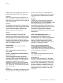
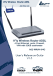
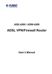
ADSL2+ Service Gateway HM410dp User Guide ADSL2+ Service Gateway HM410dp User Guide . Copyright Ericsson AB - 2004 All Rights Reserved Disclaimer No part of this document may be reproduced in any form without the written permission of the copyright owner. The contents of this document are subject to revision without notice due to continued progress in methodology, design, and manufacturing. Ericsson shall have no liability for any error or damages of any kind resulting from the use of this document. Abstract This document describes configuration and management of the Ericsson ADSL2+ Service Gateway HM410dp. Trademark List Windows Windows is a registered trademark of Microsoft Corporation All other brand and product names are trademarks or registered trademarks of their respective holders. ii 1553-ZAT 759 94 Uen A – October 2004 . Contents 1 Introduction 1 1.1 Structure of this Guide 1 1.2 Product Overview 1 2 Hardware Description and Installation 3 2.1 Before You Start 3 2.1.1 Package Contents 3 2.1.2 Subscription for ADSL Service 3 2.1.3 System Requirements 3 2.2 Physical Appearance 4 2.2.1 Front Panel and LED Indicators 4 2.2.2 Back Panel and Connectors 5 2.3 Placement of the HM410dp 6 2.4 Installation 7 3 Initial Configuration 9 3.1 Introduction 9 3.2 Access the Configuration Wizard 10 3.2.1 DHCP Routed (MER) 12 3.2.2 PPPoE Routed 12 3.2.3 Bridged 14 3.3 Access the Internet 15 4 Advanced Configuration 16 4.1 Introduction 16 4.2 Default Settings 17 4.3 Basic Setup 19 4.3.1 Start 19 4.3.2 Firmware Update 20 4.3.3 Health Check 22 1553-ZAT 759 94 Uen A – October 2004 iii Contents 4.3.4 Help 27 4.4 Advanced Setup 29 4.4.1 Password 29 4.4.2 Security 32 4.4.3 DHCP Server 44 4.4.4 Internet Access 50 4.4.5 UPnP 56 4.4.6 Save Config 57 4.4.7 Default Settings 58 4.4.8 Backup Restore Config 60 4.4.9 Log 62 5 Configuring PCs 63 5.1 Before You Begin 63 5.2 Obtaining Internet Information Automatically 63 5.2.1 Windows XP 63 5.2.2 Windows 2000 64 5.2.3 Windows Me 65 5.2.4 Windows 95, 98 66 5.3 Assigning Static Internet Information 67 Glossary iv 68 1553-ZAT 759 94 Uen A – October 2004 Introduction 1 Introduction This chapter tells you about the scope of this guide and gives a brief product overview. 1.1 Structure of this Guide This User Guide contains information that you will need to configure and manage the ADSL2+ Service Gateway HM410dp. The following chapters are included: 1.2 • Chapter 1 – “Introduction” – provides information about this guide and gives a brief product overview. • Chapter 2 – “Hardware Description and Installation” – provides a hardware description and detailed instructions about how to install the HM410dp. This is an extract from the “Quick Installation Guide” provided in the product package. • Chapter 3 – “Initial Configuration” – describes how to access the builtin Configuration tool and run the Configuration Wizard in order to perform the initial configuration. • Chapter 4 – “Advanced Configuration” – provides detailed information about how to perform configuration using the Advanced Setup options included in the configuration tool. • Chapter 5 – “Configuring PCs” – gives instructions for configuring the Internet settings on your computers to work with the HM410dp. • The Glossary includes abbreviations and explanations to technical terms used in this guide. Product Overview The HM410dp acts as an advanced home router. It comes with all the standard home router functions, such as NAT, a stateful firewall and a DHCP Server. Additionally, the HM410dp includes a fully featured SIP and IGMP Proxy, to enable voice and vide devices residing on the home network. The key benefits of the HM410dp are: 1553-ZAT 759 94 Uen A – October 2004 1 Introduction 2 • Top-notch ADSL2+ performance; HM410dp supports ADSL (G992.1) and the newer ADSL2 (G992.3) and ADSL2+ (G992.5) standards. • Quality of Service; Multiple PVCs and ATM level traffic shaping and policing, together with a learning bridge and static IP routes. 1553-ZAT 759 94 Uen A – October 2004 Hardware Description and Installation 2 Hardware Description and Installation This chapter describes the product and provides instructions about how to install the HM410dp in a PC/Windows environment. 2.1 Before You Start 2.1.1 Package Contents Check the contents of the package against the shipping contents checklist below. If any of the items is missing, please contact the dealer from whom the equipment was purchased. • ADSL2+ Service Gateway HM410dp • Power Supply adapter • Ethernet cable • ADSL Line cable • Table stand • Quick Installation Guide Note: 2.1.2 Your HM410dp package may also include other materials provided by your service provider. Subscription for ADSL Service To use the ADSL2+ Service Gateway HM410dp, you will require an ADSL service subscription from your broadband service provider. 2.1.3 System Requirements Computer(s) that will be connected to the HM410dp must meet the following requirements: • 10/100Base-T Network Interface Card (NIC) installed. • Operating system: Windows 95 or higher, Mac OS X, and Linux. 1553-ZAT 759 94 Uen A – October 2004 3 Hardware Description and Installation 2.2 Physical Appearance 2.2.1 Front Panel and LED Indicators The HM410dp is equipped with seven (7) status LED (Light Emitting Diode) indicators as shown in the illustration below. Figure 1 - Front Panel Indicators Although the LED functions depend upon the operational state of the device, each LEDs general purpose is described in the table below (from top to bottom). Table 1 4 General Description of LEDs Label Color Description ADSL Green On: ADSL connection is established. Blinking: Data transmission (activity) or training. LAN Green On: Ethernet connection to a LAN or single Ethernet client is established. Blinking: Data transmission (activity). Status Green On: Status OK. Blinking: System activity, for example saving configuration to flash memory. Power Green On: Power is on. 1553-ZAT 759 94 Uen A – October 2004 Hardware Description and Installation 2.2.2 Back Panel and Connectors The following figure illustrates the back panel of the HM410dp: Figure 2 - Back Panel of the HM410dp Description of connectors and buttons: Table 2 Description of Connectors and Buttons Label Description ADSL ADSL socket for connection to a splitter/filter of phone outlet. Ethernet Four Ethernet ports for connection to a PC, IP telephone, set-top box, and/or switch/hub. Reset Reset button (tiny hole) for resetting the HM410dp to factory default settings. Section 4.4.7.1 – “Reset Button” describes how a reset is done. 0|1 Power switch for turning power on or off. 12V AC 1.2A Power socket for connecting the power supply adapter. 1553-ZAT 759 94 Uen A – October 2004 5 Hardware Description and Installation 2.3 Placement of the HM410dp The HM410dp can be placed either in a horizontal or upright position on a flat surface (i.e. a table) as shown in the figures below: Note: Proper ventilation is necessary to prevent the product from overheating. Do not block or cover the slots and openings on the device, which are intended for ventilation and proper operation. Figure 3 - Alternative Placement for the HM410dp If you choose to place the HM410dp in an upright position, use the provided table stand and fit the 4 pins on the table stand into the holes on the bottom of the unit: Figure 4 - Mounting of the Table Stand 6 1553-ZAT 759 94 Uen A – October 2004 Hardware Description and Installation 2.4 Installation Follow the procedure below to make the physical cable connections to the HM410dp. Figure 5 shows an installation example that can be used as a reference. 4 1 3 2 Figure 5 - HM410dp Installation Example 1 Connect the ADSL Line Connect one end of the provided ADSL Line cable to the ADSL port on the HM410dp. Connect the other end to your ADSL service port (splitter/filter or phone outlet). 2 Connect Ethernet device(s) Attach the provided Ethernet cable to one of the ports marked Ethernet on the HM410dp. Connect the other end to an Ethernet port on a PC, Set-Top Box, IP telephone or Ethernet switch/hub. You can simultaneously use as many cables and ports that you need depending on available services and devices. 1553-ZAT 759 94 Uen A – October 2004 7 Hardware Description and Installation 8 3 Connect the Power adapter Connect the cable from the Power Adapter to the POWER socket on the HM410dp and then insert the plug into a power source. 4 Switch on the Power Switch on the power by turning the power switch to 1. 1553-ZAT 759 94 Uen A – October 2004 Initial Configuration 3 Initial Configuration This chapter describes how to access the built-in Configuration tool and run the Configuration Wizard in order to perform the initial configuration. 3.1 Introduction The HM410dp is an advanced ADSL router with several features and supported modes that make it ideal for advanced home networking. The HM410dp offers a Configuration Wizard that enables you to easily configure the HM410dp through a user friendly GUI. No special software is required on your PC to manage and operate the HM410dp. All you need is a web browser. In the Configuration Wizard you can select an Internet Access type that fits your needs. There are currently three pre-defined access types as shown in the table below where they are briefly described. Table 3 Description of Internet Access Types Connection Type Select Internet Access Type Connect using DHCP or fixed IP address (without a Username and Password). DHCP Routed (MER) Bridged Some operators provide Username and Password also for this type of connection, but the login procedure is in this case done from a web page or similar. Connect using PPPoE (sometimes called dial-up). This type of connection requires a Username and a Password. PPPoE Routed The HM410dp still offers the possibility for advanced users to set up special network scenarios themselves or to modify the existing ones. Refer to chapter 4 – “Advanced Configuration” for further information. 1553-ZAT 759 94 Uen A – October 2004 9 Initial Configuration 3.2 Access the Configuration Wizard Follow the steps below to access the built-in Configuration tool and start the Configuration Wizard. Note: Before performing the following steps make sure that all the steps in section 2.4 - ”Installation” has been performed. 1 Start your web browser and type http://192.168.1.1 (the IP address for the HM410dp) in the URL field and hit Enter. 2 To access the Configuration tool you have to login and the following window is displayed: 3 Type admin in both the “User name” and “Password” fields and click OK 10 1553-ZAT 759 94 Uen A – October 2004 Initial Configuration 4 The welcome page of the Configuration tool is displayed: 5 Click on the Configuration Wizard > button to display the start page of the wizard: Three types of Internet access can be setup through this wizard and each one is described in detail in the following subsections. 1553-ZAT 759 94 Uen A – October 2004 11 Initial Configuration 3.2.1 DHCP Routed (MER) The DHCP Routed (MER) access type means that the HM410dp operates as a bridge to the WAN while simultaneously operating as a router to the LAN. This access type is “Always on” meaning that you is automatically connected to your ISP whenever you use your Internet connection. The HM410dp automatically activates the NAT service and its internal DHCP server. PCs on the LAN will be assigned private IP addresses from the built-in DHCP server and the NAT service will route the traffic to/from the WAN. To configure the HM410dp for DHCP Routed (MER) access type, follow the steps below: 3.2.2 1 From the Start page, click the Configuration Wizard > button to display the following page: 2 Select DHCP routed (MER) and click the Next> button. The Confirm page for Internet access appears: 3 Click the Confirm Changes button to save your Internet access setting. PPPoE Routed The PPPoE (or dial-up) access type is used by the ISP to identify users and allow them access to the Internet. You have to enter a valid Username and 12 1553-ZAT 759 94 Uen A – October 2004 Initial Configuration Password provided by your ISP. Once you have entered your Username and Password within this Wizard, the HM410dp will automatically connect to your ISP whenever you use your Internet connection. The HM410dp automatically activates the NAT service and its internal DHCP server. PCs on the LAN will be assigned private IP addresses from the built-in DHCP server and the NAT service will route the traffic to/from the WAN. Note: If you already have PPPoE client software installed on your computer(s), you must uninstall it. This can be done after completing this wizard. To configure the HM410dp for PPPoE Routed access type, follow the steps below: 1 From the Start page, click the Configuration Wizard > button to display the following page: 2 Select PPPoE routed and click the Next> button. The following page appears: 3 Enter your ”Username” and ”Password” provided by your ISP and click the Next> button. The Confirm page for Internet access appears: 1553-ZAT 759 94 Uen A – October 2004 13 Initial Configuration 4 3.2.3 Click the Confirm Changes button to save your Internet access setting. Bridged By using this access type the HM410dp will act as a bridge, meaning that the routing functionality (Firewall, NAT, UPnP, etc) will be disabled. This access type is suitable if you only want to connect a single computer to the Internet and want to perform all special functionality in the computer instead of the built-in capabilities of the HM410dp. This access type is “Always on” meaning that you is automatically connected to your ISP whenever you use your Internet connection. Note: If your ISP uses PPPoE you must have a PPPoE client software installed on your PC. To configure the HM410dp for Bridged access type, follow the steps below: 14 1 From the Start page, click the Configuration Wizard > button to display the following page: 2 Select Bridged and click the Next> button. The Confirm page for Internet access appears: 1553-ZAT 759 94 Uen A – October 2004 Initial Configuration 3 3.3 Click the Confirm Changes button to save your Internet access setting. Access the Internet Your Internet Service Provider (ISP) may have provided you additional instructions (in the package or separately) about account setup, additional software installation, and/or Internet usage. In that case, please follow those instructions to complete your Internet connection setup. 1553-ZAT 759 94 Uen A – October 2004 15 Advanced Configuration 4 Advanced Configuration This chapter describes detailed information about the how to perform configuration using the Basic/Advanced Setup options. 4.1 Introduction The HM410dp offers the possibility for advanced users to set up special network scenarios themselves or to modify the existing ones. Follow the steps in section 3.2 – “Access the Configuration Wizard” to display the start page of the configuration tool: This is the first page that is displayed each time you log in to the configuration pages. The page shows an overview of the Current Configuration. The left-hand menu includes links to pages that allows you to configure your device. The menu is split into two separate lists; 16 1553-ZAT 759 94 Uen A – October 2004 Advanced Configuration • Basic Setup Contains entries that display general information about the device including links to pages that you are most likely to want to use. • Advanced Setup Contains entries that allow you to change the default settings on your device. Click on an individual menu entry to display a new page including information and/or configuration options. 4.2 Default Settings In addition to handling the DSL connection to your ISP, the HM410dp can provide a variety of services to your network. The device is preconfigured with default settings for use with a typical home or small office network. The table below lists some of the most important default settings; these and other features are described fully in the subsequent chapters. If you are familiar with network configuration, review these settings to verify that they meet the needs of your network. Follow the instructions to change them if necessary. If you are unfamiliar with these settings, try using the device without modification, or contact your ISP for assistance. 1553-ZAT 759 94 Uen A – October 2004 17 Advanced Configuration Note: Before you modify any settings, we strongly recommend that you contact your ISP prior to changing the default configuration. Table 4 18 Default Configuration Settings of the HM410dp Parameter Value LAN IP Address / Subnet Mask 192.168.1.1 / 255.255.255.0 DHCP Server Enabled with the following pool of IP addresses: 192.168.1.2 through 192.168.1.21 DNS Server 192.168.1.1 Default Gateway 192.168.1.1 NAT (Network Address Translation) Enabled 1553-ZAT 759 94 Uen A – October 2004 Advanced Configuration 4.3 Basic Setup The Basic Setup contains entries that display general information about the device including links to pages that you are most likely to want to use. 4.3.1 Start The Basic Setup > Start page displays useful information about the current configuration of your device: • First Time Settings This is the start point for the Configuration Wizard that leads you through the most important settings for your local Internet connection. • Current Configuration This part gives an overview of the current configuration regarding security and Internet access settings. 1553-ZAT 759 94 Uen A – October 2004 19 Advanced Configuration 4.3.2 Firmware Update The Basic Setup > Firmware Update page displays the current version of the firmware in the HM410dp and allows you to update the firmware if you have received a newer version. The firmware is a software program which is stored as read-only memory on your device. To transfer a new firmware file and update the HM410dp, follow the steps below: 20 1 Download the new firmware file to your local PC. 2 Click the Browse… button to locate the file. 3 Once you have selected the file to be installed, click Open. The file’s directory path is displayed in the “Update file:” field. 4 Click the Update Now> button. The device checks that the selected file contains an updated version of firmware and starts the installing procedure. The following window is displayed during the process: 1553-ZAT 759 94 Uen A – October 2004 Advanced Configuration 5 The installing procedure may take several minutes, after which you will be asked to restart the HM410dp: 6 Click the Restart button. The restart ensures that any new features provided by the firmware update become available to you. 7 When the restart is complete you will automatically be redirected to the Start page. Note: Installing a firmware update does not make any changes to your current settings, so your Internet connection will be unaffected by the update. 1553-ZAT 759 94 Uen A – October 2004 21 Advanced Configuration 4.3.3 Health Check The Basic Setup > Health Check page allows you to run a health check to test whether the Internet connection on your device is working properly. The health check runs a number of tests in order to diagnose any “health” problems with your device’s Internet access. If you need to contact your ISP, they may ask you to run the Health Check and describe the results to them. This page also provides you with a link to the DSL status page, which displays detailed information about your DSL connection. This page asks you to ensure that your device is connected to your phone line. See section 2.4 - ”Installation” To perform a Health Check, follow the steps below: 1 22 Click on the Perform Health Check > button. The following page confirms that the health check is currently running. 1553-ZAT 759 94 Uen A – October 2004 Advanced Configuration The Health Check may take up to three minutes to complete. 2 Once the health check has finished running, the Health Check: Complete page is displayed. The most important details displayed on this page are the Result, Test and Diagnostic information: − Result; tells you the overall result of the health check. − Test; if the health check fails, this tells you which test caused the failure. The first test that fails stops the health check completely – no other tests are run after the first failed test. If the health check is successfully completed, “User Diagnostics complete” is displayed. − Diagnostic; if the health check fails, this provides technical information about the likely cause of a health check failure. If a failure occurs, you will need to give this information to your ISP’s support team. If the health check is successfully completed, no diagnostic information is displayed. For example, if you run the Health Check on your device when the DSL port is not connected, the following information may be displayed: This page tells you that the result failed. The test that caused the health check to fail was the physical connection test. The diagnostic information displays details about the failure that you can pass on to your ISP support team. This page also contains links to the Start page (including current configuration information) where it may be worth checking the settings if the health check failed. 1553-ZAT 759 94 Uen A – October 2004 23 Advanced Configuration If you want to run the health check again, click on the Health Check link at the bottom of the page, or from the left-hand Basic Setup menu, click on Health Check. 4.3.3.1 DSL Status Page From the Health Check page you can click on the DSL Status link to display the following page: This page displays useful information about the status of your DSL connection, including: • 24 Operational mode; the current connected mode. Possible values displayed are: − Inactive (not connected) − Unknown (unrecognized mode) 1553-ZAT 759 94 Uen A – October 2004 Advanced Configuration − • • Name of the standard compliance used by the connection (for example G.dmt.BisPlus). State; the current state of the device. Possible values displayed are: − Idle (not connected or attempting to connect) − Handshake (hunting for a remote modem) − Training (remote modem has been found) − Showtime (connected to the remote modem) Trained transmit/receive bit rate; the transmit/receive rates of the device (in bits per second). Click on the DSL port configuration… link at the top of the DSL Status page. The following page is displayed: In addition to information about the status of your DSL connection (also displayed on the DSL Status page), this page displays the current attribute 1553-ZAT 759 94 Uen A – October 2004 25 Advanced Configuration settings for your DSL port and allows you to configure these settings. The DSL port is called port A1. Note: You should only edit your DSL port configuration if your ISP has told you to do so and/or if you are experienced in DSL attribute configuration. Once you have configured DSL port attributes, click on the Apply button. The page is refreshed and the device is updated with your DSL configuration changes. Clicking on the Reset button before you click on Apply will reset attribute values to their previous settings. You can also display and configure advanced DSL port attributes. At the top of the Port A1 Configuration page, click on the View advanced configuration ... The page displayed contains many advanced attributes: Note: 26 You should only edit your DSL port configuration if your ISP has told you to do so and/or if you are experienced in DSL attribute configuration. 1553-ZAT 759 94 Uen A – October 2004 Advanced Configuration Once you have configured advanced DSL port attributes, click on the Apply button. The page is refreshed and the device is updated with your DSL configuration changes. Clicking on the Reset button before you click on Apply will reset attribute values to their previous settings. 4.3.4 Help The Basic Setup > Help page displays an index of the help information that corresponds with each web page. You can click on the Help link on any web page in order to display further information about a specific topic on a specific page. However, you may prefer to display the Help text index in order to navigate through Help topics more easily. Each heading is a link to another help page. Click on a heading to display information about a specific page. For example, clicking on Security displays the Help: Security page. The same page is displayed by clicking on the Help link on the Security page itself. If you have clicked on a heading to display one of the help pages, the lefthand menu is replaced by the following: 1553-ZAT 759 94 Uen A – October 2004 27 Advanced Configuration To go back to the Help index page and display the menus for the setup pages, either click on the Back link provided or click the Back button in your browser. 28 1553-ZAT 759 94 Uen A – October 2004 Advanced Configuration 4.4 Advanced Setup The Advanced Setup contains entries that allow you to change the default settings on your device. 4.4.1 Password The Advanced Setup > Password page lets you restrict access to your device’s web pages using password protection. With password protection enabled, users must enter a username and password before gaining access to the web pages. Note: Enabling password protection does not affect access to the Internet, only to the HM410dp web pages. By default, password protection is enabled on your device, and the username and password set are as follows: • Username: admin • Password: admin 1553-ZAT 759 94 Uen A – October 2004 29 Advanced Configuration The password page displays the current status of password protection. To change your password settings, follow the steps below: 30 1 Click on the Change Password settings here… link to display the following page: 2 This page allows you to enable or disable password protection. Protection is already enabled by default. Click the Next> button to display the following page: 3 This page displays the current Username and Password settings. Type your own unique username and password in the relevant boxes. They can be any combination of letters or numbers with a maximum of 20 characters. The default setting uses admin for both the username and password. We recommend that you do not set the same character combination for both username and password. Click the Next> button and the following confirmation page is displayed: 1553-ZAT 759 94 Uen A – October 2004 Advanced Configuration 4 This page confirms that password protection is enabled and displays the username that will be required in order to access the web pages. If you are happy with these settings, click the Confirm Changes button. 5 Now you need to login to the web pages using your new username and/or password: 6 Enter your new Username and/or password and click the OK button. 1553-ZAT 759 94 Uen A – October 2004 31 Advanced Configuration 4.4.2 Security The Advanced Setup > Security page allows you to configure advanced security features that protect your network by blocking unwanted traffic from the Internet. If you simply want to connect from your local network to the Internet, you do not need to make any changes to the default Security configuration. You only need to edit the configuration if you wish to do one or both of the following: • Allow Internet users to browse the user pages on your local network (for example, by providing an FTP or HTTP server) • Play certain games which require accessibility from the Internet. By default the IP addresses of your LAN PCs are hidden from the Internet. All data sent from your LAN PCs to a PC on the Internet appears to come from the IP address of your device. In this way, details about your LAN PCs remain private. This security feature is called Network Address Translation (NAT). 32 1553-ZAT 759 94 Uen A – October 2004 Advanced Configuration 4.4.2.1 Firewall Settings The Firewall is by default disabled meaning that the configuration is set to allow all PCs on your network to contact all Internet web sites. You can configure HM410dp to block access to certain Internet Websites from some or all the PCs on your network. From the Advanced Setup menu, click on Security. The “Security State” part displays information about the security settings. To change the state of the Firewall select Enabled and click the Change State button. Note: To save the Firewall state permanently, you MUST perform a Save Config. From the left hand menu, select Advanced Setup > Save Config and then click the Save button. A new part named “Firewall Configuration” is now displayed on the Security page. Click on the link Configure Port Filters to create a port filter: 1553-ZAT 759 94 Uen A – October 2004 33 Advanced Configuration The port filters currently created are displayed, and if you want to delete any of them just click the Delete link. To add a new port filter, click the Add Filter link. The following page is displayed: Enter parameters according to the following: 34 • Source IP Address and Mask; If you wish to filter packets originating from a certain node or subnet, enter the IP address and subnet mask that identifies this node on the network. • Destination IP Address and Mask; If you wish to filter packets addressed to a certain node or subnet, enter the IP address and subnet mask that identifies that destination node on the Internet. The Mask field is disregarded if you leave it as 0.0.0.0. • Protocol; Select the protocol you want to use in the drop-down list. 1553-ZAT 759 94 Uen A – October 2004 Advanced Configuration • Source/Destination Port Range; Enter the starting and ending port numbers that identify the service that you want to filter, e.g. web service is on port 80 and FTP on port 21. • Direction; From the drop-down lists, choose whether to filter the packets that are incoming (In) or outgoing (Out) with respect to the interface. The action can be “Allow” or “Block”. When you have made your settings, click the Apply button. You will now return to the Port filter list where your new port filter is displayed. Note: 4.4.2.2 To save the port filters permanently, you MUST perform a Save Config. From the left hand menu, select Advanced Setup > Save Config and then click the Save button. Configuring NAT Security Certain network games, chat or file sharing software do not work with your default NAT setting. Your device knows the port, protocol and trigger information needed to allow access to the common applications listed below, but by default, access to them is disabled. Table 5 Common Applications Application TCP port number UDP port number Trigger required? E-mail 110, 25 N/A False News 119 N/A False MSN Messenger 1863 N/A False Yahoo! Instant Messenger 5050 5055 5100 N/A False AOL Instant Messenger 5190 N/A False Internet Relay Chat (IRC) 194 194 False 1720 N/A True N/A 1719 True 1731, 522 N/A False 544 7070 544 6770 False Netmeeting (h323) Real Audio 1553-ZAT 759 94 Uen A – October 2004 35 Advanced Configuration Application TCP port number UDP port number Trigger required? Ping N/A (ICMP) N/A (ICMP) False Web connections (HTTP, HTTPS) 80 443 N/A False 51210 N/A True DialPad N/A 51200 51201 True FTP 21 N/A False Telnet 23 N/A False Secure shell (SSH) 22 N/A False Windows Media Services 1755 1755 False Gnutella 6346 N/A False Kazaa 1214 N/A False Windows Terminal Server 3389 N/A False DNS N/A 53 False PPTP 1723 1723 False IKE (”Internet Key Exchange”) N/A 500 False LDAP 389 N/A False GRE N/A (GRE) N/A (GRE) False Databeam (T.120) 1503 N/A false You can allow access to a common application from a specific PC on your network by enabling it. For more information, see section 4.4.2.4 ”Configuring Internet Applications”. If you want to allow access to an application that is not included in the above list of common applications, you can create and enable a custom application. For more information, see section 4.4.2.5 - ”Configuring Custom Applications”. Before you can configure your default NAT settings, you must assign a unique name to each of the PCs on your network. See below. 36 1553-ZAT 759 94 Uen A – October 2004 Advanced Configuration 4.4.2.3 Assigning PC Names You must assign a name to each of the PCs on your network before you can enable access to common applications or create custom ones. This allows you to refer to PCs by name instead of IP address. 1 From the left-hand Advanced Setup menu, click on Security. 2 Click on Configure named PCs link (in the Virtual Server section) to display the following page: This page displays the names previously assigned to PCs on your network. To assign a name to an unnamed PC, click Add a new PC name. The following page is displayed: 3 Type a unique, meaningful name in the “PC name” text box, then type the IP address of the PC that you want to assign this name to. Click on the Next> button to display the confirmation page: 1553-ZAT 759 94 Uen A – October 2004 37 Advanced Configuration 4 If you are happy with the name that you have assigned to the IP address, click the Confirm Changes button. You will then return to the Security: PC Names page where your newly added PC name now appears: 5 To remove a PC name, click the link Remove a PC name. The following page is displayed: 6 Select the PC name you want to remove from the drop-down list and click the Next> button. A confirmation page is displayed where you click the Confirm Changes button to confirm the removal. Once you have assigned PC names, you can enable Internet access to applications as described in the following sections. 4.4.2.4 Configuring Internet Applications This section assumes that you have already assigned names to the PCs on your network as described in the previous section. You can enable/disable a specific Internet application in order to allow/block access to it via an individual PC. 1 38 From the left-hand Advanced Setup menu, click on Security. 1553-ZAT 759 94 Uen A – October 2004 Advanced Configuration 2 Click on the Enable/Disable Internet applications link (in the Virtual Server section) to display the following page: This page displays details about applications that are currently enabled. 3 Click on Enable an application here… to display the following page: 4 This page allows you to select which application you wish to enable for a specific PC. The “Application name:” drop-down list contains the following: 5 − The common applications that your device knows about. − Any custom applications that you have manually configured. Select the application and the PC that you want to enable access to and click the Next> button. The following confirmation page is displayed: 1553-ZAT 759 94 Uen A – October 2004 39 Advanced Configuration 4.4.2.5 6 If you are happy with your application configuration, click the Confirm Changes button. You will return to the Security: Enabled Applications page containing details about the applications that are currently enabled: 7 To disable an application, click the Disable an application here… link. The following page is displayed: 8 Select the application you want to disable from the drop-down list and click the Next> button. A confirmation page is displayed where you click the Confirm Changes button. Configuring Custom Applications If you want to enable access to an application that does not appear on your device’s default list, you can create a custom application. In order to create a custom application, you must know: 40 1 The protocol used by the application (e.g. TCP, UDP and so on). 2 The primary port or range of ports used by the application. 3 Whether the application requires a trigger and if so, the secondary port or range of ports used by the application. 1553-ZAT 759 94 Uen A – October 2004 Advanced Configuration 4 The address translation type used by the trigger. Your application provider or games manufacturer should provide you with these details. To create a custom application, follow the steps below: In this example configuration, a custom application called network game using TCP port 5555 is created. 1 From the left-hand Advanced Setup menu, click on Security. 2 Click on the Define custom applications link to display the following page: 3 This page displays details of previously created custom applications. Click Add a new custom application to display the following page: 4 Type a unique name for your custom application, and select the transport protocol from the “Transport” drop-down list. Click the Next> button and the following page is displayed: 1553-ZAT 759 94 Uen A – October 2004 41 Advanced Configuration 5 Type a port range by entering the start and end of the range in the two boxes provided. If you want to use a single port, enter the port number in the first box and leave the second box blank. Note: 42 You must ensure that the single port or range specified does not overlap with a port or range for an existing common or custom application. See the common port ranges listed in section 4.4.2.2 – “Configuring NAT Security”. 6 Select the address translation type (NONE, TCP, UDP or TCP and UDP) from the drop-down list. This controls the translation of binary IP addresses in the payload of a packet (the part containing data). Click the Next> button to display the confirmation page: 7 This page confirms you custom application configuration. If you are happy with the details displayed, click the Confirm Changes button. You will return to the Security: Custom Applications page containing details of the custom application that you have just created. 1553-ZAT 759 94 Uen A – October 2004 Advanced Configuration 8 To delete a custom application, click the Delete a custom application link. The following page is displayed: 9 Select the application you want to remove from the drop-down list and click the Next> button. A confirmation page is displayed where you click the Confirm Changes button. In order to access your custom application, you must first enable it. See section 4.4.2.4 - ”Configuring Internet Applications”. 1553-ZAT 759 94 Uen A – October 2004 43 Advanced Configuration 4.4.3 DHCP Server The Advanced Setup > DHCP Server page allows you to configure the built-in DHCP server. The HM410dp incorporates a DHCP server that dynamically assigns IP addresses and serves as a DNS server to the PCs on your LAN. By default there is one DHCP Server Subnet created for the LAN interface. The IP address range on the LAN interface is 192.168.1.2 through 192.168.1.21. Note: 4.4.3.1 By default the DHCP server is enabled on the private LAN interface but if you already have a DHCP server on your network you should disable this function. Enable/Disable the DHCP Server The current status of the DHCP server is displayed on the top of the DHCP Server page. If enabled (default) a Disable button is shown which you click on to disable the DHCP server. When the DHCP server is disabled the button shows Enable instead. 44 1553-ZAT 759 94 Uen A – October 2004 Advanced Configuration 4.4.3.2 DHCP Server Subnets To change the settings for a DHCP Server subnet, click the Edit link for the subnet you want to change. The following page is displayed: The upper part (“Edit Address”) of the window allows you to change the default LAN IP address and subnet mask of the HM410dp. If you want to do so, click the Change Address link to display the following page: Enter your new “IP address” and “Subnet mask” in the corresponding fields and click the Confirm Changes button. 1553-ZAT 759 94 Uen A – October 2004 45 Advanced Configuration Note: If you change the LAN IP address while connected through your Web browser, you will be disconnected. You must open a new connection by entering your new LAN IP address as the URL. In the lower part of the window you can change the settings for the subnet as described below: IP addresses to be available on this subnet lets you specify the range of IP addresses that can be assigned to PCs on your LAN. DNS server option information includes settings for the DNS server. You can check the “Use local host address as DNS server” box to use this host 46 1553-ZAT 759 94 Uen A – October 2004 Advanced Configuration as the default DNS. Or, you can uncheck the box and manually set up the DNS IP address in the “Primary/Secondary DNS server address”. The DNS server addresses will be passed to the DHCP clients along with the IP addresses. The DHCP clients use the DNS to map a domain name to its corresponding IP address and vice versa. Default gateway option information; The HM410dp always uses local host as default gateway. When you have entered the details for the DHCP Server Subnet configuration, click the Confirm Changes button. Use the Reset button to reset all settings to default settings. Note: To save your DHCP Server subnet configuration you MUST perform a Save Config to save the configuration to non-volatile memory. From the left hand menu, select Advanced Setup > Save Config and then click the Save button. 1553-ZAT 759 94 Uen A – October 2004 47 Advanced Configuration 4.4.3.3 Fixed Hosts If you want to assign a specific IP address to a device (e.g. a PC or a printer) on your LAN, you can create a fixed mapping between an IP address and the device’s MAC address. The lower part of the DHCP Server page includes settings for “Fixed Hosts”: To create a new mapping click the Create link to view the following page: 48 1553-ZAT 759 94 Uen A – October 2004 Advanced Configuration Enter the IP address you want to assign and the unique MAC address of the device. In the “Maximum lease time” field enter the time (in seconds) you want the network device to lease the IP address before it is reassigned. The default value is 86400 seconds (24 hours). Click the OK button to confirm your settings. You will now return to the DHCP Server page where your fixed mapping is displayed in the lower part of the window: To change any of the settings, enter the new ones and click the Confirm Changes button. If you want to delete a fixed mapping, tick the Delete box and click the Confirm Changes button. Note: To save confirmed settings you MUST perform a Save Config to save the configuration to non-volatile memory. From the left hand menu, select Advanced Setup > Save Config and then click the Save button. 1553-ZAT 759 94 Uen A – October 2004 49 Advanced Configuration 4.4.4 Internet Access The Advanced Setup > Internet Access page allows you to change the way that your device connects to the Internet. Your ISP determines what type of Internet access you should use and provides you with any information that you need in order to configure the Internet access to your device. Your device needs the following address information in order to access the Internet: • IP address and subnet mask; The IP address and subnet mask assigned to your WAN interface. • Default Gateway; The gateway address that identifies the ISP server through which your Internet connection will be routed. • DNS Servers; The Dynamic Name System (DNS) servers used by your ISP to map host names and IP addresses. In most cases, you will not need to configure your device with these addresses because your ISP is likely to use an Internet access type which automatically assigns addresses to your device. When running the Configuration Wizard these settings and addresses are automatically set when choosing one of the pre-defined Internet Access types. 50 1553-ZAT 759 94 Uen A – October 2004 Advanced Configuration 4.4.4.1 Editing a Service 1 From the left hand Advanced Setup menu, click on Internet Access. One of the following pages is displayed (depending on what Internet access type is currently defined): This page displays information about the external connections currently defined. 1553-ZAT 759 94 Uen A – October 2004 51 Advanced Configuration 2 Click the corresponding Edit link in the “Rfc1483 Settings” or “PPPoE Settings” column to make changes to a service. The following window is displayed for a service when running DHCP routed (MER) as access type: For this type of connection the Encapsulation method can be changed to be either “LlcBridged” or “VcMuxBridged”. If your Internet access type is set to PPPoE routed, the following page is displayed when clicking the corresponding Edit link: Here you can change your PPP Username and Password if your ISP has provided you new ones. 52 3 Make your changes and click the Confirm Changes button. 4 Click the corresponding Edit link in the “ATM Channel settings” column to change the ATM attributes for a connection. The following window is displayed: 1553-ZAT 759 94 Uen A – October 2004 Advanced Configuration 5 4.4.4.2 Enter the values provided by your ISP and click the Confirm Changes button. A short description of each value is provided in the online help by clicking the Help link. Deleting a Service When running DHCP routed (MER) or Bridged access types you can delete a service by doing the following: 1 Click the corresponding Delete link to delete a connection. The following window is displayed: 2 Confirm the removal by clicking the Delete button. Note: To save your changes (removal of a WAN connection) you MUST perform a Save Config to save the configuration to non-volatile memory. From the left hand menu, select Advanced Setup > Save Config and then click the Save button. 1553-ZAT 759 94 Uen A – October 2004 53 Advanced Configuration 4.4.4.3 Creating a new Service When running DHCP routed (MER) or Bridged access types you can create a new service by performing the following steps: 1 From the left hand Advanced Setup menu, click on Internet Access. Below the list of currently defined connections, click the Create new connection link to display the following page: 2 Enter a unique name for your new connection in the Description field and type the VPI/VCI settings that your ISP has provided. Also select an Encapsulation method from the drop-down list. Click on the Create button. 3 You will now return to the Internet Access page. Note: 54 To save the creation of your new WAN connection you MUST perform a Save Config to save the configuration to non-volatile memory. From the left hand menu, select Advanced Setup > Save Config and then click the Save button. 1553-ZAT 759 94 Uen A – October 2004 Advanced Configuration 4.4.4.4 Manual IP Setup When running DHCP routed (MER) as access type you can manually setup your Internet connection. Your ISP must then provide you with the following information: • The WAN IP address and subnet mask for your device. • The Internet Gateway address. • The primary and secondary DNS addresses. To manually setup your Internet access, perform the following steps: 1 From the left hand Advanced Setup menu, click on Internet Access. On the Internet Access page click the Static IP Setup link to display the following page: 2 Click in each box and type the relevant address information provided by your ISP and click the Confirm Changes button. 3 You will now return to the Internet Access page and your configuration is complete. 1553-ZAT 759 94 Uen A – October 2004 55 Advanced Configuration 4.4.5 UPnP The Advanced Setup > UPnP page allows you to enable/disable the UPnP function. Universal plug and play (UPnP) is a networking architecture that provides compatibility among networking equipment, software and peripherals of the 400+ vendors that are part of the Universal Plug and play Forum. UPnP works with wired or wireless networks and can be supported on any operating system. When UPnP is enabled it will help your programs to pass the NAT and it will also appear as a UPnP device on your network. Future programs will use this device for different purposes. Programs like MSN Messenger and a lot of network enabled games use UPnP. The current status (enabled/disabled) of UPnP and which port is used is displayed on this page. To disable UPnP click on the Disable button. 56 1553-ZAT 759 94 Uen A – October 2004 Advanced Configuration 4.4.6 Save Config The Advanced Setup > Save Config page allows you to save all current configurations to non-volatile memory. Most settings you apply on the pages in the configuration tool will take effect immediately and be saved to non-volatile memory. In case a manual save is necessary, this is noted in the graphical user interface as the following example: Notice: After <action> use Save Config to save it permanently. Click the Save button to save all settings. Note: Do not turn off your HM410dp while the configuration is being saved. A confirmation is shown when the configuration has been saved: 1553-ZAT 759 94 Uen A – October 2004 57 Advanced Configuration 4.4.7 Default Settings The Advanced Setup > Default Settings page allows you to reset your device to its default factory settings. The configuration settings of your device are stored in a configuration file. When you set up your device and access the web pages for the very first time, the configuration file contains a default factory configuration. If you do make changes to the default configuration but then wish to revert back to the original factory configuration, you can do so by resetting the device to factory defaults. Note: If you reset your device to factory defaults, all previous configuration changes that you have made are overwritten by the factory default configuration. To reset your HM410dp to default settings, follow the steps below: 1 58 The Default Settings page reminds you that the resetting to factory defaults cannot be undone – any changes that you have made to the basic settings will be lost. If you are happy with this, click in the “Confirm” box to tick it and then 1553-ZAT 759 94 Uen A – October 2004 Advanced Configuration click the Reset to Defaults button. The following page is displayed: 2 Once the reset is complete, the Start page is displayed. Note: 4.4.7.1 Resetting to defaults also resets the username and password to their default settings. If you have previously changed the username and password the “Connect to …” or “Enter Current Password” login box will be displayed. Once you have entered the default settings (admin, admin) and clicked OK , the Start page is displayed. Reset Button You can also reset the HM410dp to factory default settings using the Reset button (tiny hole) on the back panel of the unit. This method is used if you are unable to access the configuration pages. To reset the HM410dp using the Reset button, follow the steps below: 1 Power off the unit. 2 By using the tip of a pen press the Reset button and power on the unit. Keep the button pressed for at least four seconds. 1553-ZAT 759 94 Uen A – October 2004 59 Advanced Configuration 4.4.8 Backup Restore Config The Advanced Setup > Backup Restore Config page allows you to save a backup file of your current configuration and to restore your configuration from a previously saved file. 4.4.8.1 Backup Configuration To save a backup file of your current configuration proceed as follows: 1 Click on the Backup button and the following page is displayed: 2 In the “Save as” windows select a folder to save your configuration file in and click OK . The download starts. 3 When the downloading is complete close the window. Note: 60 Do not modify this configuration file since it then will be invalid and not accepted if you want to make a restore. 1553-ZAT 759 94 Uen A – October 2004 Advanced Configuration 4.4.8.2 Restore Configuration To restore your configuration from a previously saved file proceed as follows: 1 Click on the Browse… button to locate your backup file. 2 Once you have selected the file to be installed, click Open. The file’s directory path is displayed in the “Configuration File” field. 3 Click on the Restore button and the following window is displayed: 4 When the restoring is completed the following window appears: 5 Click the save link to save the configuration (otherwise the new settings are only valid until the next reboot). 1553-ZAT 759 94 Uen A – October 2004 61 Advanced Configuration 4.4.9 Log The Advanced Setup > Log page displays an error log. The most recent errors are listed at the bottom of the list and the “When” column shows the time in seconds since the last reboot of the HM410dp. Click the Clear Log button to clear the log. 62 1553-ZAT 759 94 Uen A – October 2004 Configuring PCs 5 Configuring PCs This chapter provides instructions for configuring the Internet settings on your computers to work with the HM410dp. 5.1 Before You Begin By default, the HM410dp automatically assigns the required Internet settings to your PCs. You need only to configure the PCs to accept the information when it is assigned. Note: 5.2 In some cases, you may want to assign Internet information manually to some or all of your computers rather than allow the HM410dp to do so. See section 5.3 – “Assigning Static Internet Information”. Obtaining Internet Information Automatically Follow the instructions that correspond to the operating system installed on your PC. 5.2.1 Windows XP 1 In the Windows task bar, click the Start button, and then click Control Panel. 2 Double-click on the Network Connections icon. 3 In the LAN or High-Speed Internet window, right-click on the icon corresponding to your network interface card (NIC) and click the Properties button. (Often, this icon is labeled Local Area Connection). The Local Area Connection dialog box is displayed with a list of currently installed network items. 4 Ensure that the check box to the left of the item labeled Internet Protocol TCP/IP is checked and click the Properties button. 5 In the Internet Protocol (TCP/IP) Properties dialog box, click the radio button labeled Obtain an IP address automatically. Also click the radio button labeled Obtain DNS server address automatically. 1553-ZAT 759 94 Uen A – October 2004 63 Configuring PCs 6 5.2.2 Click OK twice to confirm your changes, and then close the Control Panel. Windows 2000 First, check for the IP protocol and, if necessary, install it: 1 In the Windows task bar, click the Start button, point to Settings, and then click Control Panel. 2 Double-click the Network and Dial-up Connections icon. 3 In the Network and Dial-up Connections window, right-click the Local Area Connection icon, and then click the Properties button. The Local Area Connection Properties dialog box is displayed with a list of currently installed network components. If the list includes Internet Protocol (TCP/IP), then the protocol has already been enabled. Skip to step 10. 4 If Internet Protocol (TCP/IP) does not display as an installed component, click the Install… button. 5 In the Select Network Component Type dialog box, select Protocol, and then click the Add… button. 6 Select Internet Protocol (TCP/IP) in the Network Protocols list, and then click OK . You may be prompted to install files from your Windows 2000 installation CD or other media. Follow the instructions to install the files. 7 If prompted, click OK to restart your computer with the new settings. Next, configure the PCs to accept IP information assigned by the HM410dp: 8 In the Control Panel, double-click the Network and Dial-up Connections icon. 9 In the Network and Dial-up Connections window, right-click the Local Area Connection icon, and then click the Properties button. 10 In the Local Area Connection Properties dialog box, select Internet protocol (TCP/IP), and then click the Properties button. 11 In the Internet Protocol (TCP/IP) Properties dialog box, click the radio button labeled Obtain an IP address automatically. Also click the radio button labeled Obtain DNS server address automatically. 64 1553-ZAT 759 94 Uen A – October 2004 Configuring PCs 12 Click OK twice to confirm and save your changes, and then close the Control Panel. 5.2.3 Windows Me First, check for the IP protocol and, if necessary, install it: 1 In the Windows task bar, click the Start button, point to Settings, and then click Control Panel. 2 Double-click the Network and Dial-up Connections icon. 3 In the Network and Dial-up Connections window, right-click the Network icon, and then click the Properties button. The Network Properties dialog box is displayed with a list of currently installed network components. If the list includes Internet Protocol (TCP/IP), then the protocol has already been enabled. Skip to step 11. 4 If Internet Protocol (TCP/IP) does not display as an installed component, click the Add… button. 5 In the Select Network Component Type dialog box, select Protocol, and then click the Add… button. 6 Select Microsoft in the Manufacturers box. 7 Select Internet Protocol (TCP/IP) in the Network Protocols list, and then click OK . You may be prompted to install files from your Windows Me installation CD or other media. Follow the instructions to install the files. 8 If prompted, click OK to restart your computer with new settings. Next, configure the PC to accept IP information assigned by the HM410dp: 9 In the Control Panel, double-click the Network and Dial-up Connections icon. 10 In Network and Dial-up Connections window, right-click the Network icon, and then click the Properties button. 11 In the Network Properties dialog box, select TCP/IP, and then click the Properties button. 12 In the TCP/IP Settings dialog box, click the radio button labeled Server assigned IP address. Also click the radio button labeled Server assigned name server address. 1553-ZAT 759 94 Uen A – October 2004 65 Configuring PCs 13 Click OK twice to confirm and save your changes, and then close the Control Panel. 5.2.4 Windows 95, 98 First, check for the IP protocol and, if necessary, install it: 1 In the Windows task bar, click the Start button, point to Settings and then click Control Panel. 2 Double-click the Network icon. The Network dialog box displays with a list of currently installed network components. If the list includes TCP/IP, then the protocol has already been enabled. Skip to step 9. 3 If TCP/IP does not display as an installed component, click the Add… button. The Select Network Component Type dialog box displays. 4 Select Protocol, and then click the Add… button. The Select Network Protocol dialog box displays. 5 Click on Microsoft in the Manufacturers list box, and then click TCP/IP in the Network Protocols list box. 6 Click OK to return to the Network dialog box, and then click OK again. You may be prompted to install files from your Windows 95/98 installation CD. Follow the instructions to install the files. 7 Click OK to restart the PC and complete the TCP/IP installation. Next, configure the PC to accept IP information assigned by the HM410dp: 8 Open the Control Panel window, and then click the Network icon. 9 Select the network component labeled TCP/IP, and then click the Properties button. If you have multiple TCP/IP listings, select the listing associated with your network card or adapter. 10 In the TCP/IP Properties dialog box, click the IP Address tab. 11 Click the radio button labeled Obtain an IP address automatically. 12 Click the DNS Configuration tab, and then click the radio button labeled Obtain an IP address automatically. 13 Click OK twice to confirm and save your changes. You will be prompted you restart Windows. Click Yes to do so. 66 1553-ZAT 759 94 Uen A – October 2004 Configuring PCs 5.3 Assigning Static Internet Information If you are like most users, you will not need to assign static Internet information to your LAN PCs. Your ISP automatically assigns this information. In some cases however, you may want to assign Internet information to some or all of your PCs directly (often called “statically”), rather than allowing the HM410dp to assign it. This option may be desirable (but not required) if: • You have obtained one or more public IP addresses that you want to always associate with specific computers (for example, if you are using a computer as a public web server). • You maintain different subnets on your LAN. Before you begin, be sure to have the following information on hand, or contact your ISP if you do not know it: • The IP address and subnet mask to be assigned to each PC to which you will be assigning static IP information. • The IP address of the default gateway for your LAN. In most cases, this is the address assigned to the LAN port on the HM410dp. By default, the LAN port is assigned this IP address: 192.168.1.1. • The IP address of your ISP’s Domain Name System (DNS) server. On each PC to which you want to assign static information, follow the instructions in sections 5.2.1 through 5.2.4 relating only to checking for and/or installing the IP protocol. Once it is installed, continue to follow the instructions for displaying each of the Internet Protocol (TCP/IP) properties. Instead of enabling dynamic assignment of the IP addresses for the computer, DNS server and default gateway, click the radio buttons that enable you to enter the information manually. Note: Your PCs must have IP addresses that place them in the same subnet as the HM410dp LAN port. If you manually assign IP information to all your LAN PCs, you can follow the instructions in section 4.4.3.2 – “DHCP Server Subnets” to change the LAN port IP address accordingly. 1553-ZAT 759 94 Uen A – October 2004 67 Glossary Glossary Authorization The process of determining what types of activities a user is permitted to undertake. Usually, authorization is in the context of authentication: once you have authenticated a user, they may be authorized for different types of access or activity. Bridging Passing data from your network to your ISP and vice versa using the hardware addresses of the devices at each location. Bridging contrasts with routing, which can add more intelligence to data transfers by using network addresses instead. Broadband A telecommunications technology that can send different types of data over the same medium. DSL is a broadband technology. Broadcast To simultaneously send the same message to multiple recipients. DHCP - Dynamic Host Configuration Protocol DHCP automates address assignment and management. When a computer connects to the LAN, DHCP assigns it an IP address from a shared pool of IP addresses; after a specified time limit, DHCP returns the address to the pool. DNS - Domain Name System The DNS maps domain names into IP addresses. DNS information is distributed hierarchically throughout the Internet among computers called DNS servers. When you start to access a web site, a DNS server looks up the requested domain name to find its corresponding IP address. If the DNS server cannot find the IP address, it 68 communicates with higher-level DNS servers to determine the IP address. Domain name A domain name is a user-friendly name used in place of its associated IP address. Domain names must be unique; their assignment is controlled by the Internet Corporation for Assigned Names and Numbers (ICANN). Domain names are a key element of URLs, which identify a specific file at a web site. Download To transfer data in the downstream direction, i.e. from the Internet to the user. Encapsulation A technology that enables one network to send its data via another network’s connections. Encapsulation works by encapsulating a network protocol within packets carried by the second network. Encapsulation is also called tunneling. FTP - File Transfer Protocol A program used to transfer files between computers connected to the Internet. Common uses include uploading new or updated files to a web server, and downloading files from a web server. Host A device (usually a computer) connected to a network. HTTP - Hypertext Transfer Protocol HTTP is the main protocol used to transfer data from web sites so that it can be displayed by web browsers. Hub A hub is a place of convergence where data arrives from one or more directions and is forwarded out in one or more directions. It 1553-ZAT 759 94 Uen A – October 2004 Glossary usually includes a switch of some kind. It connects an Ethernet bridge/router to a group of PCs on a LAN and allows communication to pass between the networked devices. ICMP – Internet Control Message Protocol An Internet protocol used to report errors and other network-related information. The ping command makes use of ICMP. IP address The address of a host (computer) on the Internet, consisting of four numbers, each from 0 to 255, separated by periods, e.g. 192.168.1.1. An IP address consists of a network ID that identifies the particular network the host belongs to, and a host ID uniquely identifying the host itself on that network. A network mask is used to define the network ID and the host ID. Because IP addresses are difficult to remember, they usually have an associated domain name that can be specified instead. ISP – Internet Service Provider A company that provides access to the Internet. LAN – Local Area Network A computer network limited to the immediate area, such as a home, office, or small building. LED – Light Emitting Diode A type of control lamp on devices that indicates the status of the device. MAC address Short for Media Access Control address, the permanent hardware address of a device assigned by its manufacturer. MAC addresses are expressed as six pairs of hex characters (0-9 and A-f), with each pair separated by colons. For example: 1a:2b:23:5b:66:9a NAT - Network Address Translation A service performed by many routers that 1553-ZAT 759 94 Uen A – October 2004 translates your network’s publicly known IP address into a private IP address for each computer on your LAN. Only your router and your LAN know these addresses; the outside world sees only the public IP address when talking to a computer on your LAN. Network mask A network mask is a sequence of bits applied to an IP address to select the network ID while ignoring the host ID. Bits set to 1 mean “select this bit” while bits set to 0 mean “ignore this bit”. For example, if the network mask 255.255.255.0 is applied to the IP address 100.10.50.1, the network ID is 100.10.50, and the host ID is 1. NIC – Network Interface Card An adapter card that plugs into your computer and provides the physical interface to your network cabling, which for Ethernet NICs is tyically an RJ-45 connector. Packet Data transmitted on a network consists of units called packets. Each packet contains a payload (the data), plus overhead information such as where it came from (source address) and where it should go (destination address). Ping – Packet Internet (or Inter-Network) Groper A program used to verify whether the host associated with an IP address is online. It can also be used to reveal the IP address for a given domain name. Port In TCP/IP and UDP networks, an endpoint to a logical connection. The port number identifies what type of port it is. For example, port 80 is used for HTTP traffic. PPP – Point-to-Point Protocol A protocol for serial data transmission that is used to carry IP (and other protocol) data between your ISP and your computer. The 69 Glossary WAN interface on the HM410dp uses a form of PPP called PPPoE (PPP over Ethernet). Protocol A set of rules governing the transmission of data. In order for a data transmission to work, both ends of the connection have to follow the rules of the protocol. Routing Forwarding data between your network and the Internet on the most efficient route, based on the data’s destination IP address and current network conditions. A device that performs routing is called a router. Subnet A subnet is a portion of a network. The subnet is distinguished from the larger network by a subnet mask that selects some of the computers of the network and excludes all others. The subnet’s computers remain physically connected to the rest of the parent network, but they are treated as though they were on a separate network. Subnet mask A mask that defines a subnet. See also Network mask. TCP – Transmission Control Protocol See TCP/IP. TCP/IP – Transmission Control Protocol / Internet Protocol The basic protocols used on the Internet. TCP is responsible for dividing data up into packets for delivery and reassembling them at the destination, while IP is responsible for delivering the packets from source to destination. When TCP and IP are bundled with higher-level applications such as HTTP, FTP, Telnet, etc., TCP/IP refers to this whole suite of protocols. Telnet An interactive, character-based program used to access a remote computer. While HTTP 70 and FTP only allow you to download files from a remote computer, Telnet allows you to log into and use a computer from a remote location. Triggers Triggers are used to deal with application protocols that create separate sessions. Some applications, such as NetMeeting, open secondary connections during normal operations, for example, a connection to a server is established using one port, but data transfers are performed on a separate connection. A trigger tells the device to expect these secondary sessions and how to handle them. UDP – User Datagram Protocol A connectionless transport service that dispenses with the reliability services provided by the TCP. UDP gives applications a direct interface with IP and the ability to address a particular application process running on a host via a port number, without setting up a connection session. UPnP – Universal Plug and Play A networking architecture that provides compatibility among networking equipment. UPnP boasts device-driver independence and zero-configuration networking. Upstream The direction of data transmission from the user to the Internet. Virtual Server A server, usually a Web server, that shares computer resources with other virtual servers. In this context, the virtual part simply means that it is not a dedicated server – that is, the entire computer is not dedicated to running the server software. Instead of requiring a separate computer for each server, dozens of virtual servers can co-reside on the same computer. 1553-ZAT 759 94 Uen A – October 2004 Glossary VPI and VCI A VPI (Virtual Path Identifier) is an 8-bit field while VCI (Virtual Channel Identifier) is a 16bit field in the ATM cell header. A VPI identifies a link formed by a virtual path and a VCI identifies a channel w ithin a virtual path. In this way, the cells belonging to the same connection can be distinguished. A unique and separate VPI/VCI identifier is assigned in advance to indicate which type of cells follow. WAN – Wide Area Network Any network spread over a large geographical area, such as a country or continent. With respect to the HM410dp, WAN refers to the Internet. 1553-ZAT 759 94 Uen A – October 2004 71 Glossary 72 1553-ZAT 759 94 Uen A – October 2004 Ericsson AB www.ericsson.com Ericsson AB - 2004 All Rights Reserved 1553-ZAT 759 94 Uen A – October 2004