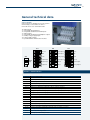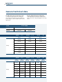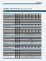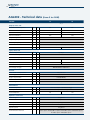
1
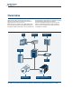
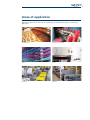
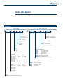
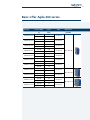
Agile
Advanced Standard Drive
Power, control
and green solutions
About us
3
Bonfiglioli, one name
for a large international group.
It was back in 1956 that Clementino Bonfiglioli
established in Bologna, Italy, the company that
still bears his name. Now, some fifty years later,
the same enthusiasm and dedication is driving
Bonfiglioli to become the world’s top name in
power transmission and control solutions.
Through directly controlled subsidiaries and
production plants around the world, Bonfiglioli
designs, manufactures and distributes a complete
range of gearmotors, drive systems and planetary
gearboxes, and boasts the most integrated
offering on the market today.
Now, to emphasise its commitment to health,
safety and environmental sustainability, Bonfiglioli
is adding the term “green” to the description of its
offering.
This commitment can be seen too in the Group’s
new trademark, made up of three shapes and
colours identifying Bonfiglioli’s three main business
areas - Power, Control & Green Solutions and
symbolising a set of values that includes openness
and respect for other cultures.
In a market in which excellent product quality
alone is no longer sufficient, Bonfiglioli also
provides experience, know-how, an extensive sales
network, excellent pre-sales and after-sales service
and modern communication tools and systems
to create high level solutions for industry, mobile
machinery and renewable energy.
Bonfiglioli
solutions
wind
industrial
mobile
photovoltaic
5
Innovative solutions
for industrial field.
Bonfiglioli Riduttori today is one of the top brands
in the power transmission industry.
The company’s success is the result of a business
strategy that relies on three fundamental factors:
know-how, innovation and quality.
The complete range of Bonfiglioli brand
gearmotors offers excellent technical
characteristics and guarantees the highest
performance. Substantial investment and technical
expertise have enabled the company to achieve an
annual production output of 1600000 units using
completely automated processes.
Certification of the company’s Quality System
by DNV and TÜV is proof of the high quality
standards achieved.
With the acquisition of the Vectron brand,
Bonfiglioli is now established as leader of the
industrial automation sector.
Bonfiglioli Vectron delivers products and services
for completely integrated inverter solutions.
These solutions complement Bonfiglioli’s power
transmission and control offering to the industrial
sector.
Since 1976, Bonfiglioli Trasmital’s know-how in
the power transmission industry has focused on
special applications offering 100% reliability in
the manufacturing of gearmotors for mobile
machinery.
This includes the full range of slew and wheel drive
applications and gearboxes for wind turbine pitch
and yaw drive systems.
Today Bonfiglioli Trasmital stands at the
forefront of the industry as a key partner to top
manufacturers worldwide.
Advanced
Standard Drive
7
Advanced technologies
for all industrial fields.
The new Agile Series of inverter drives from
Bonfiglioli sets new standards in technology for a
broad range of users. Agile drives are particularly
suited to the food & beverage, textile, wood,
packaging and ceramic industries, where they
can be used with a variety of medium complex
automation processes.
Agile inverter drives implement a sensorless
vector control algorithm that offers excellent
performance in speed and torque control. A wide
range of built-in functions deliver significant
benefits to users seeking safety, energy savings,
diagnostics, reliability and local intelligence.
The innovative user-friendliness of these drives is
evident from the word ‘go’. Even inexperienced
users will find installation and start-up quick and
easy.
Agile inverter drives are designed for reliability at
component, machine and process levels. Software
functions have been specially developed to inform
users of the ideal time to perform maintenance in
order to ensure continuous service from the plant.
Transparent control is ensured by Agile drives’
ability to accurately diagnose themselves and
surrounding components in order to avoid faults
and failures in the system.
Reliable and generous, Agile drives also boast
special functions designed to reduce programming
costs. These functions facilitate the selection and
setting of software parameters and provide a
speedy and intuitive man-machine interface.
The advanced energy saving functions, adaptability
and robustness of Agile inverter drives reduces
impact on the environment, too.
Integrated PLC functions allow Agile drives to
achieve a practical level of autonomy. The CPU not
only controls the motor, but also provides the user
with a number of programmable logic functions
that can be used to complement or replace PLC’s
and process controllers.
8
Overview
Agile inverter drives are designed to control
asynchronous induction motors and permanent
magnet synchronous servomotors.
With their sleek, compact cases, Agile drives have
been specially developed for maximum functional
integration. With a wide range of hi-tech functions
Line
choke
already built in, Agile drives are complete and fully
functional drives despite their small size.
Thanks to intelligent design, the generous and
advanced standard functions can be expanded
by accessories and optional modules to extend
versatility even further.
Additional
EMC filter
Communication
modules
Breaking
resistance
Resource
pack
Asynchronous
induction motor
Sensorless permanent
magnet synchronous motor
The Agile Series comes in three book-size models covering power requirements from 0.25 to 11 kW.
9
Areas of application
Agile inverter drives can be used in all areas of industry, but are particularly suited to the following
applications:
Food & Beverage
Vertical stocking system
Textile
Wood
Packaging
Ceramics
10
Agile 402 series
Selection guide
To order an Agile inverter drive, you need to
specify the designation string corresponding to
it. This comprises a series of fields that define
exactly and uniquely what drive you need for your
particular application. The first five fields identify
the drive and its basic variants. These fields must
be mandatorily compiled in your order. You cannot
leave any of these fields blank.
The next four fields on the other hand define
optional configurations for your drive. To do
without any of these options, simply leave the
corresponding field blank.
Designation
Basic variants
AGL 402
18
2
Optional variants
F
A
MPSV
CMPDP
Design version
A standard cooling
(default)
C Cold Plate
Size 1
02 0.25 kW
03 0.37 kW
05 0.55 kW
07 0.75 kW
09 1.1 kW
11 1.5 kW
13 2.2 kW
Size 2
15 3.0 kW
18 4.0 kW
Series
AGL 402 inverter 3ph 320-530 V ± 10%
Size 3
19 5.5 kW
21 7.5 kW
22 9.2 kW
23 11 kW
SW
Software arrangement
(blank) standard (default)
S
Safe torque off
EMC filter
Fintegrated
(default)
Size
1 size 1
2 size 2
3 size 3
RP
Memory extension
(blank) no card (default)
RP
Resource Pack installed
Communication modules
(blank)
no module (default)
CM-CAN
CANopen interface
CM-PDP
Profibus DP interface
CM-232
RS232 interface
CM-485
RS485 interface
CM-DEV
DEVICENET interface
CM-EtherCATEtherCAT® interface
CM-ProfiNet
PROFINET interface
CM-VABus/TCP Ethernet VA BUS TCP interface
Mounting kit
(blank) panel fixing (default)
MPSV
feed-through no fan
MDIN
DIN rail (size 1 only)
MNVIBanti-vibration
11
Agile 202 series
Designation
Basic variants
AGL 202
13
1
Optional variants
F
A
MPSV
CMPDP
Design version
A standard cooling
(default)
C Cold Plate
3ph 230V
Size 1
02 0.25 kW
03 0.37 kW
05 0.55 kW
07 0.75 kW
09 1.1 kW
11 1.5 kW
13 2.2 kW
1ph 230V
Size 1
02 0.12 kW
03 0.18 kW
05 0.25 kW
07 0.37 kW
09 0.55 kW
11 0.75 kW
13 1.1 kW
Size 2
15 3.0 kW
18 4.0 kW
Size 2
15 1.5 kW
18 2.2 kW
Series
AGL 202 inverter 1ph/3ph 200-240 V ± 10%
Size 3
19 5.5 kW
21 7.5 kW
Size 3
19 3 kW
21 3 kW
SW
Software arrangement
(blank) standard (default)
S
Safe torque off
EMC filter
Fintegrated
(default)
Size
1 size 1
2 size 2
3 size 3
RP
Memory extension
(blank) no card (default)
RP
Resource Pack installed
Communication modules
(blank)
no module (default)
CM-CAN
CANopen interface
CM-PDP
Profibus DP interface
CM-232
RS232 interface
CM-485
RS485 interface
CM-DEV
DEVICENET interface
CM-EtherCATEtherCAT® interface
CM-ProfiNet
PROFINET interface
CM-VABus/TCP Ethernet VA BUS TCP interface
Mounting kit
(blank) panel fixing (default)
MPSV
feed-through no fan
MDIN
DIN rail (size 1 only)
MNVIBanti-vibration
12
Basic offer Agile 402 series
Inverter
Power supply
Power
Filter
[V]
[kW]
AGL402-02 1 F A
3ph 400
0.25
Integrated
AGL402-03 1 F A
3ph 400
0.37
Integrated
AGL402-05 1 F A
3ph 400
0.55
Integrated
AGL402-07 1 F A
3ph 400
0.75
Integrated
AGL402-09 1 F A
3ph 400
1.1
Integrated
AGL402-11 1 F A
3ph 400
1.5
Integrated
AGL402-13 1 F A
3ph 400
2.2
Integrated
AGL402-15 2 F A
3ph 400
3.0
Integrated
Dimensions
[HxDxW]
200 x 170 x 60
200 x 196 x 80
AGL402-18 2 F A
3ph 400
4.0
Integrated
AGL402-19 3 F A
3ph 400
5.5
Integrated
AGL402-21 3 F A
3ph 400
7.5
Integrated
200 x 205 x 125
AGL402-22 3 F A
3ph 400
9.2
Integrated
AGL402-23 3 F A
3ph 400
11
Integrated
13
Basic offer Agile 202 series
Inverter
AGL202-02 1 F A
AGL202-03 1 F A
AGL202-05 1 F A
AGL202-07 1 F A
AGL202-09 1 F A
AGL202-11 1 F A
AGL202-13 1 F A
AGL202-15 2 F A
AGL202-18 2 F A
AGL202-19 3 F A
AGL202-21 3 F A
Power supply
Power
[V]
[kW]
3ph 230
0.25
1ph 230
0.12
3ph 230
0.37
1ph 230
0.18
3ph 230
0.55
1ph 230
0.25
3ph 230
0.75
1ph 230
0.37
3ph 230
1.1
1ph 230
0.55
3ph 230
1.5
1ph 230
0.75
3ph 230
2.2
1ph 230
1.1
3ph 230
3.0
1ph 230
1.5
3ph 230
4.0
1ph 230
2.2
3ph 230
5.5
1ph 230
3
3ph 230
7.5
1ph 230
3
Filter
Dimensions
[HxDxW]
Integrated
Integrated
Integrated
Integrated
200 x 170 x 60
Integrated
Integrated
Integrated
Integrated
200 x 196 x 80
Integrated
Integrated
200 x 205 x 125
Integrated
14
Innovation at the service of people
Agile inverter drives help bridge the gap between
user and process by providing software and
hardware functions that simplify the management
of complete systems.
USER
PROCESS
Agile inverter process drives provide accurate
sensorless vector control of asynchronous induction
motors and permanent magnet synchronous
motors, and also help manage the complete
automation system by contributing to energy
saving, safety, maintenance and logic control.
Agile drives are Bonfiglioli’s solution to the needs
of the standard drive market, and boast a special
“all-in-one” formula that delivers exceptional
versatility.
Easy start up mode
Leader in room saving
Energy stand-by
Integrated automation
Safety inside
Sensorless brushless control
Diagnostic fault scanner
Resource pack
Downtime suppressor
E-served
15
Innovation at the service of people
Rapidity
It only takes a few minutes to install and set up an
Agile drive. Users will find everything quick and
easy, from control rack installation to software
configuration, and will have the motor up and
running in next to no time.
Energy saving
Agile helps reduce system energy requirements by
minimising its own losses and those of the motor.
Functional safety
Agile drives respect all the safety standards
applicable to electronic variable speed control.
In particular, Agile drives provide functional
safety according to EN61508 SIL2 and electrical
safety according to EN954-1 Cat. 3, in conformity
to EN61800-5-2 product standards for torque
elimination through the physical disconnection of
the motor inside the inverter.
Diagnostic analysis
Agile drives provide valuable support for the
analysis of critical events affecting the drive itself
and the system in which it is installed. They also
incorporate a tool for monitoring, reconstructing
and interpreting system dynamics.
Failure prevention
Agile drives keep themselves and the system
they are installed in under control, and make a
generous contribution to maintenance efficiency
by preventing unexpected machine stoppages.
•Drilling template
•DIN rail mounting
•Clearly identified power terminals
•Pre-calibrated for Bonfiglioli motors
•Automatic and permanent adaptive tuning
•Pre-selection of application masks
•Customisable units of measure
•On-line help
•Sensorless control of permanent magnet
synchronous motors
•Automatic suspension of power stage with motor
stopped
•Adaptation of voltage to suit the load applied to
the motor shaft
•Minimum earth leakage
•Safe Torque Off
•Foolproof wiring
•Alarm log
•Drive and motor status recovery
•Autodiagnostics after critical events
•Built-in multi-trace oscilloscope
•Estimation of capacitor maintenance intervals
•Estimation of cooling fan maintenance intervals
16
Innovation at the service of people
Space saving
The compact book size of Agile drives means
significant space saving and great manoeuvrability
inside the control cabinet.
Built-in PLC
Agile drives can perform simple and complex
programmable logic operations on physical
signals to their terminals and on internal software
variables, and can combine these operations to
create a functional program that can complement
or replace a control panel PLC.
•High power concentration
•Space saving in the control panel
•Book size
•Side by side installation
•Same height for all sizes
•Programmable logic functions
•Graphic block programming
•Cyclical operating system
•Accessible drive variables
•Input/output buffers
Sensorless brushless
Agile vector drives can control even sensorless
permanent magnet synchronous motors thanks
to an innovative algorithm which provides full
starting torque.
Resource pack
Agile drives can be fitted with an MMC standard
non-volatile flash memory expansion.
E-served management
Agile can be fully managed through Bonfiglioli’s
MOSAICO e-business platform that lets you select
drives, order them and monitor delivery over the
internet.
•MMC standard memory expansion card
•Any capacity cards supported
•Parameter copy function
•Integrated application documentation
•Integrated application software
Technical training is also available through
Bonfiglioli’s HUB e-learning system. There is
even a dedicated website for the distribution of
newsletters.
17
Synergy with Bonfiglioli motors
To set up a modern microprocessor drive, the
electrical data of the motor have to be known for
the drive’s speed and torque control to use the
right mathematical model for calculating control
values.
To facilitate start-up and avoid the user having
to find and then manually enter all the necessary
data, Agile drives come with all the characteristics
of equivalent Bonfiglioli motors pre-programmed.
The drive loads these as default values into the
parameters that can be viewed using the built-in
display or VPlus software.
The first time you switch the drive on, the motor
parameter section will display a pre-programmed
list of numeric values ready for use with Bonfiglioli
motors. To use the drive with another motor,
simply modify these parameters as required during
the start-up procedure.
Bonfiglioli default motor data
A table of correspondence can be defined between
each Agile drive size and the Bonfiglioli 4-pole
Inverter
Power
supply
Asynchronous motor Nominal power
[V]
AGL202-02 1 F A
AGL202-03 1 F A
AGL202-05 1 F A
AGL202-07 1 F A
AGL202-09 1 F A
AGL202-11 1 F A
AGL202-13 1 F A
AGL202-15 2 F A
AGL202-18 2 F A
AGL202-19 3 F A
AGL202-21 3 F A
asynchronous or permanent magnet synchronous
motor for which the drive is ready for use.
Inverter
Asynchronous motor Nominal power
[kW]
1ph 230V
BN63B4 / M05A4
0.12
3ph 230V
BN71A / M05B4
0.25
1ph 230V
BN63B4 / M05B4
0.18
3ph 230V
BN71B4 / M1SD4
0.37
1ph 230V
BN63C4 / M05B4
0.25
3ph 230V
BN80A4 / M1LA4
0.55
1ph 230V
BN71B4 / M1SD4
0.37
3ph 230V
BN80B4 / M2SA4
0.75
1ph 230V
BN80A4 / M1LA4
0.55
3ph 230V
BN90S4 / M2SB4
1.1
1ph 230V
BN80B4 / M2SA4
0.75
3ph 230V
BN90LA / M3SA4
1.5
1ph 230V
BN90S4 / M2SB4
1.1
3ph 230V
BN100LA4 / M3LA4
2.2
1ph 230V
BN90LA4 / M3SA4
1.5
3ph 230V
BN100LB4 / M3LB4
3.0
1ph 230V
BN100LA4 / M3LA4
2.2
3ph 230V
BN112M4 / M3LC4
4.0
1ph 230V
BN100LB4 / M3LB4
3.0
3ph 230V
BN132S4 / M4SA4
5.5
1ph 230V
BN100LB4 / M3LB4
3.0
3ph 230V
BN132MA4 / M4LA4
7.5
[kW]
AGL402-02 1 F A
BN63C4 / M05B4
0.25
AGL402-03 1 F A
BN71B4 / M1SD4
0.37
AGL402-05 1 F A
BN80A4 / M1LA4
0.55
AGL402-07 1 F A
BN80B4 / M2SA4
0.75
AGL402-09 1 F A
BN90S4 / M2SB4
1.1
AGL402-11 1 F A
BN90LA4 / M3SA4
1.5
AGL402-13 1 F A
BN100LA4 / M3LA4
2.2
AGL402-15 2 F A
BN100LB4 / M3LB4
3.0
AGL402-18 2 F A
BN112M4 / M3LC4
4.0
AGL402-19 3 F A
BN132S4 / M4SA4
5.5
AGL402-21 3 F A
BN132MA4 / M4LA4
7.5
AGL402-22 3 F A
BN132MB4 / M4LB4
9.2
AGL402-23 3 F A
BN160MR4 / M4LC4
11
18
VPlus engineering software
VPlus software provides a common programming and
monitoring platform for all Bonfiglioli inverter drives.
Now in version 7, VPlus provides an effective aid to
configuring, diagnosing and controlling your drive
from a PC, and also provides a range of practical
tools to manage the resources of your AgilE
inverter completely and efficiently.
Just connect the computer to the drive via the
ASK-USB accessory cable and launch VPlus. Serial
communications are quickly established and entire
drive setup is displayed on the computer monitor along
with a toolbar containing drive control functions.
VPlus supports multiple and simultaneous
communications between the same number of drives
as there are USB ports on the computer, as well as a
connection to the Bonfiglioli drive field bus.
VPlus functions
Simply click on the relevant icons to:
• Upload parameter files to the drive
• Configure drive parameters
• Read current parameters values
• Run the motor setup
• Open the inverter monitoring window
• Display the 4-trace oscilloscope
• Open the inverter status window
• Program the drive’s built-in PLC
Each of the above functions opens a new window that remains visible along with
all the others to permit a global view of drive functions.
Graphic control panel
Current drive functioning values can be displayed numerically or graphically, as
the user wishes.
IO monitoring
The IO monitor window lets you view the inverter’s digital inputs and outputs
and motor status.
Built-in oscilloscope
VPlus software incorporates a digital oscilloscope with the following functions:
• 4 programmable traces
• 2 ms sampling rate
• manual/automatic X-Y axis scaling
• programmable threshold triggers
• auxiliary cursors
• print function
• data export in CSV format
• image saving
The oscilloscope enhances the functionality of the Agile drive’s own diagnostics
by permitting the run-time display of any physical or virtual variable handled
by the drive and the real time analysis of the entire process driven by the motor
shaft.
19
VPlus engineering software
Comparative analysis
To make it easier for users to analyse application
parameters off-line, VPlus also provides a file
compare function that identifies differences and
similarities.
On-line help
To guide users in programming the drive, VPlus also
features an on-line help that explains the meaning
and the effect of each drive parameter. Simply click
on the desired parameter to access help on it.
Application masks
To help users set up the drive for frequent
applications quickly and easily, VPlus includes a
library of application masks showing only those
software parameters that are strictly necessary for
application start-up.
Users benefit from a schematic description of the
functionalities provided by the selected mask as well
as the parameters needed to configure it.
Built-in graphic PLC
The internal PLC of Agile drives can be programmed
using VPlus software. The various functional blocks
processed by the PLC’s operating system can be
programmed in VPlus simply by selecting the
corresponding page.
A graphic editor in VPlus lets you load and drag all
the logic blocks recognised by the drive to form the
functional program that the PLC needs to implement
in RUN mode.
20
Sensorless control of permanent
magnet synchronous motors
In brushless motor control, the exact angular
position of the rotor must be known at all times
for the drive to commutate the inverter phases.
The conventional method for tracking rotor
position is to incorporate an encoder or resolver
inside the servomotor to provide the drive with the
necessary electrical signals. This, however, requires
extra cabling, data interfaces and controls.
Thanks to innovative technology, Agile drives can
control brushless servomotors without the need
for sensors, eliminating the cost of superfluous
components, wiring, interfaces and controls. Agile
drives use efficient algorithms to calculate the
instantaneous angular position of the motor shaft
from measurements of the current absorbed by
the motor. This gives significant savings in costs,
eliminates the criticalities inherent in sensors,
simplifies the control system and reduces energy
consumption by permitting a more efficient motor
architecture to be used.
By combining analytic techniques to reconstruct
the electrical status of the motor and functional
analyses of its magnetic circuit, Agile drives
provide effective vector control of torque.
Agile
Speed or
torque
reference
Vector
control
PWM
Calculated
position
Power
Sensorless
PMSM
Position
reconstruction
Power
NO feedback
Agile
Servomotor
Speed
Torque
21
Energy saving
Energy saving is a common objective in all areas of
manufacturing. No company is exempt from the
need to save money and help the environment at
the same time.
If energy saving is your aim, Agile is the drive to
help you achieve it.
AgileE drives incorporate numerous functions for
reducing the electrical energy needed to power
motors and can make a major contribution to
energy saving in any plant.
Bonfiglioli knows exactly what factors determine a
drive’s energy efficiency and how to achieve major
energy savings. Now all this know-how has been
concentrated into a single product.
Sensorless control of permanent magnet
synchronous motors
Modern brushless motors are extremely efficient
thanks to a design that favours excellent
electromechanical energy conversion and
minimises heat loss through the rotor.
Agile drives are designed to bring the benefits of
brushless motor technology within the reach of all
users.
Agile drives do not need encoders or resolvers
on board the motors to control them. They can
therefore save money by eliminating superfluous
components, without any loss of dynamic motor
performance.
Standby mode
Motors are often used in applications involving
intermittent functioning cycles characterised by
alternating run and rest phases. Under conditions
like these, the drive itself has to remain powered
on in order to be ready to start the motor as soon
as the application demands.
To avoid unnecessary energy consumption during
motor rest periods without actually disconnecting
power to the inverter, Agile drives use a special
auto-standby function, which leaves the inverter
in a “sleep” condition with only its control circuits
active, a condition in which energy consumption is
minimal. A programmable delay can be adjusted
by users in order to extend the standby mode even
to keypad display. As soon as a start command is
received, the inverter “wakes up” immediately to
power the motor.
Kinetic status
of MOTOR
Motor rest period
Energy status
of INVERTER
Operating status
LOW CONSUMPTION status
Power managing
Motor efficiency is significantly conditioned by the
quality of the power supply.
Agile drives use control to reduce motor voltage
to suit applied loads without compromising
performance. This reduces motor losses,
Torque required
by motor shaft
Voltage applied
to motor
Minimum earth leakage
Agile drives are equipped with a built-in, low
leakage current EMC filter that conforms to all
Operating status
consumption and maintenance requirements and
helps extend motor life. For example, if the motor
is run up to rated speed at zero load, there is no
need to apply full rated voltage. The minimum
voltage compatible with the needs of motor
magnetisation is all that is needed.
Motor at zero load
Minimum voltage
Motor at zero load
Minimum voltage
applicable standards. By significantly reducing
earth leakage, this filter also maximises energy
savings under all operating conditions.
22
A drive with a PLC built in
Modern PLCs are extremely evolved devices
with high calculation and interface capacities.
The problem is that they need qualified, expert
personnel to convert the needs of the machine
into sequences of PLC instructions. These may
even have to be encoded according to different
proprietary programming standards.
The inverter is becoming one type of actuator to
which PLCs can delegate the dynamic control of
an axis in synchronisation with other parts of the
machine.
Agile drives guarantee efficient motor control
and incorporate a programmable logic controller
that can be used to complement or replace a
conventional control panel PLC.
In the heart of every Agile drive is a PLC capable
of performing multiple logic operations (AND, OR,
XOR) and functions (counters, timers, comparators,
multiplexers, decoders, oscillators, etc.). These
can be combined using a graphic editor to create
complex functions. The result is an intelligent
local controller capable of handling the drive’s
own internal variables (currents, frequencies,
machine statuses, etc.), I/O signals to and from the
terminals, and multiplexed data exchanged over a
field bus.
The intuitive graphic editor allows even nonexpert users to program the PLC of an Agile drive
without having to learn complicated programming
languages that very few can master. Agile users do
not have to rely on others to program their drives.
Agile drives are powerful and intelligent and, by
relieving the main control panel PLC of local tasks,
conform perfectly to the concept of distributed
logic.
The Agile PLC recognises and handles 120
different functions, which can be used within 32
programmable functional modules (indexes).
Each module has a maximum of 4 inputs, 2 outputs
and 2 configuration parameters. When the drive
is switched on, its operating system indexes all the
active modules in sequence, taking only 1 ms per
module. Each module is implemented by running
all its instructions in sequence. When one module
has been completed, the OS moves on to the next,
and so on.
Function
selector
Inputs
Internal PLC
Function Block
Routine
Software
Parameters
Outputs
23
A drive with a PLC built in
The OS scans input and output buffers, samples
input signals and executes output signals before it
indexes the sequence of active modules.
Active function blocks
Instructions
Inactive
function blocks
Input Latches & Output Latches
Write
output buffer
24xx
25xx
Update
input buffer
20xx
23xx
Function
block 1
Function
block 2
Function
block 3
P1343 = 0
1. ms
5. ms
...
I=1
I=2
I=3
I=4
2. ms
6. ms
...
3. ms
7. ms
...
4. ms
8. ms
...
(Return)
CYCLE
As in any control panel PLC, cycle management
is entrusted to the operating system and is
independent of all other processes managed by
the CPU.
The program is therefore deterministic and scan time
proportional to the number of active function blocks.
In any automation process, the cycle period can be
calculated by summing the 1-ms delays introduced
by each function block.
Agile PLC functions can be programmed using
VPlus software, which graphically displays the
program to which the drive’s memory corresponds
in real time.
VPlus software also provides a page that can be
used to load graphic function blocks and link them
together to create complex logic networks for use
by the drive.
The Agile PLC supports and processes all the
variables used by the drive software, including I/O
variables, strings exchanged over the field bus and
numeric motor control values. The PLC is therefore
perfectly able to exchange signals with external
devices like sensors, actuators, inverters, PLCs, PC’s,
etc.) as well as with the drive itself.
Agile
External
devices
I/O
PLC area
Motor
control
routine
Field bus
External
devices
24
Integrated safety thanks to Safe Torque Off
The Machinery Directive establishes the safety
requirements that all machines must conform
to before they can carry the CE mark and be
manufactured and sold within the European
Community.
In particular, all machine movements must
be monitored by a safety system capable of
intervening in an emergency to stop motors
and disconnect power until normal operating
conditions can be restored.
Safety systems must intervene effectively and
guarantee physical disconnection between motor
and power source. They must also be reliable, i.e.
never fail to function.
Standards EN 954-1 and EN 61508 regulate safety
system effectiveness and reliability respectively.
These standards assign two distinct value scales to
effectiveness and reliability (Category and Level),
ensuring that machine manufacturers design in
a degree of safety adequate to the needs of the
application.
In a conventional drive, to guarantee the effective
disconnection of the motor and the absence of
turning moment at its shaft, the safety system uses
remote power switch outside the drive to insulate
the motor electrically.
Machine control
Power
supply
Generic
drive
M
Conventional safety system
Bonfiglioli has integrated the Safe-Torque-Off
system (STO, EN61800-5-2) in Agile drives in
response to market demand to reduce the size of
control panels, minimise the number of operating
components, simplify control, and eliminate the
mechanical stress caused by the sudden application
of the brake while the shaft is still turning. In
an emergency this system disconnects the motor
in compliance with EN13849 and EN61508 SIL2,
without the need for external contactor.
Machine control
Power
supply
M
Integrated functional safety
conforming to EN61508 level SIL 2
Integrated electrical safety
conforming to EN13849
Safety system implemented by an Agile drive
25
Integrated safety thanks to Safe Torque Off
Agile drives incorporate redundant functional
logic and hardware architecture to disconnect
the motor safely and stop it in the minimum time
possible.
The simultaneous activation of two digital inputs,
STOA and STOB, corresponding to two identical
but distinct electrical paths, causes the software
to recognise an external emergency condition,
suspend the generation of PWM pulses and
physically disable the optoisolators that transmit
signals to the IGBT drivers, all in less than 10ms.
This brings the motor to a controlled stop,
followed by total isolation from the inverter.
Any alarm condition arising inside the drive also
generates an emergency stop in the same way,
irrespective of STOA and STOB signals.
STOA
STOB
μC
PWM
M
Diagnostics and
monitoring
Control unit
Power unit
Suggestive block diagram
STOA
STOB
Effect
0
0
Safe Torque Off active; motor stopped and isolated
0
1
1
0
Safe Torque Off in stand-by; the software awaits a second signal:
after 5-s wait time with no signal, the drive generates an alarm
1
1
Safe Torque Off not activated; the motor functions conventionally
26
Selective Multi-Motor Control (SMMC)
Industrial applications often require a number of
axes to be controlled separately and driven one at
a time in a predefined sequence in which no two
motors operate simultaneously.
In conventional systems of this type, each
individual axis has to be controlled by its own
drive, configured to power its motor for a set time
and then to remain inactive while the control
sequence passes on to the next axes. The process
controller must therefore send each drive its
own set of commands and must also transmit the
necessary reference signals over a corresponding
number of analog ports or network addresses.
This requires a high level of redundancy in system
Conventional system:
components, cabling and control software and
results in significant energy consumption.
Agile drives are specially designed to provide
efficient control of complex systems comprising
multiple but non-simultaneous motors. AgilE
drives can handle four separate motors even with
different electrical characteristics, reserving a
dedicated area of memory to the control of each.
The architecture of Agile drives lets you store
simultaneous configurations for all four motors
and control them independently at separate times
according to independent criteria and strategies,
but using the same power hardware.
Agile Selective Multi-Motor Control:
Process control
Process control
Inverter
Inverter
Only the drive controlling the axis to be moved
is activated at any one time, leaving the others
disabled
By using two digital inputs in binary combination
mode, users can activate the drive’s parameter
configuration corresponding to just one of the
four motors, thus excluding the other three.
The currently active control algorithm (V/Hz,
Just one drive is needed to control the motor of
the axis to be moved, leaving the others in rest
mode
sensorless vector control, sensorless brushless
motor control) controls the selected motor and
drives it according to the parameter settings in the
corresponding dataset.
27
Selective Multi-Motor Control (SMMC)
The drive’s digital outputs can be used to switch
the cabling upstream from the motors to ensure
that only one motor is ever connected to the drive
at any one time.
Agile
Parameters for
Axis 1
Digital
inputs
Binary
selection
Parameters for
Axis 2
Parameters for
Axis 3
Parameters for
Axis 4
Data set selector
Motor control algorithm
PWM
Digital
outputs
Remote
switching
system
Motor
1
Motor
2
Motor
3
Multi-motor machine
Motor
4
28
Resource pack
As with all microprocessor systems, the inverter
firmware, all the motor control routines and all
the drive functions are contained in the internal
memory of Agile drives.
This main memory is strictly reserved for the
drive’s operating system. Agile drives, however,
also support a removable MMC memory card or
Resource Pack that conforms to SPI protocol and
can be used to save and organise data as the user
wishes.
A slot is provided in the front panel of the Agile
drive for inserting the MMC card. Users are free to
select and buy whatever card they wish. Cards can
be used for any of the following purposes:
•data exchange with the drive
•storage of operator manuals, catalogues and
technical documentation
•saving configuration files to and from the drive
•saving oscilloscope traces
•storing any other data relevant to the application
There are no limits to memory capacity. Agile
drives support all common card sizes.
29
Functional layout
The terminals, connectors and push-buttons of the
Agile user interface are located where they are
easily accessible without having to use tools.
The power terminals (inverter power input and
motor power output) are located at the top and
bottom of the drive and are individually marked
with clearly visible symbols to ensure correct
wiring.
Control terminals are located at the front of the
unit and are easily accessible simply by removing
the blue push-on protective cover.
A keypad, elegantly integrated in the drive body,
provides six function keys for drive programming,
monitoring and control.
The drive is also equipped with an RJ45 connector
for the RS485 Modbus serial interface as well
VABus and a slot for an MMC memory card that
can be used to copy drive parameters.
An RS232 port, Profibus DP or CANopen
communication port can be fitted as optionals. If
one or more of these ports is required, installation
is quick and easy and only requires the protective
cover to be removed to access the slots beneath
the operator panel in the front of the drive. The
installation of these optional modules does not
alter the overall dimensions of the drive.
Input power terminals
DC bus connector
Display
Removable top
front cover
Heat sink
Integrated keypad
Name plate
Optional
communication
modules
DB9 connector
RJ45 connector for
RS485 communications
Slot for memory card
Control terminals
Terminals for motor power
output and braking resistance
Removable bottom
front cover
Connection screens plate
30
General technical data
Environment
•Transport and storage temperature -25°C … 55°C
•Operation temperature: 0°C - 40°C (40°C-55°C
with derating)
•Environment class: 3K3 (EN60721-3-3)
•Relative humidity 5%...95%, no condensation
•Altitude of installation: up to 3000m (over 1000m
with derating)
•Storage conditions: according to EN50178
•Degree of protection: IP20
Electrical
•Rated mains voltage 3ph: in the range 323 …. 528 V
•Rated mains voltage 1ph: in the range 200 …. 240 V
•Rated mains frequency: in the range 45 … 69 Hz
•Overload current: 150% nominal current
•Peak current: 200% nominal current
•Electric protections: short circuit / earth
•Braking transistor: built-in on standard device
Standards
•CE conformity: Low voltage directive 2006/95/EC
and EN50178 / DIN VDE 0160 and EN61800
•Interference immunity: according to EN61800-3
•UL approval: according to UL508c
•STO: 61508 / 61800-5-2 / 13849
Connections
The Agile drive is fitted with power input
terminals for connection to the mains, power
output terminals for driving the motor and signal
terminals for inverter control, subdivided into four
sections.
Power terminals
The power terminals are located at the top and
bottom of the unit.
Mains input power is connected to the top of
the drive where a DC-bus connection is also
provided. The power output cables to the motor
are connected to the bottom of the drive where
there is also a connection for a braking resistance
if required.
Just as on ACT and ACU drives, this effective
separation of input and output power terminals
helps prevent mis-wiring through human error.
31
General technical data
Control terminals
Control signals are distributed over four separate
terminal strips, located under the drive’s
removable front cover. Terminals include:
• 6 digital inputs
• 1 configurable digital I/O port
• 2 configurable multifunctional A/D inputs
• 1 digital output
• 1 configurable multifunctional A/D/pulse output
• 1 auxiliary voltage supply input
• 2 voltage supply outputs
• 1 Systembus/CAN communication interface
X11
24V in
2
GND
3
STOB
4
10V out
5
Digital Output
6
CAN_L
1
CAN_H
6
6
Digital Port
Digital Input
5
5
Digital Input
Analog Input
4
4
Digital Input
Digital Input
3
3
STOA
Digital Input
2
GND
X13
1
24V out
2
3 2 1
Alarm
relay
1
X10
X12
Analog Output
Terminal
Default function
X13.1
Auxiliary 24 VDC input
X13.2
GND for X13.1
X13.3
Digital input for Safe Torque Off B
X13.4
10 VDC output
X13.5
Multifunction Digital Output (default = RUN state)
X13.6
Multifunction Analog Output (default = Actual speed)
X12.1
Multifunction Digital Input (default = data set change-over bit 1)
X12.2
Multifunction Digital Input (default = fixed frequency change-over)
X12.3
Voltage Configurable Analog/Digital Multifunction Input (default = frequency reference)
X12.4
Voltage Configurable Analog/Digital Multifunction Input (default = motor thermal contact)
X12.5
Systembus/CAN signal +
X12.6
Systembus/CAN signal -
X11.1
24VDC output
X11.2
GND for X11.1
X11.3
Digital input for Safe Torque Off A
X11.4
Multifunction Digital Input (default = start clockwise)
X11.5
Multifunction Digital Input (default = start anticlockwise)
X11.6
Digital Configurable Input/Output (default = data set change-over bit 2)
X10.1
Normally closed Alarm Relay contact
X10.2
Alarm relay switching contact
X10.3
Normally open Alarm Relay contact
32
General technical data
The Agile Series covers a power range of 0.12
to 11 kW, divided into three sub-ranges, each
covered by one physical drive size. Each drive
size can therefore satisfy the needs of different
power ratings to offer a suitable solution for all
applications.
Series
Power supply
AGL 402
AGL 202
Rating
Rating
The three physical drive sizes are identical in
height and depth but differ in width because
of the different power modules combined with
them. The sizes are easily identifiable for the same
reason.
3ph 400V
3ph 230V
1ph 230V
AGL402- … 1 F A
AGL402- … 2 F A
AGL402- … 3 F A
Size 1
Size 2
Size 3
0.25 kW
3.0 kW
5.5 kW
0.37 kW
4.0 kW
7.5 kW
0.55 kW
-
9.2 kW
0.75 kW
-
11 kW
1.1 kW
-
-
1.5 kW
-
-
2.2 kW
-
-
AGL202- … 1 F A
AGL202- … 2 F A
AGL202- … 3 F A
Size 1
3ph 230V
Size 1
1ph 230V
Size 2
3ph 230V
Size 2
1ph 230V
Size 3
3ph 230V
Size 3
1ph 230V
0.25 kW
0.12 kW
3.0 kW
1.5 kW
5.5 kW
3 kW
0.37 kW
0.18 kW
4.0 kW
2.2 kW
7.5 kW
3 kW
0.55 kW
0.25 kW
-
-
-
-
0.75 kW
0.37 kW
-
-
-
-
1.1 kW
0.55 kW
-
-
-
-
1.5 kW
0.75 kW
-
-
-
-
2.2 kW
1.1 kW
-
-
-
-
33
AGL402 - Technical data (from 0.25 to 2.2 kW)
AGL402-
02
03
05
07
09
11
13
Size 1
Output, motor side
Recommended motor power
Pn
kW
0.25
0.37
0.55
0.75
1.1
1.5
2.2
Max. continuous output current
In
A
0.8
1.2
1.5
2.1
3.0
4.0
5.5
Current overload 60 s
IOL
A
1.2
1.8
2.3
3.2
4.5
6.0
8.2
Current overload 1 s
Ipk
A
1.6
2.4
3.0
4.2
6.0
8.0
11.0
Output voltage
Un
V
3 x (0…U)
Output frequency
fn
Hz
From 0 to 1000
Switching frequency
fc
kHz
From 2 to 16
Protections
-
-
Short circuit phase to phase / phase to earth
IDCOL
A
Mains configuration
-
-
TT, TN, IT
Mains rated voltage
U
V
323 … 528
Mains rated frequency
f
Hz
45 … 69
Input rated current
I
A
0.8
1.2
1.8
Fuses 3ph/PE
I
A
6
6
6
DC-bus rated voltage
UDC
V
U x 1.41
Overvoltage category
-
-
DIN EN 61800-5-1 300V CAT 3
Short circuit / earth protection
-
-
Yes, unlimited
Mounting position
-
-
Vertical
Degree of protection
-
-
IP 20 (EN 60529)
DC-bus current 60 s
1.1
1.7
2.1
3.0
4.8
6.4
8.7
2.4
2.8
3.3
5.8
6
6
6
10
Input, mains side
General
Dimensions
Fan cooling
HxWxD mm
200 x 60 x 170
-
-
No
Yes
Coolant temperature
Tn
°C
From 0 to 40 (40 … 55 with derating)
Humidity
-
%
5 … 85, no condensing
Power dissipation
-
W
Brake-chopper
-
-
Integrated
Line choke
-
-
Option
EMI filter
-
-
class A (EN 61800-3) integrated / class B option
Braking resistor
-
-
Option
Operator panel
-
-
Integrated
Communication interfaces
-
-
RS485 Modbus integrated / Systembus integrated / CANopen integrated
RS232 option / Profibus DP V1 option / DeviceNet option / EtherCAT® option /
ProfiNet option / VABus/TCP option
Environment
19
29
42
53
70
89
122
Options & accessories
34
AGL402 - Technical data (from 3 to 4 kW)
AGL402-
15
18
Size 2
Output, motor side
Recommended motor power
Pn
kW
3.0
4.0
Max. continuous output current
In
A
7.5
9.5
Current overload 60 s
IOL
A
11.2
14.2
Current overload 1 s
Ipk
A
15.0
19.0
Output voltage
Un
V
3 x (0…U)
Output frequency
fn
Hz
From 0 to 1000
Switching frequency
fc
kHz
From 2 to 16
Protections
-
-
Short circuit phase to phase / phase to earth
IDCOL
A
Mains configuration
-
-
TT, TN, IT
Mains rated voltage
U
V
323 … 528
Mains rated frequency
f
Hz
45 … 69
Input rated current
I
A
6.8
7.8
Fuses 3ph/PE
I
A
10
10
DC-bus rated voltage
UDC
V
U x 1.41
Overvoltage category
-
-
DIN EN 61800-5-1 300V CAT 3
Short circuit / earth protection
-
-
Yes, unlimited
Mounting position
-
-
Vertical
Degree of protection
-
-
IP 20 (EN 60529)
DC-bus current 60 s
4.8
6.4
Input, mains side
General
Dimensions
Fan cooling
HxWxD mm
200 x 80 x 196
-
-
Yes
Coolant temperature
Tn
°C
From 0 to 40 (40 … 55 with derating)
Humidity
-
%
5 … 85, no condensing
Power dissipation
-
W
Brake-chopper
-
-
Integrated
Line choke
-
-
Option
EMI filter
-
-
class A (EN 61800-3) integrated / class B option
Braking resistor
-
-
Option
Operator panel
-
-
Integrated
Communication interfaces
-
-
RS485 Modbus integrated / Systembus integrated / CANopen integrated
RS232 option / Profibus DP V1 option / DeviceNet option / EtherCAT® option /
ProfiNet option / VABus/TCP option
Environment
133
167
Options & accessories
35
AGL402 - Technical data (from 5.5 to 11 kW)
AGL402-
19
21
22
23
Size 3
Output, motor side
Recommended motor power
Pn
kW
5.5
7.5
9.2
11
Max. continuous output current
In
A
13.0
17.0
20.0
23.0
Current overload 60 s
IOL
A
19.5
25.5
30.0
34.5
Current overload 1 s
Ipk
A
26.0
34.0
38.0
46.0
Output voltage
Un
V
3 x (0…U)
Output frequency
fn
Hz
From 0 to 1000
Switching frequency
fc
kHz
From 2 to 16
Protections
-
-
Short circuit phase to phase / phase to earth
IDCOL
A
Mains configuration
-
-
TT, TN, IT
Mains rated voltage
U
V
323 … 528
Mains rated frequency
f
Hz
45 … 69
Input rated current
I
A
14.2
Fuses 3ph/PE
I
A
25
DC-bus rated voltage
UDC
V
U x 1.41
Overvoltage category
-
-
DIN EN 61800-5-1 300V CAT 3
Short circuit / earth protection
-
-
Yes, unlimited
Mounting position
-
-
Vertical
Degree of protection
-
-
IP 20 (EN 60529)
DC-bus current 60 s
21.0
27.0
32.0
37.0
15.8
20.0
26.0
25
35
35
Input, mains side
General
Dimensions
Fan cooling
HxWxD mm
200 x 125 x 205
-
-
Yes
Coolant temperature
Tn
°C
From 0 to 40 (40 … 55 with derating)
Humidity
-
%
5 … 85, no condensing
Power dissipation
-
W
Brake-chopper
-
-
Integrated
Line choke
-
-
Option
EMI filter
-
-
class A (EN 61800-3) integrated / class B (external) option
Braking resistor
-
-
Option
Operator panel
-
-
Integrated
Communication interfaces
-
-
RS485 Modbus integrated / Systembus integrated / CANopen integrated
RS232 option / Profibus DP V1 option / DeviceNet option / EtherCAT® option /
ProfiNet option / VABus/TCP option
Environment
235
321
393
470
Options & accessories
36
AGL202 - Technical data (from 0.12 to 2.2 kW)
AGL202-
02
03
05
07
09
11
13
Size 1
Output, motor side
Recommended motor power 3ph
Pn
kW
0.25
0.37
0.55
0.75
1.1
1.5
2.2
Recommended motor power 1ph
Pn
kW
0.12
0.18
0.25
0.37
0.55
0.75
1.1
Max. continuous output current 3ph
In
A
1.5
2.0
3.0
3.5
5.0
6.0
9.0
Max. continuous output current 1ph
In
A
1.0
1.3
1.5
2.0
3.0
3.5
5.0
Current overload 60 s
IOL
A
2.25
3.0
4.5
5.25
7.5
9.0
13.5
Current overload 1 s
Ipk
A
3.0
4.0
6.0
7.0
10.0
12.0
18.0
Output voltage
Un
V
Max input voltage
Output frequency
fn
Hz
± 1000
Switching frequency
fc
kHz
From 2 to 16
Protections
-
-
Short circuit phase to phase / phase to earth
Mains configuration
-
-
TT, TN, IT
Mains rated voltage
U
V
200 … 240
Mains rated frequency
f
Hz
50 … 60
Overvoltage category
-
-
DIN EN 61800-5-1 300V CAT 3
Short circuit / earth protection
-
-
Yes, unlimited
Mounting position
-
-
Vertical
Degree of protection
-
-
IP 20 (EN 60529)
Input, mains side
General
Dimensions
HxWxD mm
200 x 60 x 170
Environment
Coolant temperature
Tn
°C
From 0 to 40 (40 … 55 with derating)
Humidity
-
%
5 … 85, no condensing
Brake-chopper
-
-
Line choke
-
-
Option
EMI filter
-
-
class A (EN 61800-3) integrated / class B option
Braking resistor
-
-
Option
Operator panel
-
-
Integrated
Communication interfaces
-
-
RS485 Modbus integrated / Systembus integrated / CANopen integrated
RS232 option / Profibus DP V1 option / DeviceNet option / EtherCAT® option /
ProfiNet option / VABus/TCP option
Options & accessories
Integrated
No
37
AGL202 - Technical data (from 1.5 to 7.5 kW)
AGL202-
15
18
19
21
Size 2
Size 3
Output, motor side
Recommended motor power 3ph
Pn
kW
3.0
4.0
5.5
7.5
Recommended motor power 1ph
Pn
kW
1.5
2.2
3
3
Max. continuous output current 3ph
In
A
12.0
15.0
21.0
26.0
Max. continuous output current 1ph
In
A
6.0
9.0
12.0
12.0
Current overload 60 s
IOL
A
18.0
22.5
31.5
39.0
Current overload 1 s
Ipk
A
24.0
30.0
42.0
44.0
Output voltage
Un
V
Max input voltage
Output frequency
fn
Hz
± 1000
Switching frequency
fc
kHz
From 2 to 16
Protections
-
-
Short circuit phase to phase / phase to earth
Mains configuration
-
-
TT, TN, IT
Mains rated voltage
U
V
200 … 240
Mains rated frequency
f
Hz
50 … 60
Overvoltage category
-
-
DIN EN 61800-5-1 300V CAT 3
Short circuit / earth protection
-
-
Yes, unlimited
Mounting position
-
-
Vertical
Degree of protection
-
-
IP 20 (EN 60529)
Input, mains side
General
Dimensions
HxWxD mm
200 x 80 x 196
200 x 125 x 205
Environment
Coolant temperature
Tn
°C
From 0 to 40 (40 … 55 with derating)
Humidity
-
%
5 … 85, no condensing
Brake-chopper
-
-
No
Line choke
-
-
Option
EMI filter
-
-
class A (EN 61800-3) integrated / class B (external) option
Braking resistor
-
-
Option
Operator panel
-
-
Integrated
Communication interfaces
-
-
RS485 Modbus integrated / Systembus integrated / CANopen integrated
RS232 option / Profibus DP V1 option / DeviceNet option / EtherCAT® option /
ProfiNet option / VABus/TCP option
Options & accessories
38
Dimensions
Size 1
Size 2
Size 3
[mm]
A
170
196
205
B
60
80
125
C
200
200
200
Size 1
B
C
A
Size 2
A
C
B
Size 3
C
A
B
39
Standards and Regulations
Obligatory compliance:
DIN EN 61800-1
1999-08
Adjustable Speed Electrical Power Drive System - part 1:
-General requirements
-Rating specifications for Low Voltage Adjustable Speed d.c. Power Drive
Systems (IEC 61800-1:1997)
-German version EN 61800-1:1998
DIN EN 61800-2
1999-08
Adjustable Speed Electrical Power Drive System - part 2:
-General requirements
-Rating specifications for Low Voltage Adjustable Frequency a.c. Power
Drive Systems (IEC 61800-2:1998)
German version EN 61800-2:1998
DIN EN 61800-3
2005-07
Adjustable Speed Electrical Power Drive System - part 3:
-EMC requirements and specific test methods
(IEC 61800-3:2004)
-German version EN 61800-3:2004
DIN EN 61800-5-1 Amend. 2
2006-01
Adjustable Speed Electrical Power Drive System - part 5-1:
-Safety requirements
-Electrical thermal and energy (IEC 61800-5-1:2003)
German version EN 61800-5-1:2003
Amend. to DIN EN 618000-5-1
DIN EN 50178
1998-04
Electronic equipment for use in power installations
German version EN 50178:1997
2006/95/EC
Low Voltage Directive
89/336/EEC
EMC Directive
Possible certifications:
UL (508c)
cUL (CSA C22.2 No. 14)
CE
(in preparation)
40
Optional modules
Even in their basic configuration, Agile drives are equipped with an on-board RJ45
connector for use with communications ports.
Nevertheless, if you wish to extend the opportunities for field network integration you
can install an optional module with an additional network interface.
Agile drives can therefore be integrated in existing fieldbus networks simply by
adapting drive communications to the hardware and software of the existing
communications standard.
Agile drives use exactly the same communication modules as Bonfiglioli’s Active and
Active Cube series. They also enjoy the same plug & play functionality, so that the drive
recognises and enables the new module automatically as soon as it is powered on.
Agile drives support various communication standards. Some of these do not require
any optional equipment while others require the corresponding module to be installed.
See the table alongside.
All optional modules are identical in shape and size, but differ in electronic functioning
according to the standards of the type of field bus they communicate with.
Communication modules are installed in slots in the front of the drive. Simply remove
the protective cover to access the slots. A secure push-fit ensures an efficient electrical
connection.
With the front panel removed, the DB9 connector for the mains connection module is
also accessible.
Field bus
Optional module
CANopen
CM-CAN
Profibus DP V1
CM-PDP
RS-232
CM-232
RS-485 Modbus
CM-485
DeviceNet
CM-DEV
EtherCAT®
CM-CAT
ProfiNet
VABus/TCP
Logos
RS-232
RS-485 Modbus
CANopen
Profibus DP V1
DeviceNet
EtherCAT®
ProfiNet
VABus/TCP
CM-PNET
CM-VATCP
41
Mounting
Installation equipment
There are a number of different ways to install
Agile inverter drives inside control panels. Drives
can be installed using the metal brackets supplied
or using one of the various optional kits.
Inverter
Size
Type
The following table summarises what installation
equipment is available for what inverter sizes.
Standard
mounting
(supplied)
Feed-through
mounting
(optional)
DIN rail
mounting
(optional)
Anti-vibration
mounting
(optional)
MSTD kit
MPSV kit
MDIN kit
MNVIB kit
MPSV1-AGL
MDIN1-AGL
MNVIB1-AGL
AGL ... -02 1 F A
AGL ... -03 1F A
AGL ... -05 1 F A
1
AGL ... -07 1 F A
AGL ... -09 1 F A
MSTD12-AGL
AGL ... -11 1 F A
AGL ... -13 1 F A
AGL ... -15 2 F A
2
MPSV2-AGL
MNVIB2-AGL
AGL ... -18 2 F A
AGL ... -19 3 F A
AGL ... -21 3 F A
3
MSTD3-AGL
AGL402-22 3 F A
AGL402-23 3 F A
MPSV3-AGL
MNVIB3-AGL
42
Mounting
MSTD kit (standard mounting)
This kit comprises two brackets that engage with
slots in the drive’s heat sink fins. The brackets are
fixed to the inside wall of the control panel with
two screws.
MSTD12-AGL
MSTD3-AGL
MPSV kit (feed-through mounting)
When heat has to be dissipated outside the control
panel, or component depth minimised, the feedthrough mounting kit lets you install the drive
MPSV1-AGL
MPSV2-AGL
MPSV3-AGL
with the heat sink outside and the rest of the drive
inside the control panel.
43
Mounting
MDIN kit (DIN mounting)
Only available for Agile size 1 drives, the MDIN kit
comprises a metal plate that engages with slots in
the drive’s heat sink fins and allows the drive to be
installed on a DIN rail inside the control panel.
MDIN1-AGL
MNVIB kit (vibration proof mounting)
Designed for installation in high vibrations
environment, the MNVIB kit consists of two inserts
MNVIB1-AGL
MNVIB2-AGL
MNVIB3-AGL
to introduce between the heat sink fins to assure
greater strength of attachment.
44
Mounting
Cold Plate design form
The Agile’ s standard version is executed with
integrated heat-sink which contributes to define
the inverter overall dimensions allowing optimal
performances by means of suitable heat disposal.
For special applications requiring space saving or
compliance with heavy environmental regimes,
Agile offers an alternative design form, cold
plate version, on demand during purchase order
emission.
The cold plate version is realized without built-in
cooling ribs which instead must be prepared by
the user according to parameters reported on the
relevant technical manual.
In that configuration the drive backside ends with
smooth metal plate able to be fixed to an auxiliary
heat-sink by means of specific mounting kit.
MCP-AGL
Agile standard version
Agile Cold Plate version
Control panel heat sink
45
ASK-USB serial connection kit
AgilE inverter drives are equipped with a number
of different communication interfaces.
Some of these (RS485, CAN-Systembus) are
integrated in the basic product, while others
(RS232, CAN, Profibus, DeviceNet, EtherCAT®,
ProfiNet, VABus/TCP) are only available if the
corresponding CM optional module is installed in
the drive.
The RS485 port is integrated and accessible via the
RJ45 connector on the front panel. This port is able
to communicate using Modbus RTU, Modbus ASCII
and VABus (Bonfiglioli Vectron’s own propietary
and open to public protocol).
The ASK-USB connection kit allows you to connect
your Agile drive to your computer’s USB port. The
kit comprises three components:
- an RS485 / USB converter
- a connection cable to the drive
- a connection cable to the computer
Connection cable to drive
RS485 / USB converter
Connection cable to computer
USB connection to
the computer
RJ45 connection
to the drive
46
Braking resistors
Regenerative mode
When an inverter-controlled electric motor is braking,
it becomes regenerative and returns electrical energy
to the drive.
This causes voltage in the drive’s intermediate circuit
to rise to a value at which it becomes necessary to
dispose of excess energy through a recovery system or
through external dissipative components.
Agile drives support both methods of regeneration
energy management and provide a DC-bus power
connection to other drives capable of using the excess
energy, and a connection to a braking resistor for the
thermal dissipation of energy.
Braking Resistor
All Agile drives have a built-in braking chopper for
use with a range of Bonfiglioli braking resistors,
Recommended
resistor
Inverter
AGL202 kW (1ph) kW (3ph) Type
-02
-03
-05
-07
-09
-11
-13
-15
-18
-19
0.12
0.18
0.25
0.37
0.55
0.75
1.1
1.5
2.2
3.0
3.0
-
-21
0.25
0.37
0.55
0.75
1.1
1.5
2.2
3.0
4.0
5.5
7.5
BR 160/100
BR 160/100
BR 160/100
BR 160/100
BR 160/100
BR 432/37
BR 432/37
BR 432/37
BR 432/37
BR 667/24
BR 667/24
2x BR 423/37*
selected to suit the duty cycle of the application.
BR Series braking resistors are safe and compact, offer
an index of protection of IP20 and above, are suitable
for panel mounting and feature integrated thermal
protection.
BR resistors can be used with all Bonfiglioli drives,
from the AGL Series to the ACT, ACU and VCB Series.
Each resistors is identified by a power rating and
a resistance value, which form the criteria for
combination with different drive ratings.
To help identify the most suitable braking resistors
for different drives and applications, the following
table suggests pairings that allow drives to dissipate
their full rated power to the resistor for a limited by
cyclically repeatable time.
Reference cycle*
Inverter
% (1ph) % (3ph)
AGL402
100
89
64
43
29
57
39
29
20
22
22
-
* 2x BR 423/37 parallel
64
43
29
21
15
29
20
14
11
12
11
-02
-03
-05
-07
-09
-11
-13
-15
-18
-19
-21
-22
-23
Recommended
resistor
kW
0.25
0.37
0.55
0.75
1.1
1.5
2.2
3.0
4.0
5.5
7.5
9.2
11
Type
%
BR 213/300
BR 213/300
BR 213/300
BR 213/300
BR 213/300
BR 213/300
BR 213/300
BR 471/136
BR 471/136
BR 1330/48
BR 1330/48
BR 1330/48
BR 1330/48
85
58
39
28
19
14
10
16
12
24
18
14
12
* referred to a period of 120 seconds
Since each resistor has a lower continuous rated
power value than the corresponding drive, it is
important to respect the specified dissipation cycle.
Though the component will heat up, this cycle permits
adequate cooling.
The purpose of the reference cycle is to inform users
that over a period of 120 seconds, braking time must
not exceed 1.2 dR seconds, or the resistor will overheat.
Braking cycle
Energy dissipated
to resistor
T
P rated
drive
TF
TFmax = T
δR
100
≤ 1.2 δR
Reference cycle*
The reference cycle is therefore a limit cycle and must
not be exceeded.
Given an application with a user-defined period T,
during which the drive’s full rated power is deviated
to the resistor, braking time must not exceed the
value of TFmax calculated on the basis of the reference
cycle.
47
Line choke
Power feeding line
Harmonic handling
Current harmonics at the drive’s power inputs can
attenuate a system’s active power. The best solution
for dealing with harmonics is to install line chokes in
series with each phase.
The mains power supply has its own intrinsic
inductance. The addition of line chokes boosts this
to offer ever greater impedance to higher harmonic
components and act effectively as a low-pass filter.
Inverter
AGL202
Line chokes should have a short circuit rating some 20
to 40 times greater than the rated power of the drive
and should produce voltage drops no greater than
4%.
Bonfiglioli can provide a range of line chokes
satisfying these criteria for use with different drive
sizes according to the table below.
Recommended Bonfiglioli line choke
1ph
3ph
AGL202-02
LCVS006
LCVT004
AGL202-03
LCVS006
LCVT004
AGL202-05
LCVS006
LCVT004
AGL202-07
LCVS006
LCVT004
AGL202-09
LCVS006
LCVT006
AGL202-11
LCVS008
LCVT008
AGL202-13
LCVS015
LCVT010
AGL202-15
LCVS015
LCVT015
AGL202-18
LCVS018*
LCVT018
AGL202-19
on request
LCVT025
AGL402-21
on request
LCVT034
AGL402
AGL402-02
LCVT004
AGL402-03
LCVT004
AGL402-05
LCVT004
AGL402-07
LCVT004
AGL402-09
LCVT004
AGL402-11
LCVT004
AGL402-13
LCVT006
AGL402-15
LCVT008
AGL402-18
LCVT010
AGL402-19
LCVT015
AGL402-21
LCVT018
AGL402-22
LCVT025
AGL402-23
LCVT034
* Use permitted at maximum continuous power of 18A.
Added value
49
Sharing the value
of our work with you.
The development of effective, tailored solutions
for a wide range of applications is a fundamental
aspect of our work.
We succeed in this because we co-operate closely
with our customers, listen to their requests and
work with them to improve our own performance.
Bonfiglioli is determined to deliver the best
service possible – before, during and after the
sale of any of our products – by applying all our
know-how, experience, technology, and advanced
communication tools. Bonfiglioli works to the
strictest standards of quality and safety, as certified
by seven different internationally recognised
institutes.
We believe in innovation, and back up this belief
by dedicating 100 of our people and 5 activity
centres to research and development, and by
working hand in hand with some of the world’s
most prestigious universities.
Our work increasingly brings us into contact with
other nations and cultures, for which we have the
greatest respect and with whom we share a vision
of sustainable development based on renewable
energy.
This bond of commitment allows us to be an
authoritative and reliable global partner for the
present and the future.
Branches and facilities
Our branches
Bonfiglioli
Canada
Bonfiglioli
USA
Bonfiglioli
France
Bonfiglioli
Brasil
Bonfiglioli
United Kingdom
Tecnotrans
Bonfiglioli
Bonfiglioli
Deutschland
Bonfiglioli
South Africa
Bonfiglioli
Österreich
Bonfiglioli
India
Bonfiglioli
Italia
Bonfiglioli
South East Asia
Bonfiglioli
Türkiye
Bonfiglioli
Vietnam
Bonfiglioli
Australia
Bonfiglioli
China
Bonfiglioli
New Zealand
Our production facilities
ITA1
Bonfiglioli Riduttori S.p.A.
BV
Bonfiglioli Vectron GmbH
BSK
Bonfiglioli Slovakia Sro
BTPL
Bonfiglioli Transmission Pvt
BVN
Bonfiglioli Vietnam
BMR
Bonfiglioli Mechatronics
Research
ITA2
Bonfiglioli Riduttori S.p.A.
B2
Bonfiglioli Riduttori S.p.A.
HQ
Bonfiglioli Riduttori S.p.A.
B6
Bonfiglioli Riduttori S.p.A.
Gearmotor assembly plant
Precison gearbox manufacturing
& assembly plant
Vignola, Modena
Brushless motor production
Rovereto, Trento
BU Industrial
Inverter plant
Krefeld, Germany
Casting and gearcutting plant
Calderara di Reno, Bologna
Large gearboxes manufacturing
plant
Povazska Bystrica
Slovakia Republic
Assembly HDP, HDO, 300 series
Calderara di Reno, Bologna
BU Regenerative & Photovoltaic
Gearmotors and planetary gearbox
manufacturing and assembly plant
Chennai, India
Lippo di Calderara, Bologna
Headquarters
Electric motor plant
Ho Chi Min, Vietnam
Planetary gearboxes manufacturing
& assembly plant
Forlì
BU Wind & Mobile
51
Bonfiglioli is your partner
worldwide for power transmission
and motion control.
Customer satisfaction has always been one of
Bonfiglioli’s key values. It is pursued around the
world, and in a wide range of contexts, by a
network of subsidiaries located in 17 countries
and on 5 continents.
Each subsidiary provides rapid and efficient presales and after-sales service, and can guarantee
prompt deliveries from local assembly plant and
warehouses.
In addition to our directly controlled subsidiaries,
Bonfiglioli can also rely on an extensive network
of authorised dealers, selected for their ability
to guarantee excellent pre-sales and after-sales
assistance.
To give everybody the chance to purchase a
Bonfiglioli product - anywhere.
This is the ambitious objective that drives the
development of our added value sales networks,
off and on-line.
BEST (Bonfiglioli Excellence Service Team) is one of
the most modern sales organisations in the field of
power transmission.
Our BEST partners can benefit from our local
assembly plant and warehouses, our training
courses and tools, and our promotional activities.
For the first time ever, manufacturer and
distributors are working together from the
product assembly stage and in the design of new
applications, in a sharing process that sees one
party transferring know-how and technology and
the other partly providing a thorough knowledge
of the local market.
52
Bonfiglioli worldwide network.
Bonfiglioli Australia
2, Cox Place Glendenning NSW 2761
Locked Bag 1000 Plumpton NSW 2761
Tel. (+ 61) 2 8811 8000 - Fax (+ 61) 2 9675 6605
www.bonfiglioli.com.au - [email protected]
Bonfiglioli New Zealand
88 Hastie Avenue, Mangere Bridge, Auckland
2022, New Zealand - PO Box 11795, Ellerslie
Tel. (+64) 09 634 6441 - Fax (+64) 09 634 6445
[email protected]
Bonfiglioli Brasil
Travessa Cláudio Armando 171
Bloco 3 - CEP 09861-730 - Bairro Assunção
São Bernardo do Campo - São Paulo
Tel. (+55) 11 4344 2323 - Fax (+55) 11 4344 2322
www.bonfigliolidobrasil.com.br
[email protected]
Bonfiglioli Österreich
Molkereistr 4 - A-2700 Wiener Neustadt
Tel. (+43) 02622 22400 - Fax (+43) 02622 22386
www.bonfiglioli.at
[email protected]
Bonfiglioli Canada
2-7941 Jane Street - Concord, Ontario L4K 4L6
Tel. (+1) 905 7384466 - Fax (+1) 905 7389833
www.bonfigliolicanada.com
[email protected]
Bonfiglioli China
19D, No. 360 Pu Dong Nan Road
New Shanghai International Tower - 200120 Shanghai
Tel. (+86) 21 5054 3357 - Fax (+86) 21 5970 2957
www.bonfiglioli.cn - [email protected]
Bonfiglioli Deutschland
Industrial Mechatronic Drives Solutions
Europark Fichtenhain B6 - 47807 Krefeld
Tel. +49 (0) 2151 8396 0 - Fax +49 (0) 2151 8396 999
[email protected]
Industrial Power Transmission Solutions
Sperberweg 12 - 41468 Neuss
Tel. +49 (0) 2131 2988 0 - Fax +49 (0) 2131 2988 100
www.bonfiglioli.de - [email protected]
Bonfiglioli España
TECNOTRANS BONFIGLIOLI S.A.
Pol. Ind. Zona Franca sector C, calle F, n°6
08040 Barcelona
Tel. (+34) 93 4478400 - Fax (+34) 93 3360402
www.tecnotrans.com - [email protected]
Bonfiglioli France
14 Rue Eugène Pottier BP 19
Zone Industrielle de Moimont II - 95670 Marly la Ville
Tel. (+33) 1 34474510 - Fax (+33) 1 34688800
www.bonfiglioli.fr - [email protected]
Bonfiglioli India
PLOT AC7-AC11 Sidco Industrial Estate
Thirumudivakkam - Chennai 600 044
Tel. +91(0) 44 24781035 - 24781036 - 24781037
Fax +91(0) 44 24780091 - 24781904
www.bonfiglioliindia.com - [email protected]
Bonfiglioli Italia
Via Sandro Pertini lotto 7b - 20080 Carpiano (Milano)
Tel. (+39) 02 985081 - Fax (+39) 02 985085817
www.bonfiglioli.it - [email protected]
Bonfiglioli South East Asia
No 21 Woodlands indusrial park E1
#02-03 Singapore 757720
Tel. (+65) 6893 6346/7 - Fax (+65) 6893 6342
www.bonfiglioli.com.au
[email protected]
Bonfiglioli South Africa
55 Galaxy Avenue,
Linbro Business Park - Sandton
Tel. (+27) 11 608 2030 OR - Fax (+27) 11 608 2631
www.bonfiglioli.co.za
[email protected]
Bonfiglioli Türkiye
Atatürk Organize Sanayi Bölgesi,
10044 Sk. No. 9, 35620 Çigli - Izmir
Tel. +90 (0) 232 328 22 77 (pbx)
Fax +90 (0) 232 328 04 14
www.bonfiglioli.com.tr
[email protected]
Bonfiglioli United Kingdom
Industrial Power Transmission Solutions
Unit 7, Colemeadow Road
North Moons Moat - Redditch,
Worcestershire B98 9PB
Tel. (+44) 1527 65022 - Fax (+44) 1527 61995
www.bonfiglioli.com
[email protected]
Mobile Solutions
3 - 7 Grosvenor Grange, Woolston
Warrington - Cheshire WA1 4SF
Tel. (+44) 1925 852667 - Fax (+44) 1925 852668
www.bonfiglioli.co.uk
[email protected]
Bonfiglioli USA
3541 Hargrave Drive Hebron, Kentucky 41048
Tel. (+1) 859 334 3333 - Fax (+1) 859 334 8888
www.bonfiglioliusa.com
Bonfiglioli Vietnam
Lot C-9D-CN My Phuoc Industrial Park 3
Ben Cat - Binh Duong Province
Tel. (+84) 650 3577411 - Fax (+84) 650 3577422
www.bonfiglioli.vn
[email protected]
Bonfiglioli has been designing and developing innovative
and reliable power transmission and control solutions
for industry, mobile machinery and renewable energy
applications since 1956.
Bonfiglioli Riduttori S.p.A.
Via Giovanni XXIII, 7/A
40012 Lippo di Calderara di Reno
Bologna (Italy)
tel: +39 051 647 3111
fax: +39 051 647 3126
[email protected]
www.bonfiglioli.com
VE_CAT_AGL_STD_ENG_R00_0