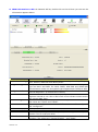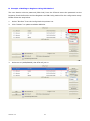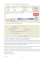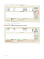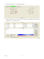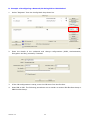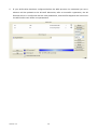
1
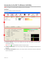
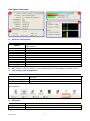
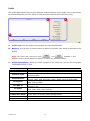
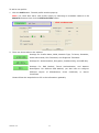
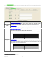
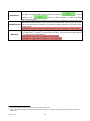
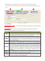
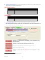
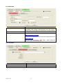
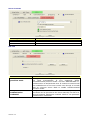
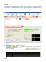
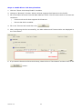
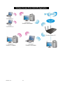
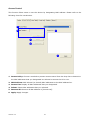
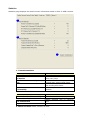
802.11n Long-Range
USB WiFi Antenna
User Manual
Version: 2.0
Version: 2.0
iii
TABLE OF CONTENTS
OVERVIEW ..........................................................1
UNPACKING INFORMATION ................................................................................................. 1
INTRODUCTION TO THE WiFi King WIRELESS USB ADAPTER .............................................. 1
KEY FEATURES ............................................................................................................... . 2
INSTALLATION GUIDE ........................................2
SOFTWARE INSTALLATION ................................................................................................. 2
MANAGEMENT GUIDE.........................................5
MAKING A BASIC NETWORK CONNECTION .......................................................................... 5
Select a configuration tool .......................................................................................... 5
To connect with Microsoft Zero Configuration tool...................................................... 5
To connect with 802.11n Wireless LAN Utility ............................................................ 7
INTRODUCTION TO THE 802.11N WIRELESS LAN UTILITY .................................................... 8
Interfaces................................................................................................................... . 8
Link Status Information ............................................................................................... 9
Profile ...................................................................................................................... . 10
Network ................................................................................................................... . 19
Advanced................................................................................................................. . 20
Statistics .................................................................................................................. . 21
WMM ....................................................................................................................... . 22
WPS ........................................................................................................................ . 24
CCX ......................................................................................................................... . 35
Radio On/Off............................................................................................................ . 35
AP MODE MANAGEMENT GUIDE FOR WINDOWS 2000/XP/VISTA ......................................... 36
Config ...................................................................................................................... . 38
Security Setting ....................................................................................................... . 40
Access Control ........................................................................................................ . 41
MAC Table............................................................................................................... . 42
Event Log ................................................................................................................ . 43
Statistics .................................................................................................................. . 44
Version: 2.0
iii
Overview
Thank you for purchasing this product. Read this chapter to learn about your Range Master WiFi
King 802.11n Wireless USB Adapter.
Unpacking Information
Before getting started, please verify that your package includes the following items:
1.
2.
3.
WiFi King Wireless USB Adapter.
Outdoor Omnidirectional Antenna.
Utility/Manual CD.
Introduction to the WiFi King Wireless USB Adapter
The WiFi King Wireless USB adapter is an IEEE 802.11n wireless 150 Mbps wireless adapter
which is also compatible with IEEE 802.11b/g and IEEE 802.11a/b/g wireless devices at
11/54 Mbps. You can configure this adapter with ad-hoc mode to connect to other 2.4GHz
wireless computers or in infrastructure mode to connect to a wireless AP or router for accessing
the internet. This adapter includes a convenient utility for scanning available networks and
saving preferred networks that users usually connected with. Security encryption can also be
configured by this utility.
Version: 2.0
1
Key Features
y
Complies with IEEE 802.11n wireless standards
y
Supports
wireless
data
encryption
64/128-bit WEP, WPA, WPA2, TKIP, AES
with
y
2.4GHz frequency band, MIMO
y
Supports QoS: WMM, WMM-PS
y
Complies with USB 2.0
y
Supports multiple BSSID
y
High speed transfer data rate up to 150 Mbps
y
y
Supports auto-installation
Supports driver for Windows 2000, XP 32/64,
Vista 32/64, Windows 7, Linux (2.4.x/2.6.x), and
Mac (10.3.x/10.4.x/10.5.x/10.6.x) Power PC &
PC
Installation Guide
Software Installation
Note:
y
For
Linux
or
Mac
driver
installation
guide,
please
refer
to
the
instruction
in
/Driver/Linux/README or /Driver/Mac/README in the CD-Rom.
y The screenshots will vary slightly depending on the version of Windows but the procedures
and screens are similar.
1.
The system finds the newly installed device automatically. Click Cancel to close this window.
2. Insert the CD-Rom that came with this product to your CD-Rom drive. The menu window pops
up automatically. Please click the Driver button of this product.
Note: If the CD-Rom fails to auto-run, please click on My Computer > your CD-Rom drive
> (folder of this product) > Driver then double-click the Setup icon to start this menu.
Version: 2.0
2
3.
Select if you are going to install the driver and wireless utility; or install the driver only.
4.
Select if you are going to configure your wireless network with this device or with Microsoft
Zero Configuration tool.
Note: This can be changed after installing this software.
Version: 2.0
3
5.
Click the Install button to start installing.
6.
Click the Finish button to complete installation.
Version: 2.0
4
Management Guide
Read this chapter to understand the management interface of the device and
how to manage the device.
Making a Basic Network Connection
Select a configuration tool
In the following instructions for making a network connection, we use the utility we provide to
configure your wireless network settings.
Note: You could use either the software we provide or Microsoft Zero Configuration tool to
configure this adapter. To switch between the two configuration tools, please right click on the…..
icon on system tray to select.
To connect with Microsoft Zero Configuration tool
After specifying the Microsoft Zero Configuration tool to configure your wireless network, right
click on the
icon on system tray. Select View Available Wireless Networks to specify your
wireless network.
Version: 2.0
5
The tool shows the available wireless networks. Select the network you want to connect to. To
connect to a wireless network with more security settings, please click Change advanced
settings and configure to be compatible with your wireless network security settings.
Version: 2.0
6
To connect with 802.11n Wireless LAN Utility
We provide this utility for users to connect to a wireless network easily. It provides more
information and configuration for this adapter. As default, the utility is started automatically upon
starting your computer and connects to a connectable wireless network with best signal strength
icon in the system ray and select Launch
and with no security setting. Right click on the
Config utilities if the utility does not start. Please refer to the following chapters to get
information regarding to the functions of this utility.
Version: 2.0
7
Introduction to the 802.11n Wireless LAN Utility
Note: The Utility in Linux and Mac are different from the following.
Interfaces
This utility basically consists of three parts:
1
2
3
1. Function Buttons: on top of the window. You can click each button to access each
configuration window.
Note: Click
to enable/disable wireless connection status.
2. Configuration Column: Center of the Utility window. Make your changes for each function in
this part.
3. Link Status Information: bottom of the utility window. Shows the connection status and
system information.
Version: 2.0
8
Link Status Information
A
C
D
B
A.
Network Information:
Items
Status
Extra Info
Channel
Authentication
Encryption
Network Type
IP Address
Sub Mask
Default Gateway
Link Speed
Throughput
Information
Show the connecting status. Also shows the SSID while connecting to a
valid network.
Display link status in use.
Display current channel in use.
Authentication mode in use.
Encryption type in use.
Network type in use.
IP address of current connection.
Subnet mask of current connection.
Default gateway of current connection.
Show current transmit rate and receive rate.
Display transmit and receive throughput in Mbps.
B.
HT: Display current HT status in use, containing BW, GI, MCS, SNR0, and SNR1 value.
C.
Link Quality and Strength Bar:
Items
Link Quality
Signal Strength 1
Noise Strength
Information
Display connection quality based on signal strength and TX/RX packet
error rate.
Receive signal strength 1.
Display noise signal strength.
User can choose to display Signal and Noise Strength as percentage or dBm format by mark the
dBm checkbox.
D.
Statistics:
Items
Link Speed
Throughput
Version: 2.0
Information
Show current transmit rate and receive rate.
Display transmit and receive throughput in Mbps.
9
Profile
The profile page allows users to save different wireless settings, which helps users to get access
to wireless networks at home, office or other wireless network environments quickly.
A
C
B
A.
Profile List: The list shows all the profiles you have added before.
B.
Buttons: You can click on these buttons to add a new profile, edit, delete or activate an old
profile.
Note: For Vista user, there are extra
and
buttons in this
feature. Click on these buttons to import or export the selected profile.
C.
Profile Information: While you select a profile in the profile list, you can see the profile
information shows on here.
Items
Profile Name
SSID
Information
The name of the selected profile.
The SSID of the wireless system.
Shows Infrastructure / Ad-hoc to indicate the network type of the
Network Type
selected profile.
Shows the authentication mode in use. There are total 8 modes: Open,
Authentication
Shared, LEAP, WPA, WPA-PSK, WPA2, WPA2-PSK and WPA-NONE.
Shows the encryption mode in use. There are total 4 modes: None,
Encryption
WEP, TKIP and AES.
Shows Yes/No to indicate whether the selected profile use the 802.1x
Use 802.1x
feature or not.
Shows the transmit power in use. There are total 7 types: Auto, 100%,
Tx Power
75%, 50%, 25%, 10% and Low.
Channel
Shows the channel in use (1~14) for Ad-Hoc mode.
Shows the power save mode in use. Two selections: CAM (Constantly
Power Save Mode
Awake Mode) and PSM (Power Saving Mode).
RTS Threshold
Shows the RTS threshold value in use.
Fragment Threshold Shows the fragment threshold in use.
Version: 2.0
10
To add a new profile:
1. Click the Add button. The add profile window pops up.
Note: you could also add a new profile quickly by selecting an available network in the
Network function then click the Add to Profile button.
← Click on these tabs
2. There are three tabs on the window:
Settings for: Profile Name, SSID, Network Type, Tx Power, Preamble,
Power Save Mode, RTS Threshold, and Fragment Threshold.
Settings for: Authentication, Encryption, Preshared Key, and WEP Key.
Settings for:
EAP Method, Tunnel
Authentication,
and
Session
Resumption. For different EAP Method, you also have to configure
different
require
of
ID/Password,
Client
Certificate.
Please follow the steps below to fill in the information gradually.
Version: 2.0
11
Certificate,
or
Server
3. In
section, fill in information for this profile:
Items
Profile Name
Information
Choose a name for this profile, or use default name defined by system.
Fill in the intended SSID name or use the drop list to select from
SSID
available APs.
There are two types, infrastructure and 802.11 Ad-hoc modes. Under
Ad-hoc mode, you could also choose the preamble type; the available
Network Type
preamble type includes auto and long. In addition to that, the channel
field will be available for setup in Ad-hoc mode.
Transmit power, the amount of power used by a radio transceiver to
Tx Power
send the signal out.
Two selections: Auto, and Long Preamble. This can only be set up in
Preamble
Ad –hoc mode.
Channel
Channel in use for Ad-Hoc mode.
Choose from CAM (Constantly Awake Mode) or PSM (Power Saving
Power Save Mode
Mode).
For adjusting the RTS threshold number by sliding the bar or key in the
RTS Threshold
value directly. The default value is 2347.
Adjust the Fragment threshold number by sliding the bar or key in the
Fragment Threshold
value directly. The default value is 2346.
Version: 2.0
12
4. In
section, select an encryption type and fill in the corresponding wireless
network information:
Items
Information
For Windows 2000 User
There are 7 types supported: Open, Shared, LEAP, WPA, WPA-PSK, WPA2,
Authentication WPA2-PSK, and WPA-NONE1. Please select a type from the drop down list.
Type
For Vista User
There are 7 types supported: Open, Shared, WPA, WPA-PSK, WPA2, WPA2-PSK,
and CCKM. Please select a type from the drop down list.
For Windows 2000 User
There are 4 types supported: None, WEP, TKIP and AES.
The available encryption selection will differ from the authentication type you
have chosen, the result is shown below:
Authentication
Open
Shared
LEAP
WPA/WPA2/WPA-PSK
WPA2-PSK/WPA-NONE
Encryption
Type
For Vista User
There are 6 types supported: None, WEP, TKIP, AES, TKIP (MFP) and AES (MFP).
The available encryption selection will differ from the authentication type you
have chosen, the result is shown below:
Authentication
Open
Shared
WPA/ WPA-PSK/ WPA2-PSK
WPA2
CCKM
1
WPA-NONE is only available in Ad-hoc mode.
Version: 2.0
Available Encryption Selection
NONE, WEP
WEP
(no selection)
TKIP, AES
13
Available Encryption Selection
NONE, WEP
WEP
TKIP, AES
TKIP, AES, TKIP(MFP), AES(MFP)
WEP, TKIP, AES
This checkbox appears while the environment is set to an Open authentication
Use 802.1x
with WEP encryption. Mark the checkbox to make the
section
available. The
section is also available in WPA and WPA2
authentication types.
This is the shared secret between AP and STA. For WPA-PSK, WPA2-PSK and
WPA-NONE authentication mode, this field must be filled with characters longer
Preshared Key than 8 and less than 32 lengths. The following dialog appears if you have input
invalid values.
WEP Key
1
2
Only available when using WEP encryption algorithm. The key must match AP's
key. Select Hex1 or ASCII2 to setup the key value. The following dialog appears
if you have input invalid values.
Hexadecimal digits consist of the numbers 0-9 and the letters A-F.
ASCII (American Standard Code for Information Interchange) is a code for representing English letters as numbers
from 0-127.
Version: 2.0
14
5. Specify the 802.1x information if you are using the 802.1X certification method.
Users that do not use this function or connect to an open-wireless network please skip this
part.
A
A.
B
C
EAP Method:
For Windows 2000 User: There are total 5 modes: PEAP, TLS/Smart Card, TTLS, EAP-FAST, and
MD5-Challenge.
For Vista User: There are total 4 modes: PEAP, TLS/Smart Card, EAP-FAST, and LEAP.
Please select an EAP method from the drop down list.
Items
Information
Protect Extensible Authentication Protocol. PEAP transport securely authenticates
data by using tunneling between PEAP clients and an authentication server. PEAP can
PEAP
authenticate wireless LAN clients using only server-side certificates, thus simplifying
the implementation and administration of a secure wireless LAN.
Transport Layer Security. Provides for certificate-based and mutual authentication of
the client and the network. It relies on client-side and server-side certificates to
TLS/Smart
perform authentication and can be used to dynamically generate user-based and
Card
session-based WEP keys to secure subsequent communications between the WLAN
client and the access point.
Tunneled Transport Layer Security. This security method provides for
TTLS
certificate-based, mutual authentication of the client and network through an
encrypted channel. Unlike EAP-TLS, EAP-TTLS requires only server-side certificates.
Flexible Authentication via Secure Tunneling. It was developed by Cisco. Instead of
using a certificate, mutual authentication is achieved by means of a PAC (Protected
Access Credential) which can be managed dynamically by the authentication server.
The PAC can be supplied (distributed one time) to the client either manually or
EAP-FAST
automatically. Manually, it is delivered to the client via disk or a secured network
distribution method. Automatically, it is supplied as an in-band, over the air,
distribution. For tunnel authentication, only support "Generic Token Card"
authentication.
Message Digest Challenge. Challenge is an EAP authentication type that provides
MD5base-level EAP support. It provides for only one-way authentication - there is no
Challenge
mutual authentication of wireless client and the network.
Light Extensible Authentication Protocol is an EAP authentication type used primarily
LEAP
by Cisco Aironet WLANs. It encrypts data transmissions using dynamically generated
WEP keys, and supports mutual authentication.
Version: 2.0
15
B.
Tunnel Authentication: The tunnel authentication will differ from the EAP method you
have chosen, the result is shown below:
For Windows 2000 User:
EAP Method
PEAP
TLS/Smart Card
TTLS
EAP-FAST
MD5-Challenge
Tunnel Authentication
EAP-MSCHAP v2 , EAP-TLS/Smart Card, Generic Token Card
(no selection)
CHP, MS-CHAP, MS-CHAP-V2, PAP, EAP-MD5
Generic Token Card
(no selection)
For Vista User:
EAP Method
PEAP
TLS/Smart Card
EAP-FAST
LEAP
C.
Tunnel Authentication
EAP-MSCHAP v2 , EAP-TLS/Smart Card, Generic Token Card
(no selection)
(no selection)
(no selection)
Session Resumption: Mark to enable this function or unmark it to disable.
After doing the above settings, please click on the tabs below. There are several tabs on the
window, please fill in the information gradually.
← Click on these tabs
Settings for: Authentication ID/Password, Tunnel ID/Password and
Password Mode1.
Settings for using the Client Certificate function or not.
Settings for using the Server Certificate function or not.
Setting for EAP-FAST method.
Settings for Single Sign On. Note: This tab only appears in Vista
system.
1
Password mode is only available in EAP-FAST method.
Version: 2.0
16
ID \ PASSWORD
Items
Authentication ID / Password
Tunnel ID / Password
Password Mode
Information
The identity, password and domain name for server. Only
"EAP-FAST" and "LEAP" authentication can be keyed in
domain name. Blank space can be keyed in domain name.
Identity and Password for server.
Select the power save mode.
For Windows 2000 User
There are two selections: Soft Token and Static Password.
For Vista User
There are four selections: Soft Token, Static Password,
Windows Logon and Prompt User.
Client Certificate
Items
Use Client certificate
Use my smart card
Version: 2.0
Information
Client certificate for server authentication.
Client certificate for server authentication.
17
Server Certificate
Items
Use Certificate chain
Allow intimidate certificates
Server name
Information
Mark the checkbox to enable using certification chain.
Mark to allow intimidates certification.
Enter an authentication sever root.
EAP Fast
Items
Allow unauthenticated
provision mode
Use protected
authentication
credential
Version: 2.0
Information
During the PAC can be provisioned (distributed one time) to
the client automatically. It only supported "Allow
unauthenticated provision mode" and use "EAP-MSCHAP v2"
authentication to authenticate now. It causes to continue with
the establishment of the inner tunnel even though it is made
with an unknown server. Mark to enable unauthenticated
provision mode.
Use protected authentication credential: Using PAC, the
certificate can be provided to the client manually via disk or a
secured network distribution method. Mark to use protected
authentication credential.
18
Network
This network lists the available wireless networks. The utility connects to a wireless network with
the best signal strength automatically. You can change the connecting network by clicking on
the network name and click the Connect button. To see detail information of each network,
please double click on each item to pop up the information window.
A
B
C
A.
Sorted by: Click each button to sort the listing networks by SSID, channel and Signal
strength.
B.
Show dBm: Mark the checkbox to show the
signal and noise strength in dBm, unmark to
show in percentage.
C.
Buttons: You can click on these buttons to add a
new profile, edit, delete or activate an old profile.
Items
Rescan
Connect
Add to Profile
Version: 2.0
Information
To rescan available wireless networks.
To connect to a designated network.
To add a network to profile after selecting a network.
19
Advanced
This page provides advanced configurations to this adapter. Please refer to the following chart for
definitions of each item.
Items
Wireless mode
Enable TX Burst
Enable TCP Window Size
Fast Roaming at
dBm
Show Authentication Status
Dialog
Select Your Country Region
Code
Information
Select wireless mode. 2.4G/5.8G is supported.
Select to enable connecting to a TX Burst supported device.
Mark the checkbox to enable TCP window size, which help
enhance throughput.
Mark the checkbox to enable fast roaming. Specify the
transmit power for fast roaming.
Mark the checkbox to show “Authentication Status Dialog”
while connecting to an AP with authentication.
Authentication Status Dialog displays the process about
802.1 x authentications.
Eight countries to choose. Channel list:
1 ~ 11 channels (North America)
1 ~ 13 channels (General Europe)
1 ~ 14 channels (Japan)
IEEE802.11a
4 Channels (Japan)
Enable CCX (Cisco Compatible
extensions)
Turn on CCKM
Enable Radio Measurements
Non-Serving Channel
Measurements limit
19 Channels (Europe)
13 Channels (USA)
Select to enable CCX. This function can only be applied
when connecting to a Cisco compatible device.
Mark to enable CCKM.
Mark to enable channel measurement every 0~2000
milliseconds.
Mark to revise the channel measurement.
Note: For Vista user, click on the CCX button to do more configuration. Please refer to CCX for
more information.
Version: 2.0
20
Statistics
Statistics page displays the detail counter information based on 802.11 MIB counters. This page
translates the MIB counters into a format easier for user to understand.
Items
Frames Transmitted Successfully
Frames
Retransmitted
Successfully
Frames Fail To Receive ACK After
All Retries
RTS Frames Successfully Receive
CTS
RTS Frames Fail To Receive CTS
Reset Counter
Information
Frames successfully sent.
Successfully retransmitted frames numbers.
Frames failed transmit after hitting retry limit.
Successfully receive CTS after sending RTS frame.
Failed to receive CTS after sending RTS.
Reset counters to zero.
Items
Frames Received Successfully
Frames Received With CRC Error
Frames Dropped Due To Out-of-Resource
Duplicate Frames Received
Reset Counter
Information
Frames received successfully.
Frames received with CRC error.
Frames dropped due to resource issue.
Duplicate received frames.
Reset counters to zero.
Version: 2.0
21
WMM
This page allows users to activate the WMM function for this device. Please note that this function
only works while connecting to a WMM compatible device.
Items
WMM Enable
WMM - Power Save Enable
Direct Link Setup Enable
MAC Address
Timeout Value
Apply / Tear Down
Version: 2.0
Information
Enable Wi-Fi Multi-Media.
Enable WMM Power Save. Please enable WMM before
configuring this function.
Enable DLS (Direct Link Setup). Please enable WMM before
configuring this function.
Fill in the blanks of Direct Link with MAC Address of STA.
Time of automatically disconnect after some seconds. The
value is integer. The integer must be between 0~65535. It
represents that it always connects if the value is zero.
Default value of Timeout Value is 60 seconds.
After fill in the "MAC Address" and "Timeout Value", click
"Apply" button to save your configuration. The result will
appear in the following "DLS Status" blanks. To remove
the configuration, please select the configuration in the
blanks and then click "Tear Down" button.
22
Steps to enable Direct Link Setup function:
1. Click the "Direct Link Setup Enable" checkbox.
2. Change to "Network" function. Add an AP that supports DLS features to the Profile.
3. Fill in the blanks of Direct Link with MAC Address of STA. The STA must conform to these two
conditions:
y
Connect with an AP that supports DLS features.
y
Ensure that DLS is enabled
4. Fill in the Timeout Value and then click
.
5. After configuring the DLS successfully, the MAC address and Timeout Value are displayed in
the "DLS Status".
DLS Status
6. If you want to disconnect Direct Link Setup, select the list in “DLS Status” and then click on the
button.
Version: 2.0
23
WPS
The primary goal of Wi-Fi Protected Setup (Wi-Fi Simple Configuration) is to simplify the security
setup and management of Wi-Fi networks. This adapter supports the configuration setup using
PIN configuration method or PBC configuration method through an internal or external Registrar.
1
3
4
5
2
6
7
8
13
15
16
14
9
18
10
19
17
11
12
Items
1. WPS AP List
2.
3.
4.
5.
6.
7.
8.
9.
10.
11.
12.
13.
14.
15.
16.
17.
18.
19.
Information
Display the information of surrounding APs with WPS IE from last scan
result. List information includes SSID, BSSID, Channel, ID (Device
Password ID), and Security-Enabled.
WPS
Profile Display all of credentials got from the Registrar. List information includes
List
SSID, MAC Address, Authentication and Encryption Type. If STA Enrollee,
credentials are created as soon as each WPS success. If STA Registrar,
Utility creates a new credential with WPA2-PSK/AES/64Hex-Key and
doesn't change until next switching to STA Registrar.
Rescan
Click to rescan the wireless networks.
Information Display the information about WPS IE on the selected network. List
information includes Authentication Type, Encryption Type, Config
Methods, Device Password ID, Selected Registrar, State, Version, AP Setup
Locked, UUID-E and RF Bands.
Pin Code
8-digit numbers. It is required to enter PIN Code into Registrar using PIN
method. Each Network card has only one PIN Code of Enrollee. Click on the
Renew button to renew the PIN code.
Config Mode Enrollee or an external Registrar.
Detail
Information about Security and Key in the credential.
Connect
Command to connect to the selected network inside credentials.
Rotate
Command to connect to the next network inside credentials.
Stop WPS action and disconnect this active link. And then select the last
Disconnect
profile at the Profile Page of Utility if exists. If there is an empty profile
page, the driver will select any non-security AP.
Export Profile Click the "Export Profile" button will export the WPS profile.
Delete an existing credential. And then select the next credential if exist. If
Delete
there is an empty credential, the driver will select any non-security AP.
PIN
Start to add to Registrar using PIN configuration method.
PBC
Start to add to AP using PBC configuration method.
Send the association request with WPS IE during WPS setup. It is optional
WPS
associate IE for STA.
WPS probe IE Send the probe request with WPS IE during WPS setup. It is optional for
STA.
Auto
Select the AP automatically.
Progress Bar Display rate of progress from Start to Connected status.
Status Bar
Display currently WPS Status.
Version: 2.0
24
The following description divides into four parts:
A. WPS Information on AP
B. Example of Adding to Registrar Using PIN Method
C. Example of Adding to Registrar Using PIN Method
D. Example of Configuring a Network/AP Using PIN or PBC Method
Version: 2.0
25
A. WPS Information on AP: On Network AP list, double click on the AP then you can see the
information appears below.
Items
Information
Authentication Type There are three authentication modes supported by this utility. They are
open, Shared, WPA-PSK and WPA system.
For open and shared authentication mode, the selection of encryption
Encryption Type
type are None and WEP. For WPA, WPA2, WPA-PSK and WPA2-PSK
authentication mode, the encryption type supports both TKIP and AES.
Correspond to the methods the AP supports as an Enrollee for adding
Config Methods
external Registrars. (a bitwise OR of values)
Device Password ID Indicates the method or identifies the specific password that the selected
Registrar intends to use. APs in PBC mode must indicate 0x0004 within
two-minute Walk Time.
Selected Registrar Indicates if the user has recently activated a Registrar to add an Enrollee.
The values are "TRUE" and "FALSE".
The current configuration state on AP. The values are "Unconfigured"
State
and "Configured".
Version
AP Setup Locked
UUID-E
RF Bands
Version: 2.0
WPS specified version.
Indicates if the AP has entered a setup locked state.
The universally unique identifier (UUID) element generated by the
Enrollee. This is a 16 byte value.
Indicates all the RF bands available on the AP. A dual-band AP must
provide it. The values are "2.4GHz/5.8GHz" and "5GHz".
26
B. Example of Adding to Registrar Using PIN Method
The user obtains a device password (PIN Code) from the STA and enters the password into the
Registrar. Both the Enrollee and the Registrar use PIN Config method for the configuration setup.
Please follow the step below.
1.
Select "Enrollee" from the Config Mode drop-down list.
2.
Click "Rescan" to update available WPS APs.
3.
Select an AP (SSID/BSSID) that STA will join to.
Version: 2.0
27
4.
Click "PIN" to enter the PIN.
5.
Enter the PIN Code of the STA into the Registrar when prompted by the Registrar.
Note:
y
Allow of an exchange between Step 4 and Step 5.
y
If you use Microsoft Window Connection Now as an External Registrar, you must start
PIN connection at STA first. After that, search out your WPS Device name and MAC
address at Microsoft Registrar. Add a new device and enter PIN Code of STA at Microsoft
Registrar when prompted.
6.
The result should appear as the image below.
Version: 2.0
28
7.
Configure one or more credentials. Then connect successfully.
8.
Click "Detail." You can see the figure below.
C. Example of Adding to the Registrar Using the PBC Method
The PBC method requires the user to press a PBC button on both the Enrollee and the Registrar
within a two-minute interval called the Walk Time. If there is only one Registrar in PBC mode, the
PBC mode selected is obtained from ID 0x0004, and is found after a complete scan. The Enrollee
can then immediately begin running the Registration Protocol.
If the Enrollee discovers more than one Registrar in PBC mode, it MUST abort its connection
attempt at this scan and continue searching until the two-minute timeout.
Note: Before you press PBC on STA and candidate AP. Make sure all APs aren't PBC mode or APs
using PBC mode have left their Walk Time. The user can configure WPS profiles with either PIN
method or PBC method.
Please follow the steps below.
Version: 2.0
29
1.
Select "Enrollee" from the Config Mode drop-down list.
2.
Click PBC to start the PBC connection.
3.
Push the PBC on AP.
Note: Allow time for an exchange between Step 2 and Step 3.
Version: 2.0
30
4.
The progress bar as shown in the figure below indicates that scanning progress.
5.
When one AP is found, join it.
Version: 2.0
31
6.
Check WPS Information on the available WPS APs.
7.
Configure and receive one or more credential(s).Then connect successfully. The result will be
displayed as it is in the figure below.
Version: 2.0
32
D. Example of Configuring a Network/AP Using PIN or PBC Method
1.
Select "Registrar" from the Config Mode drop-down list.
2.
Enter the details of the credential and change configurations (SSID, Authentication,
Encryption and Key) manually if needed.
3.
If the PIN configuration is setup, enter the PIN sent from the Enrollee.
4.
Start PIN or PBC. The following procedures are as similar as section PIN Enrollee Setup or
PBC Enrollee Setup.
Version: 2.0
33
5.
If your AP Enrollee has been configured before the WPS process, the credential you set in
advance will be updated to the AP itself. Otherwise, after a successful registration, the AP
Enrollee will be re-configured with the new parameters, and the STA Registrar will connect to
the AP Enrollee with these new parameters.
Version: 2.0
34
CCX
This page is available for Vista user only. It provides CCX configurations to this adapter. Please
refer to the following chart for definitions of each item.
Items
Enable CCX (Cisco Compatible
extensions)
Turn on CCKM
Enable Radio Measurements
Non-Serving Channel
Measurements limit
Network EAP
Enable RF Roaming
Enable CAC (Tolerance)
CAC
Diagnosis
Information
Select to enable CCX. This function can only be applied
when connecting to a Cisco compatible device.
Mark to enable CCKM.
Mark to enable channel measurement every 0~2000
milliseconds.
Mark to revise the channel measurement.
Enable the NetwrokEAP authentication algorithm.
Enable RF roaming function
Enable the call admission control
There are four selections: ADDTS (Directly send TS), DELTS,
and RESET. Select an item from the drop down list and then
click on the
button.
Select a profile which the user wants to diagnose, and then
click on the Diagnose button to perform the
test.
Radio On/Off
Click on the button to enable/disable wireless connection status.
Connected:
Disconnected:
Version: 2.0
35
AP mode management guide for Windows 2000/XP/Vista
If you wish to share the Internet access with the wireless stations in your environment, you can
configure this wireless adapter as a software access point (Soft AP). In this mode, this wireless
adapter becomes the wireless access point that provides local area network and Internet access
for your wireless stations.
To use this adapter as an access point, please right click the
icon
on
system
tray and
select Switch to AP mode. Please refer to the following introduction and information about this
AP-mode utility.
Note: In windows XP, it provides WPA support at hotfix Q815485. However; you have to make
sure that hotfix Q815485 (require XP SP1 installed) has been installed in your system before you
can start using WPA features. You can check the installation of hotfix in add/remove software
page under control panel.
Version: 2.0
36
Software Access Point (Soft AP) Application
Version: 2.0
37
Config
This page provides overall configuration to this adapter. Please find the following items for
identification to each field.
1
7
2
9
8
3
10
11
12
4
5
6
13
14
15
1. SSID: AP name of user type. User also can select [Use Mac Address] to display it.
2. Wireless Mode: Select wireless mode. Only 2.4G is supported.
Version: 2.0
38
3. Country Region Code: eight countries to choose. Country channel list:
Classification
Range
0: FCC (Canada)
CH1
~ CH11
1: ETSI
CH1
~ CH13
2: SPAIN
CH10 ~ CH11
3: FRANCE
CH10 ~ CH13
4: MKK
CH14 ~ CH14
5: MKKI (TELEC)
CH1
~ CH14
6: ISRAEL
CH3
~ CH9
7: ISRAEL
CH5
~ CH13
Note: Country Region code is not support for Vista.
4. Beacon (ms): The time between two beacons. System default is 100 ms.
5. TX Power: Manually force the AP transmits power. System default is 100%.
6. Idle Time: Manually force the Idle Time using selected value. Default is 300.
7. Channel: Manually force the AP using the channel. System default is channel 1.
8. Use Mac Address: Use MAC address of used wireless card to be AP name. System default is
APX (X is last number of Mac Address).
9. Security Setting: Authentication mode and encryption algorithm used within the AP. System
default is no authentication and encryption.
10. No forwarding among wireless clients: If there is no beacon among the wireless clients,
they can’t share information with each other.
11. Hide SSID: Prevent this AP from recognized in wireless network. This is disabled as default.
12. Allow BW40 MHz: Allow BW40 MHz capability.
13. Default: Use system default value.
14. Cancel: Cancel the above changes.
15. Apply: Apply the above changes.
Version: 2.0
39
Security Setting
This page pops up after clicking the Security Setting button. Please follow the instructions
below:
1
2
3
4
5
1. Authentication Type: Select to be open, shared, WPA-PSK, WPA2-PSK, or WPA
PSK/WPA2-PSK system.
2. Encryption Type: Select an encryption type from the drop list.
3. WPA Pre-shared Key: A shared string between AP and STA. For WPA-PSK
authentication mode, this field must be filled with character longer than 8 and less
than 32 lengths.
4. Group Rekey Interval: Only valid when using WPA-PSK encryption algorithm.
The key will change compliance with seconds or beacon that user set.
5. WEP Key: Only valid when using WEP encryption algorithm. The key must match
the key on AP. There are several formats to enter the keys.
a. Hexadecimal (40bits): 10 Hex characters.
b. Hexadecimal (128bits): 32Hex characters.
c. ASCII (40bits): 5 ASCII characters.
d. ASCII (128bits): 13 ASCII characters.
Version: 2.0
40
Access Control
This function filters users to use this device by designating MAC address. Please refer to the
following chart for introduction.
1
2
3
4
5
6
1. Access Policy: Choose a method to process access control from the drop list to determine
the MAC addresses that you designated are allowed to access the AP or not.
2. MAC Address: Add allowed (or denied) MAC addresses to the MAC address list.
3. Access List: Display all Mac Addresses that you designated.
4. Delete: Delete Mac addresses that you selected.
5. Remove All: Remove all Mac address in [Access List].
6. Apply: Apply changes.
Version: 2.0
41
MAC Table
This page displays the station detail information of current connection.
Items
MAC Address
AID
Power Saving
Mode
Status
Version: 2.0
Information
The station MAC address of current connection.
Raise value by current connection.
Check if the connected station supports power
saving.
The connection status.
42
Event Log
Record Soft AP all event time and message.
Items
Event Time (yy/mm/dd-hh:mm:ss)
Message
Version: 2.0
43
Information
Record event time.
All event messages.
Statistics
Statistics page displays the detail counter information based on 802.11 MIB counters.
1
2
3
1. Transmit Statistics
Items
Frames Transmitted Successfully
Frames Fail To Receive ACK After
All Retries
RTS Frames Successfully Receive
CTS
RTS Frames Fail To Receive CTS
Frames Retransmitted
Successfully
Information
Frames that successfully sent.
Frames that failed to transmit after
hitting retry limit.
Counts of CTS that successfully
received after sending RTS frame.
Counts of CTS that fail to be received
after sending RTS frame.
Successfully retransmitted frames
numbers.
2. Receive Statistics
Items
Frames Received Successfully
Frames Received With CRC Error
Frames Dropped Due To
Out-of-Resource
Duplicate Frames Received
Information
Frames received successfully.
Frames received with CRC error.
Frames dropped due to resource
issue.
Duplicate received frames.
3. Reset Counters: Reset counters to zero.
i
FCC Certifications
Federal Communication Commission Interference Statement
This equipment has been tested and found to comply with the limits for a Class B digital device,
pursuant to Part 15 of the FCC Rules. These limits are designed to provide reasonable protection
against harmful interference in a residential installation. This equipment generates, uses and can
radiate radio frequency energy and, if not installed and used in accordance with the instructions,
may cause harmful interference to radio communications. However, there is no guarantee that
interference will not occur in a particular installation. If this equipment does cause harmful
interference to radio or television reception, which can be determined by turning the equipment off
and on, the user is encouraged to try to correct the interference by one of the following measures:
-Reorient or relocate the receiving antenna.
-Increase the separation between the equipment and receiver.
-Connect the equipment into an outlet on a circuit different from that to which the receiver is
connected.
-Consult the dealer or an experienced radio/TV technician for help.
This device complies with Part 15 of the FCC Rules. Operation is subject to the following two
conditions: (1) This device may not cause harmful interference, and (2) this device must accept any
interference received, including interference that may cause undesired operation.
FCC Caution: Any changes or modifications not expressly approved by the party responsible for
compliance could void the user's authority to operate this equipment.
IMPORTANT NOTE:
FCC Radiation Exposure Statement:
This equipment complies with FCC radiation exposure limits set forth for an uncontrolled
environment. This equipment should be installed and operated with minimum distance 20cm
between the radiator & your body.
This transmitter must not be co-located or operating in conjunction with any other antenna or
transmitter.
i
CE Mark Warning
This equipment complies with the requirements relating to electromagnetic compatibility, EN
55022
Class B for ITE, the essential protection requirement of Council Directive 89/336/EEC
on the approximation of the laws of the Member States relating to electromagnetic
compatibility.
Company has an on-going policy of upgrading its products and it may be possible that
information in this document is not up-to-date. Please check with your local distributors for
the latest information. No part of this document can be copied or reproduced in any form
without written consent from the company.
Trademarks:
All trade names and trademarks are the properties of their respective
companies. Copyright © 2009-2014, All Rights Reserved.
Version: 2.0
ii