1
User information
06/2008 Ü
999759002
Method statement
GB
Doka heavy-duty
supporting system SL-1
9759-254-01
The Formwork Experts
User information Doka heavy-duty supporting system SL-1
Introduction
© by Doka Industrie GmbH, A-3300 Amstetten
2
The Formwork Experts
999759002 - 06/2008 Ü
User information Doka heavy-duty supporting system SL-1
Contents
Introduction
Page
Introduction .................................................................................................. 2
Elementary safety warnings ........................................................................ 4
Eurocodes at Doka........................................................................................ 6
System description....................................................................................... 7
System overview .......................................................................................... 9
Tunnel structures built using the cut-and-cover method........................ 10
Tunnel structures built using underground construction methods ....... 11
Basic design of Heavy-duty supporting system SL-1 .............................. 12
Joints and dimensioning - System beams SL-1 ...................................... 16
Joints between System beams SL-1......................................................... 18
Bracing ........................................................................................................ 24
Tension-rod bracing ................................................................................... 25
Connecting up Top 50 components .......................................................... 30
Connecting up Spindle struts SL-1 T16 .................................................... 32
Spindle struts SL-1 T16 .............................................................................. 34
Multi-purpose walings SL-1 WU16 ........................................................... 35
Lowering the heavy-duty supporting units .............................................. 38
Repositioning using heavy-duty rollers.................................................... 40
Repositioning with the Flanged wheel SL-1............................................. 42
Hydraulic system ........................................................................................ 46
Heavy-duty props for stationary sub-structures ...................................... 48
Clamping-connections ............................................................................... 53
Examples of the system in action ............................................................. 54
General remarks ......................................................................................... 56
Doka service offerings................................................................................ 56
Component overview................................................................................. 58
999759002 - 06/2008 Ü
The Formwork Experts
3
Introduction
User information Doka heavy-duty supporting system SL-1
Elementary safety warnings
User target groups
● This User Information booklet (Method Statement) is aimed at everyone who will be working
with the Doka product or system it describes. It
contains information on how to set up this system, and on correct, compliant utilisation of the
system.
● All persons working with the product described
herein must be familiar with the contents of this
manual and with all the safety instructions it contains.
● Persons who are incapable of reading and understanding this booklet, or who can do so only with
difficulty, must be instructed and trained by the
customer.
● The customer is to ensure that the information
materials provided by Doka (e.g. User Information booklets, Instructions for Assembly and Use,
Operating Instruction manuals, plans etc.) are
available to all users, and that they have been
made aware of them and have easy access to
them at the usage location.
Remarks on this document
● This User Information booklet can also be used
as a generic method statement or incorporated
with a site-specific method statement.
● Many of the illustrations in this booklet show the
situation during formwork assembly and are
therefore not always complete from the safety
point of view.
● Further safety instructions, especially warnings,
will be found in the individual sections of this
document!
Planning
● Provide safe workplaces for those using the
formwork (e.g. for when it is being erected/dismantled, modified or repositioned etc). It must be
possible to get to and from these workplaces via
safe access routes!
● If you are considering any deviation from the
details and instructions given in this booklet, or
any application which goes beyond those
described in the booklet, then revised static calculations must be produced for checking, as well
as supplementary assembly instructions.
4
The Formwork Experts
Rules applying during all phases of
the assignment:
● The customer must ensure that this product is
erected and dismantled, reset and generally used
for its intended purpose under the direction and
supervision of suitably skilled persons with the
authority to issue instructions.
● Doka products are ONLY to be used in accordance with the Doka User Information booklets or
other technical documentation provided by
Doka.
● The stability of all components and units must be
ensured during all phases of the construction
work!
● The functional/technical instructions, safety
warnings and loading data must all be strictly
observed and complied with. Failure to do so can
cause accidents and severe (even life-threatening) damage to health, as well as very great
material damage.
● Fire-sources are not permitted anywhere near
the formwork. Heating appliances are only
allowed if properly and expertly used, and set up
a safe distance away from the formwork.
● The work must take account of the weather conditions (e.g. risk of slippage). In extreme weather,
steps must be taken in good time to safeguard
the equipment, and the immediate vicinity of the
equipment, and to protect employees.
● All connections must be checked regularly to
ensure that they still fit properly and are functioning correctly.
It is very important to check all screw-type connections and wedge-clamped joins whenever the
construction operations require (particularly
after exceptional events such as storms), and to
tighten them if necessary.
Assembly
● The equipment/system must be inspected by the
customer before use, to ensure that it is in suitable condition. Steps must be taken to rule out the
use of any components that are damaged,
deformed, or weakened due to wear, corrosion or
rot.
● Combining our formwork systems with those of
other manufacturers could be dangerous, risking
damage to both health and property. If you
intend to combine different systems, please contact Doka for advice first.
● The assembly work must be carried out by suitably qualified employees of the client's.
999759002 - 06/2008 Ü
User information Doka heavy-duty supporting system SL-1
Introduction
Erecting the formwork
Symbols used
● Doka products and systems must be set up in
such a way that all loads acting upon them are
safely transferred!
The following symbols are used in this booklet:
Pouring
● Do not exceed the permitted fresh-concrete pressures. Excessively high pouring rates lead to
formwork overload, cause greater deflection and
risk causing breakage.
Striking the formwork
● Do not strike the formwork until the concrete has
reached sufficient strength and the person in
charge has given the order for the formwork to
be struck!
● When striking the formwork, never use the crane
to break concrete cohesion. Use suitable tools
such as timber wedges, special pry-bars or system features such as Framax stripping corners.
● When striking the formwork, do not endanger the
stability of any part of the structure, or of any
scaffolding, platforms or formwork that is still in
place!
Transporting, stacking and storing
● Observe all regulations applying to the handling
of formwork and scaffolding. In addition, the
Doka slinging means must be used - this is a
mandatory requirement.
● Remove any loose parts or fix them in place so
that they cannot be dislodged or fall free!
● All components must be stored safely, following
all the special Doka instructions given in the relevant sections of this User Information booklet!
Regulations; industrial safety
● Always observe all industrial safety regulations
and other safety rules applying to the application
and utilisation of our products in the country and/
or region in which you are operating.
☞
Important note
Failure to observe this may lead to malfunction or damage.
Caution / warning / danger
Failure to observe this may lead to material damage, and to injury to health which
may range up to the severe or even lifethreatening.
Instruction
This symbol indicates that actions need to
be taken by the user.
Sight-check
Indicates that you need to do a sightcheck to make sure that necessary actions
have been carried out.
Tip
Points out useful practical tips.
Reference
Refers to other documents and materials.
Miscellaneous
We reserve the right to make alterations in the interests of technical progress.
Unless otherwise stated, all dimensions are given
in cm.
Instruction as required by EN 13374:
● If a person or object falls against, or into, the
sideguard system and/or any of its accessories,
the sideguard component affected may only continue in use after it has been inspected and
passed by an expert.
Maintenance
● Only original Doka components may be used as
spare parts.
999759002 - 06/2008 Ü
The Formwork Experts
5
User information Doka heavy-duty supporting system SL-1
Eurocodes at Doka
In Europe, a uniform series of Standards known as
Eurocodes (EC) was developed for the construction
field by the end of 2007. These are intended to provide a uniform basis, valid throughout Europe, for
product specifications, tenders and mathematical
verification.
The EC are the world's most highly developed
Standards in the construction field.
In the Doka Group, the EC are to be used as standard from the end of 2008. They will thus supersede
Ed
Ed
Fd
Fk
γF
Design value of effect of actions
(E ... effect; d ... design)
Internal forces from action Fd
(VEd, NEd, MEd)
Design value of an action
Fd = γF · Fk
(F ... force)
Characteristic value of an action
"actual load"
(k ... characteristic)
e.g. dead weight, live load, concrete pressure, wind
Partial factor for actions
(in terms of load; F ... force)
e.g. for dead weight, live load, concrete pressure, wind
Values from EN 12812
the DIN norms as the "Doka standard" for product
design.
The widely used "Permissible stress design" (comparing the actual stresses with the permissible
stresses) has been superseded by a new safety concept in the EC.
The EC contrast the actions (loads) with the resistance (capacity). The previous safety factor in the
permissible stresses is now divided into several
partial factors. The safety level remains the same!
Rd
Rd
Design value of the resistance
(R ... resistance; d ... design)
Design capacity of cross-section
(VRd, NRd, MRd)
Rk
Rk
Timber: Rd = kmod ·
Steel: Rd =
γM
γM
Rk
Characteristic value of the resistance
e.g. moment resistance to yield stress
γM
Partial factor for a material property
(in terms of material; M...material)
e.g. for steel or timber
Values from EN 12812
kmod Modification factor (only for timber – to take
account of the moisture and the duration of
load action)
e.g. for Doka beam H20
Values as given in EN 1995-1-1 and EN 13377
Comparison of the safety concepts (example)
Permissible stress design
115.5 [kN]
Fyield
EC/DIN concept
115.5 [kN]
90<105 [kN]
n ~ 1.65
90 [kN]
Factual
A
Ed
gF = 1.5
Fpermissible
A
98013-100
60 [kN]
Rd gM = 1.1
98013-102
60<70 [kN]
Rk
Factual≤ Fpermissible
The "permissible values" communicated in
Doka documents (e.g.: Qpermissible = 70 kN) do
not correspond to the design values (e.g.:
VRd = 105 kN)!
➤ Avoid any confusion between the two!
➤ Our documents will continue to state the
permissible values.
Allowance has been made for the following
partial factors:
γF = 1.5
γM, timber = 1.3
γM, steel = 1.1
kmod = 0.9
In this way, all the design values needed in
an EC design calculation can be ascertained
from the permissible values.
E d ≤ Rd
A Load factor
6
The Formwork Experts
999759002 - 06/2008 Ü
User information Doka heavy-duty supporting system SL-1
System description
Doka heavy-duty supporting system
SL-1 - the versatile system for tunnel
construction
Areas of use
Cut-and-cover tunnel construction
The universal modular "kit" system of the Heavyduty supporting system SL-1 consists of steel girders and heavy-duty props that adapt easily and efficiently to any shape and load. All system components are available for rent.
A versatile system with high load-bearing
capacity
● small number of different parts
● quick to assemble (cuts costs)
● easy to brace using tie-rods (makes work easier
inside the HD supporting units)
● compatible with other Doka systems
● entire system can be rented (permits highly economical solutions)
Can be used wherever there are high loads to
be transferred
● cut-and-cover tunnels
● in short-term assignments on underground
(bored) tunnels
● avalanche galleries and similar areas of use
Permitted loading of up to 420 kN per strut
● permits wide drive-through access openings
● ensures the very highest safety standards
Easy to reposition using hydraulic "Chain travelling unit"
● moves the heavy-duty supporting unit to its next
location in just a few minutes
● requires only 1 man and a watchman for the
repositioning operation
● means swift, safe repositioning in every phase of
the work
The Heavy-duty supporting system SL-1 is
mostly used in conjunction with components of the Large-area formwork Top 50, or
of the Staxo and d2 load-bearing towers.
For this reason, read and follow the User
Information booklets for these systems as
well.
999759002 - 06/2008 Ü
The Formwork Experts
7
User information Doka heavy-duty supporting system SL-1
Underground tunnel construction
Underground tunnel construction under top
cover
Drive-through access openings beneath falsework
Custom constructions
In bridge-building
8
The Formwork Experts
999759002 - 06/2008 Ü
User information Doka heavy-duty supporting system SL-1
System overview
A
G
D
9759-255-01
C
F
E
B
A Joints and dimensioning – System beams SL-1 (Page 16)
B Lowering the heavy-duty supporting units (Page 38)
C Tension-rod bracing (Page 25)
D Bracing (Page 24)
E Repositioning heavy-duty supporting units (Page 40)
F Struts SL-1 (Page 48)
G Clamping connections (Page 53)
999759002 - 06/2008 Ü
The Formwork Experts
9
User information Doka heavy-duty supporting system SL-1
Tunnel structures built using the cut-and-cover method
Tunnel formwork used in cut-and-cover construction should have large influence widths, only a
small number of wall-ties, and be easy to reposition.
Required product features:
● high permitted loads
● ease of formwork operation
● minimal erection work
Operational steps after pouring
With a combination of the Lowering shoe SL-1 T16
and Spindle struts SL-1 T16, generous striking-distances can be obtained quickly, even on walls.
Waling system SL-1 T16
The special hole-grid on the Multi-purpose walings
SL-1 WU16 gives them a high degree of versatility.
They can be used with Waling connectors SL-1 to
make rentable, flexurally rigid joints in straight wall
formwork.
A
B
9759-278-02
C
A Multi-purpose waling SL-1 WU16
B Waling connector SL-1 WU16 0.75m
C Connecting pin SL-1 D32 100 with Spring cotter 6mm
Form-tie system 20.0
9759-254-02
The high load-bearing capacity of the Form-tie system 20.0 means that far fewer wall-ties are needed.
D
E
B
C
A
9759-294-01
A Top 50 element
B Tie-rod 20.0
C Super-plate 20.0 B
D Plastic tube 26mm
E Universal cone 26mm
Tie-rod 20.0mm:
Permitted capacity with safety factor of 1.6: 220 kN
Permitted capacity to DIN 18216: 150 kN
10
The Formwork Experts
Striking formwork from walls
➤ Working from the ground, take out the bottom
rows of form-ties.
➤ Take out the form-ties from the top rows of ties.
These form-tie locations can be reached from the
platforms.
➤ To take the load off the spindle struts, strike the
wedge of the lowering shoe with a hammer.
➤ Pull the Fastening pins T16 out of the telescopic
spindle struts.
➤ Retract the wall formwork by means of the
hydraulic cylinder.
Lowering the heavy-duty supporting units
➤ See "Lowering the heavy-duty supporting units"
Repositioning the heavy-duty supporting units
➤ See "Repositioning using heavy-duty rollers" or
"Repositioning using Chain travelling unit SL-1"
999759002 - 06/2008 Ü
User information Doka heavy-duty supporting system SL-1
Tunnel structures built using underground construction
methods
Particularly in the building of tunnels using underground construction methods, the formwork has to
feature large lowering distances and leave as much
space as possible for the site crew.
These special requirements are met by the combination of Multi-purpose walings SL-1 WU 16 and
Spindle struts SL-1 T16.
Required product features:
● high permitted loads, meaning
- large influence widths
- small number of parallel frame sections / waling levels
- ample space for the operators
● large lowering distance for easy cleaning
● easy-to-operate, hydraulically operated formwork
● minimal erection work
Cleaning the tunnel-crown formwork
Lowering the heavy-duty supporting units
➤ See "Lowering the heavy-duty supporting units"
Folding down the tunnel formwork
➤ Depending on the arrangement of the superstructure, it may be necessary to detach the overhead diagonal bracing of the Spindle struts SL-1
T16.
Make sure that there is enough clearance
for the diagonal bracing while it changes
position.
➤ Raise the tunnel-crown formwork max. 5 mm by
hydraulic cylinder.
E
D
Operational steps after pouring
C
Striking formwork from walls
➤ To take the load off the spindle struts, strike the
wedge of the lowering shoe with a hammer.
➤ Pull the Fastening pins T16 out of the telescopic
spindle struts.
➤ Retract the wall formwork by means of the
hydraulic cylinder.
9759-280-01
➤ Take out the ground anchors.
C Spindle strut SL-1 T16
D Special hydraulic cylinder with lowering brake valve
E Diagonal bracing
This takes the pressure off the spindle struts.
➤ Pull the Fastening pins T16 out of the telescopic
spindle struts.
➤ Lower the formwork units by hydraulic cylinder,
on alternate sides, and clean them.
B
9759-285-01
C
D
A
9759-284-01
A Ground anchor
Repositioning the heavy-duty supporting units
➤ See "Repositioning using heavy-duty rollers" or
"Repositioning using Chain travelling unit SL-1"
B Lowering shoe SL-1
C Spindle strut SL-1 T16
D Hydraulic cylinder
999759002 - 06/2008 Ü
The Formwork Experts
11
User information Doka heavy-duty supporting system SL-1
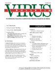
Basic design of Heavy-duty supporting system SL-1
The procedures outlined below are based on the
following basic types:
● Variant 1: Supporting frames with overhead longitudinal profiles
● Variant 2: Heavy-duty supporting unit with integral longitudinal profiles
As the Heavy-duty supporting system SL-1 is a universal modular system, it can also be combined to
make supporting constructions that differ greatly
from the two basic types described here.
➤ In these cases, you should discuss the assembly
procedure with your Doka technician.
➤ Follow the shop drawing / assembly plan exactly.
➤ Read and observe any additional documents
which may have been drawn up by Doka for the
project in question.
☞
A hard, flat, firm surface is needed!
Note:
The Tool box SL-1 contains a selection of tools specially chosen to help with assembly of this system.
A dynamometric wrench with a setting range of 150
- 200 Nm must be provided on-site.
All standardised joins are statically dimensioned
as shear / bolt-bearing joins.
Variant 1: Heavy-duty supporting
unit with overhead longitudinal profiles
➤ Position the lowering wedges (A) as per the
measurements given in the shop drawing.
Allow for the lowering distance needed for lowering the heavy-duty supporting unit.
➤ Place the longitudinal system beams (B) onto the
lowering wedges, and align them exactly.
B
9759-244-01
F
A
Attach e.g. Multi-purpose walings WS10
Top50 (F) as distance pieces.
➤ Pre-assemble the supporting frame (E) flat on the
ground.
E
9759-246-01
Warning!
Highly stressed threaded joints!
Risk of fracture if unsuitable screws are
used.
➤ When joining SL-1 system components,
ALWAYS use the appropriate Screw sets
SL-1 only.
➤ Use NEW Screw sets SL-1 every time the
equipment is re-assembled.
➤ Crane-lift the supporting frame (E) into the
upright and mount it onto the flat-placed system
beams
E
9759-243-01
To prevent the joints working loose:
➤ Lubricate all bolts and nuts with WD40
spray.
➤ Fit washers facing the head and the nut of
each bolt.
➤ Tightening torque of the nuts: 150 Nm.
Take care with high and short units!
If the first supporting frame is mounted on
the end of the flat-placed system beams, it
may topple over!
➤ Always mount the first supporting frame
a suitable distance in from the end of the
system beam.
➤ Detach the supporting frame (E) from the crane
tackle. Use a suitable service tower to reach the
slinging points.
12
The Formwork Experts
999759002 - 06/2008 Ü
User information Doka heavy-duty supporting system SL-1
9759-242-01
➤ Erect further supporting frames in the same way.
➤ Set down the overhead System beams (G) by
crane, mount them to the supporting frames, and
then detach them from the crane tackle. Provide
a safe workplace that is suitable for carrying out
this work (e.g. platforms or a platform trolley).
9759-297-01
G
9759-297-01
H
9759-241-01
➤ Mount diagonal bracing. For details, see the section headed "Tension-rod bracing".
Note:
For more information on assembly, dismantling
and the workflow, see the shop drawing / assembly
plan.
999759002 - 06/2008 Ü
The Formwork Experts
13
User information Doka heavy-duty supporting system SL-1
➤ Measure up the positions of the lowering wedges
(A) as per shop drawing.
Allow for the lowering distance needed for lowering the heavy-duty supporting unit.
➤ Pre-assemble the side supporting frames (B) ,
incl. Knee-braces SL-1 (C) , at ground level.
➤ Attach panel struts (D) to help stand the frames
upright.
➤ Mount two system beams (E) as a cross connection at the top. Provide a safe workplace that is
suitable for carrying out this work (e.g. platforms
or a platform trolley).
E
9759-238-01
Variant 2: HD supporting unit with
integral longitudinal profiles
C
B
A
D
9759-240-01
9759-239-01
➤ Crane-lift the supporting frames into the
upright, and fix the panel struts to the
ground.
➤ Secure the HD supporting units so that
they cannot topple over in either direction
(e.g. by fixing extra panel struts on the
opposite side, or anchoring each HD unit
to the foundation).
14
The Formwork Experts
G
9759-237-01
The panel struts can now be removed.
➤ Mount further system beams in the same way.
➤ Mount diagonal bracing. For details, see the section headed "Tension-rod bracing".
Note:
For more information on assembly, dismantling
and the workflow, see the shop drawing / assembly
plan.
999759002 - 06/2008 Ü
User information Doka heavy-duty supporting system SL-1
Notes
999759002 - 06/2008 Ü
The Formwork Experts
15
User information Doka heavy-duty supporting system SL-1
Joints and dimensioning - System beams SL-1
The System beams SL-1 are modular, combinable
steel girders from which universal heavy-duty supporting units can be assembled.
Standardised joints:
End-face join
Butt-strap join
Overview of variants
System beams SL-1
TR585-200-01
TR585-201-01
Beam join with stacking piece
4.00m
3.00m
1.00m
0.75m
The Offset pin SL-1 makes it easier to align
the drilled holes during assembly.
T-joint
T-joint with connecting plate
9759-201-01
16
The Formwork Experts
9759-224-01
5.00m
999759002 - 06/2008 Ü
User information Doka heavy-duty supporting system SL-1
Buckling diagram: System beam SL-1 not screwjointed
c
c
200
c
180
c
y
y
177
c
160
b
c
140
Permitted moment M [kNm]
O
a
9759-236-01
a ... 22.6 cm
b ...24.0 cm
c ... System increment-grid 50.0 cm
Technical data:
Section modulus: 1200 cm3
Moment of inertia: 14,600 cm4
Permitted internal forces: System beam SL-1 not
screw-jointed (without proof of stability - see buckling diagram for System beams SL-1)
250
P
120
Q
R
100
S
80
65
60
O
P
40
Q
R
S
z
z
20
9759-108a
0
200
y
I
G H
y
50
100
150
200
250
300
350
400
450
500
Permitted normal force N [kN]
J
K
O Effective length = 100 cm
L
Permitted moment M [kNm]
0
P Effective length = 200 cm
Q Effective length = 300 cm
R Effective length = 400 cm
150
S Effective length = 500 cm
100
G H I
J
K
L
50
z
z
9759-107a
0
0
20 40 60 80 100 120 140 160 180 200 220 240 260 280 300
Permitted shear force Q [kN]
G Nf = 0 kN
H Nf = 100 kN
I
Nf = 200 kN
J Nf = 300 kN
K Nf = 400 kN
L Nf = 600 kN
Nf = actual normal force in the System beam SL-1
999759002 - 06/2008 Ü
The Formwork Experts
17
User information Doka heavy-duty supporting system SL-1
Joints between System beams SL-1
Preliminary remarks
End-face join
All standardised joins are statically dimensioned
as shear / bolt-bearing joins.
A
B
TR585-200-01
Warning!
Highly stressed threaded joints!
Risk of fracture if unsuitable screws are
used.
➤ When joining SL-1 system components,
ALWAYS use the appropriate Screw sets
SL-1 only.
➤ Use NEW Screw sets SL-1 every time the
equipment is re-assembled.
A
A System beam SL-1
To prevent the joints working loose:
➤ Lubricate all bolts and nuts with WD40
spray.
➤ Fit washers facing the head and the nut of
each bolt.
➤ Tightening torque of the nuts: 150 Nm.
B Screw-set M20x90 8.8 shank length 38mm
Permitted internal forces
200
9759-109a
Q
180
M
Q
N
N
M
160
Permitted moment M [kNm]
140
120
100
80
60
40 35
G
H
20
I
J
0
0
20
40
60
80 100 120 140 160 180 200 220 240 260
Permitted shear force Q [kN]
G Nf = 0 kN
H Nf = 100 kN
I
Nf = 200 kN
J Nf = 300 kN
Nf = actual normal force in the join
18
The Formwork Experts
999759002 - 06/2008 Ü
User information Doka heavy-duty supporting system SL-1
Permitted internal forces
Butt-strap join
200
9759-110a
Q
A
C
B
180
M
Q
N
9759-103-01
N
M
160
F
A System beam SL-1
B Connection splice plate SL-1
C Screw set for Connection splice plate SL-1
Permitted moment M [kNm]
TR585-201-01
D
140
D 2 hexagonal bolts M22x120 8.8 and 4 hexagon nuts M22 8
(included with Item C)
100
87
G
80
H
I
60
J
F Packing plate SL-1
☞
120
K
40
Important note:
L
20
● The screws (D) are only for transferring
the shear force. Owing to the tolerances,
they must be fitted with a play of
a ... min. 5 mm. Secure the connection by
countering with a second nut.
221
0
0
20 40
60
80 100 120 140 160 180 200 220 240 260
Permitted shear force Q [kN]
G Nf = 0 kN
H Nf = 100 kN
F
D
I
Nf = 200 kN
J Nf = 300 kN
a
K Nf = 400 kN
L Nf = 600 kN
9759-247-01
A
Nf = actual normal force in the join
a ... min. 5 mm
● Under load, a gap of up to 5 mm and/or
up to 2% buckling may occur between the
screws and the drilled holes, due to production-related tolerances.
These tolerances can be equalised by
installing packing plates.
● Packing plates must be fitted wherever
joins are subjected to bending stress.
By combining packing plates with thicknesses of
2, 3 and 4 mm, closures can be made in a 1 mm
increment-grid.
999759002 - 06/2008 Ü
The Formwork Experts
19
User information Doka heavy-duty supporting system SL-1
Beam join with stacking piece
Permitted internal forces
200
B
Q
177
180
M
D
Q
N
N
9759-106-01
M
C
160
A
G
140
9759-221-01
D
A System beam SL-1
B System beam SL-1
C Screw-set M20x90 8.8, shank length 38mm, in the middle
holes of Item B
Permitted moment M [kNm]
H
120
I
100
80
J
60
D Screw-set M20x90 8.8, shank length 38mm, in the end holes
of Item B
40
L
K
M
Overlap
N
20
O
9759-221-01
P
Q
183
0
0
a
a
20
40
60
9759-114a
80 100 120 140 160 180 200 220 240 260
Permitted shear force Q [kN]
G Nf = 0 kN (overlap 1.50 m)
H Nf = 100 kN (overlap 1.50 m)
I
9759-296-01
a
b
a ... Overlap 0.50 m
b ... Overlap 1.00 m
Nf = 200 kN (overlap 1.50 m)
J Nf = 300 kN (overlap 1.50 m)
K Nf = 0 kN (overlap 1.00 m)
L Nf = 100 kN (overlap 1.00 m)
M Nf = 200 kN (overlap 1.00 m)
N Nf = 300 kN (overlap 1.00 m)
O Nf = 0 kN (overlap 0.50 m)
P Nf = 100 kN (overlap 0.50 m)
Q Nf = 200 kN (overlap 0.50 m)
Nf = actual normal force in the join
20
The Formwork Experts
999759002 - 06/2008 Ü
User information Doka heavy-duty supporting system SL-1
T-joint
A
C
9759-201-01
B
A System beam SL-1
B Screw-set M20x90 8.8 shank length 38mm
C Screw set for Knee-brace SL-1 (1 set is sufficient for 2 Tjoints)
Permitted internal forces
200
9759-118a
Q
Q
180
M
N
N
M
160
Permitted moment M [kNm]
140
120
100
80
60
40 35
G
H
20
I
J
0
0
20
40
60
80 100 120 140 160 180 200 220 240 260
Permitted shear force Q [kN]
G Nf = 0 kN
H Nf = 100 kN
I
Nf = 200 kN
J Nf = 300 kN
Nf = actual normal force in the join
999759002 - 06/2008 Ü
The Formwork Experts
21
User information Doka heavy-duty supporting system SL-1
T-joint with connecting plate - loading case: "Vertical strut under pressure"
By combining packing plates with thicknesses of
2, 3 and 4 mm, closures can be made in a 1 mm
increment-grid.
Permitted internal forces
200
C
B
Q
Q
A
M
180
N
N
M
160
F
D
E
9759-224-01
A
Permitted moment M [kNm]
140
120
100
86
G
80
H
I
60
J
40
K
A System beam SL-1
L
B Connection splice plate SL-1
20
C Screw set for Connection splice plate SL-1
D 2 hexagonal bolts M22x120 8.8 and 4 hexagon nuts M22 8
(included with Item C)
9759-112a
0
0
E Screw-set M20x90 8.8 shank length 38mm
20 40 60
F Packing plate SL-1
☞
80 100 120 140 160 180 200 220 240 260
Permitted shear force Q [kN]
Important note:
G Nf = 0 kN
● The screws (D) are only for transferring
the shear force. Owing to the tolerances,
they must be fitted with a play of
a ... min. 5 mm. Secure the connection by
countering with a second nut.
H Nf = 100 kN
I
Nf = 200 kN
J Nf = 300 kN
K Nf = 400 kN
L Nf = 600 kN
Nf = actual normal force in the join
F
D
a
A
9759-248-01
a ... min. 5 mm
● Under load, a gap of up to 5 mm and/or
up to 2% buckling may occur between the
screws and the drilled holes, due to production-related tolerances.
These tolerances can be equalised by
installing packing plates.
● Packing plates must be fitted wherever
joins are subjected to bending stress.
22
The Formwork Experts
999759002 - 06/2008 Ü
User information Doka heavy-duty supporting system SL-1
T-joint with connecting plate - loading case: "Vertical strut under tension"
By combining packing plates with thicknesses of
2, 3 and 4 mm, closures can be made in a 1 mm
increment-grid.
Permitted internal forces
200
9759-113a
C
B
Q
Q
A
M
180
N
N
M
160
F
D
E
9759-224-01
A
Permitted moment M [kNm]
140
120
100
80
60
43
G
40
H
A System beam SL-1
B Connection splice plate SL-1
20
I
C Screw set for Connection splice plate SL-1
J
D 2 hexagonal bolts M22x120 8.8 and 4 hexagon nuts M22 8
(included with Item C)
0
0
E Screw-set M20x90 8.8 shank length 38mm
20
F Packing plate SL-1
☞
40
60
80 100 120 140 160 180 200 220 240 260
Permitted shear force Q [kN]
Important note:
G Nf = 0 kN
● The screws (D) are only for transferring
the shear force. Owing to the tolerances,
they must be fitted with a play of
a ... min. 5 mm. Secure the connection by
countering with a second nut.
H Nf = 100 kN
I
Nf = 200 kN
J Nf = 300 kN
Nf = actual normal force in the join
F
D
a
A
9759-248-01
a ... min. 5 mm
● Under load, a gap of up to 5 mm and/or
up to 2% buckling may occur between the
screws and the drilled holes, due to production-related tolerances.
These tolerances can be equalised by
installing packing plates.
● Packing plates must be fitted wherever
joins are subjected to bending stress.
999759002 - 06/2008 Ü
The Formwork Experts
23
User information Doka heavy-duty supporting system SL-1
Bracing
with Knee-brace SL-1
For making a flexurally rigid 90° joint between two
System beams SL-1.
Caution!
The bending moments transferred into the
horizontal System beam SL-1 from the slab
loads are then transferred through the kneebrace into the vertical beams.
A
C
B
9759-260-01
A
9759-214-01
➤ Counter-measures: e.g. Tensioning
together the vertical beams with tie-rods,
or positioning braces with outward-facing spindle struts against existing walls.
C
A System beams SL-1
B Knee-brace SL-1
C Screw set for Knee-brace SL-1
Permitted load on knee-brace
B
250 kN
300 kN
220 kN
220 kN
250 kN
300 kN
9759-215-04
A
Screws arranged symmetrically
Tension
9759-215-02
Screws arranged unsymmetrically
9759-215-03
Pressure
☞
24
Note on Column A:
The Knee-brace SL-1 connects to the System
beam and transfers bending moments into
it.
When calculating the design loads, allowance MUST be made for the bending
moments M which occur in the system
beams. (See "Joints and dimensioning System beams SL-1")
The Formwork Experts
999759002 - 06/2008 Ü
User information Doka heavy-duty supporting system SL-1
Tension-rod bracing
using Bracing bolt SL-1 and Distance
piece SL-1
Tension-rod bracing to the inside holes of the
Bracing bolt
Tension-rod bracing to the outside holes of the
Bracing bolt
SL-1 struts are wider than the System beams. For
this reason, if vertical Struts SL-1 are being used,
the tension-rod brace can only be fastened in the
outside holes.
The standard tension-rod brace on HD supporting
units assembled from System beams SL-1.
b
a
d2
9759-257-01
d1
b ... 450 mm
d2 ... diameter 19 mm (only for Tie-rods 15.0mm)
Tension-rod brace using Tie-rod 20.0: Zperm. =
140 kN
Tension-rod brace using Tie-rod 15.0: Zperm. =
90 kN to DIN 18216,
120 kN, allowing a 1.6 : 1 factor of safety against
failure
☞
Centre the Bracing bolt SL-1 with the Distance pieces SL-1!
Centre the Bracing bolt SL-1 with the Distance pieces SL-1!
Z
☞
Tension-rod brace using Tie-rod 15.0: Zperm. =
80 kN
Z
9759-257-01
a ... 330 mm
d1 ... diameter 24 mm (for Tie-rods 15.0 and 20.0mm)
F
Z
Z
G
A
F
D
C
H
E
D
C
B
A
9759-208-01
B
E
A
A System beam SL-1
TR585-204-05
B Bracing bolt SL-1
C Distance piece SL-1
D Hexagon nut 15.0
E Split nut SL-1 15.0 or Hexagon nut 15.0
A System beams SL-1
F Tie-rod 15.0
B Bracing bolt SL-1
G Strut SL-1
C Distance piece SL-1
H Basic plate SL-1
D Hexagon nut 15.0 or 20.0
E Split nut SL-1 15.0 or Hexagon nut 20.0
F Tie-rod 15.0 or 20.0
999759002 - 06/2008 Ü
The Formwork Experts
25
User information Doka heavy-duty supporting system SL-1
using Bracing bolt SL-1 and Brace
stirrup SL-1
☞
Tension-rod bracing is only permitted to the
inside holes "a", as otherwise it would not be
possible to centre the Bracing bolt!
a
d1
9759-257-01
a ... 330 mm
d1 ... diameter 24 mm (for Tie-rods 15.0 and 20.0mm)
This type of tension-rod brace is mainly used in
cases where the HD supporting units are travelled
on Heavy duty roller gear SL-1.
The Brace stirrup SL-1 is designed so that the tierods do not protrude down beyond the Bracing
bolt.
This means that when the unit is travelled, there is
no risk of any tie-rods colliding with the "Guidances
for heavy duty roller gear SL-1".
Z
Z
Tension-rod brace using Tie-rod 20.0: Zperm. =
140 kN
Tension-rod brace using Tie-rod 15.0: Zperm. =
90 kN
D
9759-233-01
F
E
A
B
C
G
A System beam SL-1
B Bracing bolt SL-1
C Brace stirrup SL-1
D Hexagon nut 15.0 or 20.0
E Split nut SL-1 15.0 or Hexagon nut 20.0
F Tie-rod 15.0 or 20.0
G Guidance for heavy duty roller gear SL-1 with Heavy duty
roller gear SL-1
26
The Formwork Experts
999759002 - 06/2008 Ü
User information Doka heavy-duty supporting system SL-1
using Fixing bracket SL-1
Variant 2
Variant 1
● for tension-rod bracing SL-1 constructions into
finished casting sections.
● for bracing SL-1 constructions with Tie-rods 15.0.
Can be mounted in 50 cm increments.
Permitted tensile force: 50 kN
Close-up showing how fixed in concrete:
Permitted tensile force: 56 kN
I
H
A
C
E
A
9759-263-01
G
D
A Fixing bracket SL-1
C Split nut SL-1 15.0 or Hexagon nut 15.0
D Hexagon nut 15.0
9759-227-01
E Tie-rod 15.0
G Cone screw B 7cm
H Universal climbing cone 15.0 with Sealing sleeve K 15.0
I
Stop-anchor 15.0 16cm
For details of the correct procedure for preparing the anchorage in the concrete, see the
"Doka climbing formwork MF" Instructions
for Assembly and Use.
Close-up A:
C
A
B
D
E
F
9759-227-01
A Fixing bracket SL-1
B Screw set for Fixing bracket SL-1
C Split nut SL-1 15.0 or Hexagon nut 15.0
D Hexagon nut 15.0
E Tie-rod 15.0
F System beam SL-1
999759002 - 06/2008 Ü
The Formwork Experts
27
User information Doka heavy-duty supporting system SL-1
using the Split nut SL-1 15.0
Caution!
with all pre-tensioning methods - risk of
fracture from one-sided loading and overloading!
➤ Pre-tensioning and loosening should
always be done alternately - approx.
1 turn per nut.
➤ The tensioning distances (required tensioning force) will be decided by the Doka
statics departments alone.
☞
a
Pre-tensioning procedure:
➤ Screw the Split nut SL-1 together completely, by
hand.
Overall length a = 90 mm
Pre-tensioning the tie-rods
9759-258-02
➤ Screw the Split nut B onto the Tie-rod 15.0 by
hand.
➤ Set the distance b=calculated tensioning distance
+ the 20 mm of the Hexagon nut 15.0 (C) .
In the statical calculation, allow for the pretensioning condition as a separate loading
case!
C
b
Elongation of the form-ties as a percentage of the
length of rod under load
41
140
30
A
B
Anchor load Zk [kN]
100
9759-258-01
➤ Tighten the split nut with a n° 41 combination
wrench (A) so as to tension the tie-rod. When
doing this, hold the inside of the split nut with a
n° 30 combination wrench (B) to prevent it turning.
1 rotation = 1.5 mm
Tensioning distance max. 20 mm
50
0
9736-103
0
0.05
0.10
0.15
0.13
0.20
0.25
0.30
0.35
Elongation of the length of rod under load [%]
A Tie-rod 15.0
B Tie-rod 20.0
Example:
● Anchor load Zk: 50 kN
● Tie-rod 15.0; Length: 6 m
➤ In the diagram, find out the tie-rod elongation for
a value of 50 kN with reference to Line (A) (Tierod 15.0). In our example, this is approx. 0.13%.
➤ 0.13% of a form-tie length of 6 m (6000 mm) corresponds to a tensioning distance of approx.
8 mm.
B
A
9759-259-01
➤ Tighten the Hexagon nut 15.0 (C) with the Combination wrench 30 (B) .
C
B
9759-262-01
28
The Formwork Experts
999759002 - 06/2008 Ü
User information Doka heavy-duty supporting system SL-1
Notes
999759002 - 06/2008 Ü
The Formwork Experts
29
User information Doka heavy-duty supporting system SL-1
Connecting up Top 50 components
The Strut connection SL-1 is fastened onto the System beam SL-1 and is used for connecting up components from the Doka large-area formwork Top50
(e.g. spindle struts, panel struts, connecting plates
etc.)
Connecting up spindle struts
☞
Important note:
● Arrange the spindle struts as symmetrically as possible!
● Do not exceed the carrying capacity of the
spindle struts!
D
E
B
A
C
TR585-204-01
TR585-204-02
A System beam SL-1
B Strut connection SL-1
C Screw-set M20x65 DIN 931 8.8
D Spindle strut
E Connecting pin 10 cm with spring cotter 6mm
H
H
Z
Z
Z
Permitted internal forces
H
B
TR585-204-06
Clear gap for fitted components: 52 mm
B Strut connection SL-1
Z ... Permitted tensile/compressive forces ≤ 70 kN
Sum of all horizontal forces Hperm.≤ 160 kN
30
The Formwork Experts
999759002 - 06/2008 Ü
User information Doka heavy-duty supporting system SL-1
Connecting up platforms
e.g. with Corner connecting plates and multipurpose walings.
Permitted moment of the Corner connecting plate:
6 kNm
A
E
B
C
F
D
204-03
F
A System beam SL-1
B Strut connection SL-1
C Screw-set M20x65 DIN 931 8.8
D Corner connecting plate 90/50
E Multi-purpose waling or Steel waling WS10
F Connecting pin 10 cm with spring cotter 6mm
Connecting up panel struts
for plumbing and aligning the heavy-duty supporting units during assembly, and holding them in
place stably.
A
B
C
TR585-204-08
E
D
A System beam SL-1
B Strut connection SL-1
C Screw-set M20x65 DIN 931 8.8
D Panel strut 340 or 540 without prop head
E Connecting pin 10 cm with spring cotter 6mm
999759002 - 06/2008 Ü
The Formwork Experts
31
User information Doka heavy-duty supporting system SL-1
Connecting up Spindle struts SL-1 T16
The connectors are attached to the System beam
SL-1 using the Screw set for Knee-brace SL-1.
B
A
A
☞
B
Strut connection SL-1 T16
Permitted internal forces
Important note:
● Arrange the spindle struts as symmetrically as possible!
● Make sure that the max. permitted load
on the knee-brace is not exceeded when
forces are transferred into the heavy-duty
supporting units.
9759-272-01
Clear gap for fitted components: 52 mm
A ... Permitted tensile/compressive forces ≤ 160 kN
B ... Permitted tensile force ≤ 115 kN
D
E
B
A
C
9759-271-01
A System beam SL-1
B Strut connection SL-1 T16
C Screw set for Knee-brace SL-1
D Spindle strut SL-1 T16
E Connecting pin SL-1 D32 100 with Spring cotter 6mm
32
The Formwork Experts
999759002 - 06/2008 Ü
User information Doka heavy-duty supporting system SL-1
How to mount:
Lowering shoe SL-1
For taking the load off the spindle struts in cases
where compressive loading occurs in the wall zone.
A
☞
Important note:
➤ Make allowance for the subsequent position of the spindle struts .
➤ Attach the Lowering shoe SL-1 using the Screw
set for Knee-brace SL-1.
B
The wedge must be pushed in while the
Lowering shoe SL-1 is being mounted.
C
D
E
9759-270-01
A System beam SL-1
B Lowering shoe SL-1
C Screw set for Knee-brace SL-1
D Spindle strut SL-1 T16
E Connecting pin SL-1 D32 100 with Spring cotter 6mm
Stripping function
➤ A blow of the hammer to the wedge of the Lowering shoe SL-1 is all that is needed to take the
load off the spindle strut.
A
9759-290-01
B
9759-291-01
Permitted internal forces
A ... Permitted tensile/compressive forces ≤ 160 kN
B ... Permitted tensile force ≤ 80 kN
9759-291-02
Note:
Spindle struts SL-1 T16 can be fitted in the α=45°
range.
This makes it possible to operate the spindle strut
by hand.
999759002 - 06/2008 Ü
The Formwork Experts
33
User information Doka heavy-duty supporting system SL-1
Spindle struts SL-1 T16
● Four sizes with usable lengths of 100 cm to
375 cm
● Overlap with next size: 55 cm
● Couplers for connecting up the scaffolding-tube
bracing are permanently attached
Usable length
Spindle strut SL-1 T16
100/140cm
min.
max.
100 cm
140 cm
Permitted load
ComTensile
pressive
160 kN 160 kN
Overlap
By choosing the right spindle strut from the 4 available overlapping lengths, the optimum striking-distance can be obtained.
Spindle struts SL-1 T16
100/140cm
140/225cm
170/275cm
220/375cm
Remarks
Spindle only
Spindle + telescopic tube
Spindle + telescopic tube
Spindle + telescopic tube
Example:
140/225cm
140 cm
225 cm
80 kN
160 kN
Requirements:
● Usable length during pouring: 260 cm
● Max. lowering distance (for cleaning)
170/275cm
170 cm
275 cm
80 kN
160 kN
Possible types of spindle strut:
Spindle strut SL-1 T16
170/275
220 cm
375 cm
80 kN
160 kN
a
b
220/375cm
Spindle strut SL-1 T16
220/375
Connections
9759-275-01
9759-276-01
The spindle struts are bolted in place with a Connecting pin SL-1 D32 100 and secured with a Spring
cotter 6mm.
● For details of how to connect to the heavy-duty
supporting units, see "Connecting to the System
beam SL-1".
● The spindle struts can be bolted directly onto the
Multi-purpose waling SL-1 WU16.
a ... Lowering distance 90 cm
b ... Lowering distance 40 cm
In this situation, the shorter spindle strut should be
selected, as this results in a larger lowering distance.
Bracing
A
The scaffolding-tube couplings that are permanently attached to the spindle strut make
it much easier to mount the bracing.
C
B
9759-273-01
A Multi-purpose waling SL-1 WU 16
C Spacer bolt (welded in)
9759-274-01
B Spindle strut SL-1 T16
Fit bracing to all the scaffolding-tube couplings on
each spindle strut.
34
The Formwork Experts
999759002 - 06/2008 Ü
User information Doka heavy-duty supporting system SL-1
Multi-purpose walings SL-1 WU16
● Waling lengths from 0.625 m to 3.00 m
● 20 mm diam. hole-grid (of the WS 10), to permit
utilisation with Top 50 components
● 32 mm diam. hole-grid for connecting the Spindle struts SL-1 T16, and for flexurally rigid joints.
● Higher permitted loads, permitting greater influence widths
Practical examples
Connection for Spindle struts SL-1 T16 in the
diam. 32 mm hole grid
The two different integrated hole-grids make it possible to use a range of different connection methods, ensuring suitability for both cut-and-cover and
underground tunnel construction situations.
Permitted internal forces: Multipurpose walings
SL-1 WU16 (without proof of stability – e.g.: buckling)
A
C
B
35
A
y
30
y
B
9759-273-01
A Multi-purpose waling SL-1 WU 16
B Spindle strut SL-1 T16
C Spacer bolt (welded in)
Permitted moment M [kNm]
25
Note:
Allowance must be made for the welded-in spacer
bolts when fitting connecting plates.
20
Connected to a spindle or strut along the continuous 20 mm diam. hole-grid.
15
B
10
5
C
D
A
9759-119
9759-281-01
0
0
20
40
60
80
100
120
140
A Multi-purpose waling SL-1 WU16
Permitted shear force Q [kN]
B Spindle strut
A Nf = 0 kN
C Splice plate Top 50
B Nf = 100 kN
D Connecting pin 25 cm with spring cotter 6mm
Connected to bracing tubes by screw-on couplers
Technical data:
Section modulus: 232 cm3
Moment of inertia: 1850 cm4
☞
B
C
D
Important note:
Bending and buckling loading in the weak
direction decreases the permissible internal
forces many times over.
9759-282-01
A
A Multi-purpose waling SL-1 WU16
B Bracing tube
C Screw-on coupler
D Limpet washer 17 + Spring washer A16
999759002 - 06/2008 Ü
The Formwork Experts
35
User information Doka heavy-duty supporting system SL-1
Connection methods for panel struts
Horizontal waling
Connecting up platforms
Vertical waling
9759-289-01
A
A
9759-289-02
A Connecting pin 10cm + Spring cotter 6mm
A
Waling connector SL-1 WU16 0.75m
B
Flexurally rigid link
Flexurally rigid mounting of the Waling connector
SL-1 WU16 0.75m on the Multi-purpose waling SL1 WU16 0.625m is only possible from one side.
➤ Be careful to mount in the right direction.
C
E
F
D
A
9759-279-01
B
C
9759-278-01
A Multi-purpose waling SL-1 WU16
B Waling connector SL-1 WU16 0.75m
C Connecting pin SL-1 D32 100 with Spring cotter 6mm
D Spindle strut T6 100/150cm
A Multi-purpose waling SL-1 WU16
B Waling connector SL-1 WU16 0.75m
C Connecting pin SL-1 D32 100 with Spring cotter 6mm
E Multi-purpose waling WS10 Top50
F Handrail post T 1.80m
Flexurally rigid WS10 joint
A
C
9759-277-01
D
B
A Multi-purpose waling WS10 Top50
B Multi-purpose waling SL-1 WU16
C Waling connector SL-1 WU16 0.75m
D Connecting pin 25 cm with spring cotter 6mm
36
The Formwork Experts
999759002 - 06/2008 Ü
User information Doka heavy-duty supporting system SL-1
Placing and attaching the Doka
beams
Doka beams and walings are quickly assembled
into finished elements, using simple connecting
devices - either on-site or by the Doka "Ready-toUse" Service.
Flange-clamp G
- for fastening the Doka beam H20 anywhere on the
waling.
Can also be used on steel girders such as I-girders
etc.
Various ways of fastening the Doka beams
Note:
First push the flange-clamps onto the Doka beam,
and only then place the Doka beam onto the waling.
Flange claw
Also for subsequent fastening of Doka H20/H30
beams or squared timbers to any position on walings and (IPB-section) steel girders.
Tools needed:
● Reversible ratchet 1/2"
● Nut for box spanner 19
Tools needed:
● Drill bit, diam. 12 mm
● Reversible ratchet 1/2"
● Nut for box spanner 19
c
b
9759-286-02
Clamping ranges [cm]
9759-286-01
amin
amax
a
amin
amax
4.5 5.0 5.5 6.0 6.5 7.0 7.5 8.0 8.5
13.4 12.5 11.4 10.1 10.0 10.0 10.0 10.0 10.0
27.1 26.7 26.0 25.5 25.1 24.4 23.7 23.0 22.2
Tools needed:
● Drill bit, diam. 17 mm
● Reversible ratchet 1/2"
● Box nut 24
● Fork spanner 24
9759-287-01
b
4.5 5.0 5.5 6.0
amin 12.3 11.5 11.8 12.0
amax 19.3 18.2 16.8 14.6
Double-headed nails 80mm
The connection plates serve as stop-bars for the
edge beams and can also be used for fixing the
beams in place.
Fasten the Doka beam to the connection plate with
4 double-headed nails.
9759-288-02
9759-288-01
Fastening plate
For formwork elements intended for high numbers
of repeat uses, or for providing stiffening reinforcement and for transferring longitudinal forces.
Can only be screwed onto the ends of the waling (in
the case of walings of 1.00 m and above), to the left
or right of the connection plate, in the flanges.
999759002 - 06/2008 Ü
b
0
0.5 1.0 1.5 2.0 2.5 3.0 3.5 4.0
amin 15.8 15.8 15.0 14.5 13.4 13.2 13.0 13.0 12.8
amax 23.8 23.3 23.2 22.7 22.3 21.9 21.3 20.7 20.0
Clamping ranges [cm]
0
0.5 1.0 1.5 2.0 2.5 3.0 3.5 4.0
17.3 17.1 17.0 16.7 16.3 16.0 15.5 14.8 14.2
29.0 28.9 28.8 28.7 28.6 28.4 28.1 27.7 27.4
Clamping ranges [cm]
b
a
c ... Bottom of formwork
Clamping ranges [cm]
b
b
9732-242-01
9732-343-01
9759-287-02
The Formwork Experts
37
User information Doka heavy-duty supporting system SL-1
Lowering the heavy-duty supporting units
Lowering wedge SL-1 420kN
for adjusting the height of the HD supporting units,
and taking loads off them.
Lowering using the "Lowering cylinder SL-1 250kN"
Several different types of traveller units are available for repositioning the HD supporting units.
Regardless of which type is used, the unit always
has to be lowered onto the relevant travelling construction first.
☞
A
● The floor must be stable, firm and sufficiently smooth (e.g. concrete).
TR585-204-07
Permitted lifting force: 250 kN on a gradient of up
to 5%
System dimensions
d
e
d
B
c
A System beams SL-1
a
b
B Lowering wedge SL-1 420kN
Close-up of lowering wedge:
9759-229-01
9759-229-02
9759-229-03
h
a ... minimum overall height: 34.5 cm
b ... height with max. spindle-extension: 42.5 cm
c ... max. height, with max lift and spindle extension, 57.5 cm
d ... max. spindle-extension: 8.0 cm
e ... max. lift: 15.0 cm
B
Follow the directions in the Operating
Instructions!
9759-241-02
h ... from 16.8 cm to 26.8 cm
Permitted load to DIN 4421, Section 6.5.1:
Test certificate II B4-540-19/91
Fperm. = 420 kN
allowing for a load-application eccentricity
E≤20 mm or an additional horizontal force
≤0.069xFperm.
Settlement: 1mm/100 kN
38
The Formwork Experts
999759002 - 06/2008 Ü
User information Doka heavy-duty supporting system SL-1
Bracket SL-1
This is used if there are no suitable points of application for the lowering cylinder beneath the Heavyduty supporting unit (either because the clearance
between the System beam and the ground is too
small, or because there are no cross-profiles)
Where large HD supporting units are used under
straight cover-slabs, the entire slab load momentarily rests on the lowering cylinders when the load is
taken off the lowering wedges.
These momentary loads are no problem for the
Lowering cylinders SL-1 250kN, as these cylinders
are equipped with an overload function.
Permitted lowering load where 'a'=11.0 cm:
200 kN
A
C
Tr742-202-01
a
B
Lowering procedure
☞
D
9759-232-03
A System beam SL-1
B Bracket SL-1
C Screw-set M22x90 DIN 931 8.8
D Lowering cylinder SL-1 250kN
☞
Important note:
If it cannot be guaranteed that the load will
remain under 200 kN, then the Travelling
gear distancer SL-1 must be used
Travelling gear distancer SL-1 330mm
Permitted lowering load where 'a'=16.0 cm:
320 kN
Important note:
➤ A suitable holdback restraint must be in
place for upslopes or downslopes.
1) If the traveller units are not already pre-mounted,
position them centrally beneath the HD supporting units
(depending on the repositioning method that has
been selected).
2) Using the Lowering cylinders (D) , slightly raise
the unit (thereby taking the load off the lowering
wedge).
3) Take the load off the heavy-duty supporting unit
(A) with the aid of the lowering wedges (E) and a
suitable ring or fork spanner (width-across
46mm).
4) Remove the lowering wedges.
5) Using the Lowering cylinders, lower the entire
unit onto the traveller units or (if these are
already mounted) down to the ground.
a
A
C
A
B
1
2
3
D
5
Tr742-200-01
E
D
A System beam SL-1
4
B Bracket SL-1
C Screw-set M22x90 DIN 931 8.8
D Lowering cylinder SL-1 250kN
999759002 - 06/2008 Ü
9273-200-01
The Formwork Experts
39
User information Doka heavy-duty supporting system SL-1
Repositioning using heavy-duty rollers
for straight-line repositioning of HD supporting
units where there is not a continuous base slab with
sufficient load-bearing capacity.
Repositioning procedure:
➤ Lower the HD supporting unit with the lowering
cylinder (see "Lowering the heavy-duty supporting units").
➤ Move the HD supporting unit over the heavy-duty
rollers (oblique pull is not permitted).
9759-249-01
with Heavy duty roller gear SL-1
300kN and Guidance for heavy duty
roller gear SL-1
● A suitable holdback restraint must be in place for
upslopes or downslopes.
● Max. travel speed 5m/min.
● The Heavy duty roller gear SL-1 300kN is only
designed to be moved with its rollers in the horizontal.
● "Passenger transportation" is forbidden.
D
B
Preconditions for use:
c
The system beams must be joined in such a way
that they present a smooth, flat underside when
moved over the top of the heavy-duty rollers. For
this reason, observe the following points during
assembly:
A
c ... Distance as per shop drawing
The flanges of the system beams must be flush on the underside!
B Heavy duty roller gear SL-1 300kN
C Screw-set M22x90 DIN 931 8.8
9759-253-01
D Bracket SL-1
9759-253-03
9759-253-04
A Guidance for heavy duty roller gear SL-1
Permitted horizontal tensile force per Bracket SL-1:
60 kN
Permitted vertical load at the front of the Bracket
SL-1: 110 kN
The system beams must not be butt-strap jointed!
Assembling the Heavy duty roller gear SL-1 300kN:
9759-253-02
B
C
The max. load per Heavy duty roller gear SL-1
300kN – where the load is applied centrally – is
30,000 kg
A
System dimensions:
b
9759-216-01
a
A
D
B
C
A Guidance for heavy duty roller gear SL-1
h
B Heavy duty roller gear SL-1 300kN
C Screw set for "Guidance for heavy duty roller gear SL-1"
9759-249-02
Follow the directions in the Operating
Instructions!
a ... 37.8 cm
b ... 25.0 cm
h ... 12.4 cm
40
The Formwork Experts
999759002 - 06/2008 Ü
User information Doka heavy-duty supporting system SL-1
The Heavy duty roller gear SL-1 300kN may only be
used to travel heavy constructions in a straight line
on level trackways with sufficient load-bearing
capacity.
☞
Repositioning procedure:
➤ Lower the HD supporting unit with the hydraulic
jack (see "Lowering the heavy-duty supporting
units").
➤ Move the HD supporting unit over the heavy-duty
rollers (oblique pull is not permitted).
Roller-gear can only be travelled on steel
plates (G) or girders! These must be secured
against slippage.
● The Heavy-duty roller gear must be joined to the
load either non-positive frictionally or by positive
locking.
● There must be a trackway in place that has sufficient load-bearing capacity to withstand the high
contact pressure of the heavy-duty rollers (e.g.
thick steel plate or HEM profile beams).
● Keep the travel route clean and free of any obstacles.
● A suitable holdback restraint must be in place for
upslopes or downslopes.
● Max. travel speed 5m/min.
● The Heavy duty roller gear SL-1 300kN is only
designed to be moved with its rollers in the horizontal.
E
9759-250-01
with Heavy duty roller gear SL-1
300kN and Inner plate SL-1
B
D
c
F
B
d
G
c ... Distance as per shop drawing
d ... Max. gap between the steel plates: 1 mm, and no height mismatch
Assembling the Heavy duty roller gear SL-1 300kN:
Right:
E
H I
9257-200-01
Wrong:
9759-211-01
F
B
9257-201-01
● "Passenger transportation" is forbidden.
The max. load per Heavy duty roller gear SL-1
300kN – where the load is applied centrally – is
30,000 kg
H J
B Heavy duty roller gear SL-1 300kN
D Bracket SL-1
E System beam SL-1
F Inner plate SL-1
System dimensions:
H Screw set for Inner plate SL-1
E
I
h
F
B
Four M20x45 8.8 hexagonal bolts + 4 washers (included in
scope of supply of Item H)
J Four M16x35 8.8 hexagonal bolts + 4 washers (included in
scope of supply of Item H)
9759-250-02
a
a ... 27.0 cm
h ... 10.4 cm
999759002 - 06/2008 Ü
Follow the directions in the Operating
Instructions!
The Formwork Experts
41
User information Doka heavy-duty supporting system SL-1
Repositioning with the Flanged wheel SL-1
For rail-guided, straight-line repositioning of HD
supporting units.
● A suitable holdback restraint must be in place for
upslopes or downslopes.
● Max. travel speed 1.5m/min.
● "Passenger transportation" is forbidden.
● Can be travelled either hydraulically or with suitable towing machines.
● There must be a firm (e.g. concrete) floor capable
of supporting the load.
Design/construction of rail
The basis for the rail is provided by a tilt-proof and
(if necessary) flexurally rigid section girder, with
sufficient load-bearing capacity. The inner spaces
of this section girder must be fixed with suitable
plates.
A strap-rail (S 355) is welded onto this section
girder.
b
C
a
The max. load per Flanged wheel SL-1 – assuming
central load application – is 22,000 kg
c
A
System dimensions:
9759-298-02
d
9759-299-01
B
b
a ... min. 55 mm
b ... min. 55 mm - max. 70 mm
c ... max. 2 x d
A Tilt-proof section girder
B Inner-space fixing plate
C Strap-rail
a
a ... 470 mm
b ... 400 mm
42
The Formwork Experts
Design and construct the rails in accordance with
structural-design requirements.
Fix the rails in such a way as to prevent any mismatch at the joins.
999759002 - 06/2008 Ü
User information Doka heavy-duty supporting system SL-1
Repositioning using towing
machine
How to mount:
➤ Bring the Flanged wheel SL-1 to the installation
position on the system beam and attach it with
hexagonal bolts.
Repositioning procedure:
➤ Fasten slinging means to the brackets and to the
towing machine (oblique pull is not permitted).
➤ Lower the HD supporting unit with the lowering
cylinder (see "Lowering the heavy-duty supporting units").
Before setting down the HD supporting
unit, check to ensure that the rail is in the
correct location in relation to the flanged
wheel.
➤ Tow the HD supporting unit to its new service
position.
D
E
A
9759-305-01
C
A
9759-298-01
A Flanged wheel SL-1 220kN
B
D System beam SL-1
E Four M20x55 8.8 hexagonal bolts + 4 washers (included in
scope of supply of Item A)
A Flanged wheel SL-1 220kN
B Rail
C Bracket SL-1
Permitted horizontal tensile force per Bracket SL-1:
60 kN
Permitted vertical load at the front of the Bracket
SL-1: 110 kN
999759002 - 06/2008 Ü
The Formwork Experts
43
User information Doka heavy-duty supporting system SL-1
How to mount:
Smooth long-term operation can only be ensured if
the Hydraulic drive SL-1 has been correctly installed
onto the travel-system.
➤ Insert the toothed shaft into the housing on the
Hydraulic drive SL-1.
➤ Push the bolts through the holes in the gear-unit
housing.
➤ Bolt the Hydraulic drive SL-1 to the gear-unit
housing.
➤ Push the Flanged wheel SL-1 onto the toothed
shaft.
☞
➤ The hydraulic drive is unable to transfer
either radial or axial forces. For this reason, great care must be taken to ensure
that it is fitted coaxially and at rightangles to the sleeve shaft.
➤ Fix the flanged wheel to the gear-unit housing
with hexagon nuts.
H
9759-301-01
Repositioning using Hydraulic drive
SL-1
A
D
A Flanged wheel SL-1 220kN
F
G
H Hexagon nut M36 (width-across: 55 mm)
E
9759-300-01
D Hydraulic drive SL-1
E Toothed shaft
F Bolt
➤ Bring the complete drive unit to the installation
position on the system beam and attach it with
hexagonal bolts.
G Gear-unit housing
➤ To attach the Hydraulic drive, use only the
enclosed 16 hexagon socket cheese-head
screws, M10x90 8.8 DIN 912. All the connection
holes on the gear-unit flanges must be used.
➤ Lubricate the screws with WD40.
J
K
Tightening torque: 15-20 Nm
I
Ensure that the Hydraulic drive (D) is in the
horizontal.
9759-306-01
I
Complete drive unit
J System beam SL-1
K Four M20x55 8.8 hexagonal bolts + 4 washers (included in
scope of supply of Item A)
Follow the directions in the "Hydraulic drive
SL-1" Operating Instructions!
44
The Formwork Experts
999759002 - 06/2008 Ü
User information Doka heavy-duty supporting system SL-1
Repositioning procedure:
➤ Lower the HD supporting unit with the lowering
cylinder (see "Lowering the heavy-duty supporting units").
Drive hydraulic unit SL-1
Hydraulic unit for driving up to 2 Hydraulic drives
SL-1.
Before setting down the HD supporting
unit, check to ensure that the rail is in the
correct location in relation to the flanged
wheel.
➤ Move the HD supporting unit to its new service
position with the Hydraulic drive SL-1.
C
A
9759-304-01
D
B
Note:
Hydraulic tubes are not included in the scope of
supply.
2 pairs of hydraulic tubes are needed for each
hydraulic drive.
A Flanged wheel SL-1 220kN
Suitable pairs of hydraulic tubes:
B Rail
Name
Pair of hydraulic tubes 5.00m
Pair of hydraulic tubes 7.50m
Pair of hydraulic tubes 10.00m
C Connection set for Flanged wheel SL-1
D Hydraulic drive SL-1
Art.n°
580873000
580874000
580875000
Follow the directions in the Operating
Instructions!
999759002 - 06/2008 Ü
The Formwork Experts
45
User information Doka heavy-duty supporting system SL-1
Hydraulic system
Note:
The EC "Machinery" Directive 89/392/EEC stipulates
that all formwork systems that are moved either
electrically or hydraulically are subject to mandatory CE labelling requirements. For this reason, a
hazard analysis and an Operating Instructions manual must be drawn up for the entire system, in every
case.
The formwork is moved by means of a hydraulic
branch-line system.
● The hydraulic unit has 6 hydraulic outlets.
These assure the same constant delivery rates,
regardless of the load pressure.
● In practice, 6 cylinders are often not sufficient.
It is possible to increase the number of cylinders
by using the Hydraulic distributor, art.n°
580808000 (I) . This divides up the 6 hydraulic circuits A-F into 3 groups of 6 hydraulic circuits
(makes it possible to connect up to 18 cylinders)
Hydraulic unit
Follow the directions in the Operating
Instructions!
Note:
If the unit needs to be lifted, it should only be slung
from, and lifted by, the crane hoisting lugs provided.
Hydraulic unit for forming-operations
Is supplied to the site ready for operation.
I
9266-123
Due to the many different strokes and load ratings
for hydraulic cylinders used in the formwork technology field, it is difficult or impossible to standardise cylinders. This is why in most cases, custom cylinders are used.
9266-106
Planning note
Important where the cylinder is subjected to
push/pull loads:
☞
46
When the distribution valves are being
switched over, the switch passes through an
intermediate position which may cause
unintentional lowering of the load.
Remedy: Fit lowering brake-valves to the
load-side of the hydraulic cylinders.
The Formwork Experts
999759002 - 06/2008 Ü
User information Doka heavy-duty supporting system SL-1
Cylinder connection directly on the hydraulic
unit
Hydraulic branch-line system
Cylinder connection via distributor blocks
C
A
C
A
B
9759-293-01
A Hydraulic cylinder
9759-292-01
C Lowering brake-valve
A Hydraulic cylinder
B Distributor blocks
C Lowering brake-valve
999759002 - 06/2008 Ü
The Formwork Experts
47
User information Doka heavy-duty supporting system SL-1
Heavy-duty props for stationary sub-structures
Struts SL-1
The Strut SL-1 is a segment-based modular system.
☞
Connecting the Strut SL-1 to the Prop spindle
SL-1
Important note:
A
The Strut SL-1 is a pressure strut only. It
cannot transfer tensile forces.
Overview of variants
C
Strut SL-1
A
C
9759-202-01
B
A Strut SL-1
2.50m
1.25m
0.625m
0.312m
0.156m
B Prop spindle SL-1
C Screw-set M16x40 DIN 933 8.8
Prop spindle SL-1
The Prop spindle SL-1 is for length adjustment only,
and is not suitable for being untensioned when
under load.
Basic plates SL-1
☞
48
Comply with the possible areas of use and
deployment limitations given in the typetest!
The Formwork Experts
999759002 - 06/2008 Ü
User information Doka heavy-duty supporting system SL-1
with the Basic plate SL-1
☞
Important note:
● Only permitted if there is no risk of deformation to the beam!
● Ensure that no bending moments will be
transferred into the Strut SL-1 (e.g. position a lowering wedge directly under the
prop)!
● Always mount the Basic plate SL-1 in
such a way that the milled-out recess is
facing the Strut SL-1.
Instructions for erecting correctly
Caution!
Tilting of the bearing supports is only permitted at the spindle-end of the strut.
9759-261-01
Connecting to the System beam SL-1
➤ Plan to locate the tilting axis of the bolt
(between the spindle tube and the headplate) perpendicular to the longitudinal
axis of the primary beam.
A
D E
B
9759-204-01
C
D F
G
A Strut SL-1
B Basic plate SL-1
C System beam SL-1
D Screw set for Basic plate SL-1
E Four M16x35 8.8 hexagonal bolts + 4 washers (included in
scope of supply of Item D)
F Four M20x45 8.8 hexagonal bolts + 4 washers (included in
scope of supply of Item D)
G Lowering wedge SL-1 420kN
999759002 - 06/2008 Ü
The Formwork Experts
49
User information Doka heavy-duty supporting system SL-1
Head and foot with Prop spindle
SL-1; wind on the prop
420
9759-116a
410
Permitted load [kN]
400
390
380
370
360
350
340
9759-209-01
4.0
6.0
5.0
7.0
Height of strut [m]
Height of
strut
[m]
min.
max.
0.312 m
0.625 m
1.250 m
2.500 m
1.40
1.52
1.83
2.14
2.45
2.77
3.08
3.39
3.70
4.02
4.33
4.64
4.95
5.27
5.58
5.89
6.20
6.52
6.83
1.64
1.96
2.27
2.58
2.89
3.21
3.52
3.83
4.14
4.46
4.77
5.08
5.39
5.71
6.02
6.33
6.64
6.96
7.27
1
-1
-1
-1
-1
-1
-1
-1
-1
-1
-1
1
--1
1
--1
1
--1
1
--1
1
---1
1
1
1
----1
1
1
1
-----
-------1
1
1
1
1
1
1
1
2
2
2
2
50
Prop
spindle
SL-1
Screwset
M16x40
DIN 933
8.8
Weight
[kg]
2
2
2
2
2
2
2
2
2
2
2
2
2
2
2
2
2
2
2
2
2
3
2
3
3
4
2
3
3
4
3
4
4
5
3
4
4
5
193
205
235
226
256
268
297
272
301
313
343
334
364
376
405
380
409
421
451
Strut SL-1
The Formwork Experts
999759002 - 06/2008 Ü
User information Doka heavy-duty supporting system SL-1
Head with Prop spindle SL-1; foot
with Basic plate SL-1; wind on the
prop
440
9759-117a
430
Permitted load [kN]
420
410
400
390
380
370
360
350
9759-210-01
340
3.0
4.0
5.0
7.0
6.0
145
167
157
179
186
209
178
200
207
230
219
242
249
271
223
246
253
275
265
287
294
316
286
308
315
337
327
349
356
379
331
354
361
999759002 - 06/2008 Ü
5.94
6.10
6.26
6.41
6.57
6.73
6.88
7.04
7.19
7.35
6.16
6.32
6.48
6.63
6.79
6.95
7.10
7.26
7.41
7.57
Weight
[kg]
1
2
1
2
2
3
1
2
2
3
2
3
3
4
1
2
2
3
2
3
3
4
2
3
3
4
3
4
4
5
2
3
3
Screw-set
Strut SL-1
1
1
1
1
1
1
1
1
1
1
1
1
1
1
1
1
1
1
1
1
1
1
1
1
1
1
1
1
1
1
1
1
1
Prop spindle SL-1
--------------1
1
1
1
1
1
1
1
1
1
1
1
1
1
1
1
2
2
2
2.500 m
------1
1
1
1
1
1
1
1
--------1
1
1
1
1
1
1
1
----
1.250 m
Weight
[kg]
--1
1
1
1
----1
1
1
1
----1
1
1
1
----1
1
1
1
----
0.625 m
Screw-set
Strut SL-1
1
1
--1
1
--1
1
--1
1
--1
1
--1
1
--1
1
--1
1
--1
min. max.
0.312 m
Prop spindle SL-1
-1
-1
-1
-1
-1
-1
-1
-1
-1
-1
-1
-1
-1
-1
-1
-1
--
Height of
strut
[m]
0.156 m
2.500 m
1
1
1
1
1
1
1
1
1
1
1
1
1
1
1
1
1
1
1
1
1
1
1
1
1
1
1
1
1
1
1
1
1
Strut SL-1
Basic plate SL-1
1.250 m
1.01
1.16
1.32
1.48
1.63
1.79
1.95
2.10
2.26
2.41
2.57
2.73
2.88
3.04
3.20
3.35
3.51
3.66
3.82
3.98
4.13
4.29
4.45
4.60
4.76
4.91
5.07
5.23
5.38
5.54
5.70
5.85
6.01
0.625 m
0.79
0.94
1.10
1.26
1.41
1.57
1.73
1.88
2.04
2.19
2.35
2.51
2.66
2.82
2.98
3.13
3.29
3.44
3.60
3.76
3.91
4.07
4.23
4.38
4.54
4.69
4.85
5.01
5.16
5.32
5.48
5.63
5.79
0.312 m
min. max.
0.156 m
Height of
strut
[m]
Basic plate SL-1
Height of strut [m]
1
1
1
1
1
1
1
1
1
1
1
-1
-1
-1
-1
--
1
--1
1
--1
1
--
-1
1
1
1
----1
-----1
1
1
1
1
2
2
2
2
2
2
2
2
2
2
1
1
1
1
1
1
1
1
1
1
4
3
4
4
5
3
4
4
5
4
383
373
395
402
424
394
416
423
445
435
Strut SL-1
The Formwork Experts
51
User information Doka heavy-duty supporting system SL-1
Techniques to facilitate assembly
Connecting up panel struts
with Connection adapter SL-1
A
9759-295-01
B
C
A Struts SL-1
B Connection adapter SL-1
C Panel strut 340 or 540
Connecting up multipurpose or steel walings
e.g. as stiffening reinforcements during assembly.
A
C
9759-252-01
Important note:
B
Transmitting forces into the Strut SL-1 by
way of the Connection adapter SL-1 is only
permitted during assembly!
D
C
9759-207-01
☞
To carry out assembly work in safety, we recommend using suitable service towers or telescopic
work-platforms.
A Struts SL-1
B Connection adapter SL-1
C Multi-purpose waling or Steel waling WS10 Top50
D Connecting pin 10cm with Spring cotter 6mm
9759-252-04
52
The Formwork Experts
999759002 - 06/2008 Ü
User information Doka heavy-duty supporting system SL-1
Clamping-connections
using the Beam clamp SL-1
for connecting steel sections with parallel flanges.
Clamping two System beams SL-1
➤ Locate two Beam clamps SL-1 diagonally to one
another.
Clamping range: 16 to 70 mm
Width-across 24 mm
A
B
Caution!
Beam clamps SL-1 may only be used for fixing components in the right positions to one
another.
➤ In a connection made with beam clamps,
the only forces which are allowed to be
transferred are friction forces in the friction surfaces, and/or compressive forces
perpendicular to these.
➤ Tensile forces perpendicular to the friction surface are not allowed.
➤ At least 2 beam clamps for each component connected.
➤ The components to be joined must be
planned with level, parallel bearing surfaces.
➤ May only be used where mainly dead
loads are encountered - not for HD supporting units that will be repositioned!
☞
Comply with the building-industry approval
(Z-8.34-873)!
A
A System beam SL-1
B Beam clamp SL-1
Parallel clamping of multipurpose or steel walings to System beams SL-1
B
C
A
9759-213-01
Clamping a System beam SL-1 to a Prop spindle SL-1
9759-212-01
Tightening torque 150 Nm
A
A System beam SL-1
B Multi-purpose waling or Steel waling WS10 Top50
C
C Beam clamp SL-1
Caution!
➤ The waling may ONLY be clamped parallel to the direction of the system beam.
B
9759-223-01
A System beam SL-1
B Prop spindle SL-1
C Beam clamp SL-1
999759002 - 06/2008 Ü
The Formwork Experts
53
User information Doka heavy-duty supporting system SL-1
Examples of the system in action
TR585-207-01
54
The Formwork Experts
999759002 - 06/2008 Ü
User information Doka heavy-duty supporting system SL-1
TR585-211-01
999759002 - 06/2008 Ü
The Formwork Experts
55
General remarks
User information Doka heavy-duty supporting system SL-1
Doka service offerings
Doka "Ready-to-Use" Service
Ready-to-use formworks - for even the most
unusual assignments
Whatever it is you need to construct from concrete,
the Doka Ready-to-Use Service can put together the
right formwork for you - quickly, and in guaranteed
Doka quality.
No matter whether you are looking for a special
concrete finish or a custom solution for a tunnel or
bridge.
The professionals from the Doka Ready-to-Use
Service plan and make ready-to-use standard and
custom formworks exactly to your specifications.
By delivering "just-in-time", straight to your site, we
save space on your site and reduce the amount of
planning and assembly work that you have to do.
We'll be pleased to inform you about all that the
Doka "Ready-to-Use" Service can do for you. Your
local/regional Doka branch would also be happy to
draw up a tender for your next project.
56
The Formwork Experts
999759002 - 06/2008 Ü
User information Doka heavy-duty supporting system SL-1
General remarks
Doka Reconditioning Service
Doka customer training
So that your formwork is in "top form" for its
next assignment
Formwork training pays
Inspecting, cleaning and maintaining your Doka
framed formwork - all tasks that the Doka Reconditioning Service will be pleased to take off your
hands. Its highly qualified staff and special equipment will quickly get your formwork back in top
form - quickly and economically.
The advantage for you: You always have formwork
that is ready for use, and also extend the service life
of your equipment.
What's more: It is only with well-maintained formwork that you will achieve the desired quality of
concrete surface.
In our modern plants, your formwork will be carefully cleaned using energy-saving and environmentally sound technology.
The panels are then inspected for damage and
dimensional accuracy and overhauled where necessary. Any damaged form-facing is repaired, or - if
necessary - replaced.
999759002 - 06/2008 Ü
Forming operations account for the lion’s share of
labour costs on concrete construction sites. Modern
formwork equipment helps to rationalise operations. By improving the overall construction
sequence at the same time, however, further very
worthwhile gains in efficiency can be achieved.
This requires not only better equipment, but also
greater skill in making optimum use of this equipment. Doka can help here, with its specialist training programme - to help each and every member of
the team do his bit towards boosting efficiency and
lowering costs.
Doka customer training events also look at the
formwork equipment and handling methods that
are needed in order to achieve optimum safety knowledge and awareness which can only enhance
workplace safety on the site.
You’ll find the Doka training programme well
worth looking into.
Your nearest Doka branch will be pleased to tell
you more about Doka's various training offerings.
The Formwork Experts
57
User information Doka heavy-duty supporting system SL-1
Component overview
[kg] Article n°
[kg] Article n°
Doka Load-bearing
Load-bearing
tower Towers
SL-1
System beam SL-1 5.00m
System beam SL-1 4.00m
System beam SL-1 3.00m
System beam SL-1 1.00m
System beam SL-1 0.75m
598.0
496.7
371.0
148.0
113.0
Systemträger SL-1
582800000
582801000
582802000
582803000
582804000
Screw set for kneebrace SL-1
2.8 582856000
Schraubensatz Kopfband SL-1
Galvanised
Width-across: 30 mm
Painted blue
Moment of inertia: 14600 cm4
Section modulus: 1200 cm3
Screw set M20x90 8.8 shank length 38mm
Schraubensatz M20x90 8.8 Schaftlänge 38mm
Galvanised
Width-across: 30 mm
Packed in units of 20
Connection splice plate SL-1
Stoßlasche SL-1
1.4 582829000
Schraubensatz Stosslasche SL-1
25.7 582833000
Konsole SL-1
Galvanised
Length: 25 cm
Width: 22 cm
Height: 24 cm
14.5 582805000
Galvanised
Length: 43 cm
Width: 22 cm
Screw set for connection splice plate SL-1
Bracket SL-1
Screw set M22x90 DIN 931 8.8
1.5 582857000
Strut connection SL-1
7.0 582806000
Schraubensatz M22x90 DIN 931 8.8
Galvanised
Width-across: 32 mm
3.8 582850000
Galvanised
Width-across: 30 mm
Width-across: 32 mm
Strebenanschluss SL-1
Galvanised
Length: 30 cm
Width: 20 cm
Height: 10 cm
Screw set M20x65 DIN 931 8.8
Packing plate SL-1 2mm
Packing plate SL-1 3mm
Packing plate SL-1 4mm
0.69 582864000
1.1 582865000
1.4 582866000
Futterplatte SL-1
Galvanised
Length: 22 cm
Width: 22 cm
Kneebrace SL-1
Schraubensatz M20x65 DIN 931 8.8
Galvanised
Width-across: 30 mm
Bracing bolt SL-1
15.6 582807000
Abspannbolzen SL-1
Galvanised
Length: 52 cm
Diameter: 7 cm
79.2 582832000
Kopfband SL-1
1.2 582851000
Painted blue
Length: 156 cm
Distance piece SL-1
1.9 582809000
Distanzstück SL-1
Galvanised
Length: 16 cm
Width: 9.2 cm
Height: 8.2 cm
Split nut SL-1 15.0
0.70 582835000
Spannmutter SL-1 15,0
Galvanised
Length: 9-11 cm
Width-across: 30/41 mm
58
The Formwork Experts
999759002 - 06/2008 Ü
User information Doka heavy-duty supporting system SL-1
Component overview
[kg] Article n°
Hexagon nut 15.0
0.23 581964000
Sechskantmutter 15,0
Heavy duty roller gear SL-1 300kN
Wälzwagen SL-1 300kN
Guidance for heavy duty roller gear SL-1
Wälzwagenführung SL-1
Galvanised
Height: 33.4 cm
Screw set guid. f. heavy duty roller g. SL-1
Fixing bracket SL-1
7.5 582849000
Spannkonsole SL-1
Galvanised
Length: 22 cm
Width: 13 cm
Height: 12 cm
22.1 582834000
Galvanised
Length: 39 cm
Width: 38 cm
Height: 16 cm
6.4 582862000
Abspannbügel SL-1
18.3 582818000
Painted blue
Length: 27 cm
Width: 21 cm
Height: 11 cm
Max. load: 30000 kg
Follow the directions in the "Operating Instructions"!
Galvanised
Length: 5 cm
Width-across: 30 mm
Packed in units of 150
Perm. capacity with safety factor of
1.6: 120 kN
Perm. capacity to DIN 18216: 90 kN
Breaking load: > rod breaking load (>
195 kN)
Brace stirrup SL-1
[kg] Article n°
Schraubensatz Wälzwagenführung SL-1
Galvanised
Width-across: 24 mm
0.004 582858000
Inner plate SL-1
8.9 582830000
Zwischenplatte SL-1
Screw set for fixing bracket SL-1
Schraubensatz Spannkonsole SL-1
Galvanised
Width-across: 30 mm
Galvanised
Length: 27 cm
Width: 22 cm
Height: 2 cm
0.003 582861000
Screw set for inner plate SL-1
Screw-on coupler 48mm 50
0.84 682002000
Anschraubkupplung 48mm 50
Galvanised
Width-across: 22 mm
Swivel coupler 48mm
1.1 582855000
Schraubensatz Zwischenplatte SL-1
Galvanised
Width-across: 30 mm
Width-across: 24 mm
1.5 582560000
Drehkupplung 48mm
Flanged wheel SL-1 220kN
Galvanised
Width-across: 22 mm
Scaffold tube 48.3mm 1.00m
Scaffold tube 48.3mm 1.50m
Scaffold tube 48.3mm 2.00m
Scaffold tube 48.3mm 2.50m
Scaffold tube 48.3mm 3.00m
Scaffold tube 48.3mm 3.50m
Scaffold tube 48.3mm 4.00m
Scaffold tube 48.3mm 4.50m
Scaffold tube 48.3mm 5.00m
Scaffold tube 48.3mm 5.50m
Scaffold tube 48.3mm 6.00m
Scaffold tube 48.3mm .....m
Gerüstrohr 48,3mm
Galvanised
139.3 582890000
Spurkranzrad SL-1 220kN
Length: 47 cm
Width: 22 cm
Height: 40 cm
4.0
6.0
8.0
10.0
12.0
14.0
16.0
18.0
20.0
22.0
24.0
4.0
682014000
682015000
682016000
682017000
682018000
682019000
682021000
682022000
682023000
682024000
682025000
682001000
Roller SL-1 D 200x50
9.5 582823000
Rolle SL-1 D 200x50
Galvanised
Travelling gear distancer SL-1 330mm
Fahrwerkdistanz SL-1 330mm
53.0 582863000
Galvanised
Length: 33 cm
Width: 22 cm
Height: 24 cm
999759002 - 06/2008 Ü
The Formwork Experts
59
Component overview
User information Doka heavy-duty supporting system SL-1
[kg] Article n°
Lowering wedge SL-1 420kN
Absenkkeil SL-1 420kN
30.0 582821000
[kg] Article n°
Hydraulic distributor
23.0 580808000
Hydraulikverteiler
Galvanised
Height: 16.8 - 26.8 cm
Lowering zylinder SL-1 250kN
Absenkzylinder SL-1 250kN
27.2 582870000
Painted blue
Height: 28-56 cm
Max. load: 25000 kg
Follow the directions in the "Operating Instructions"!
Driving hydraulic unit SL-1
Spindle strut SL-1 T16 100/140cm
Spindle strut SL-1 T16 140/225cm
Spindle strut SL-1 T16 170/275cm
Spindle strut SL-1 T16 220/375cm
Spindelstrebe SL-1
54.1
87.8
101.7
123.0
582871000
582872000
582873000
582874000
Galvanised
430.0 582848000
Antriebs-Hydraulikaggregat SL-1
Length: 100 cm
Width: 74 cm
Height: 140 cm
Follow the directions in the "Operating Instructions"!
Strut connection SL-1 T16
Hydraulic drive SL-1
87.0 582828000
Hydraulikantrieb SL-1
Galvanised
Length: 26 cm
Width: 20 cm
Height: 13 cm
Painted blue
Length: 44 cm
Follow the directions in the "Operating Instructions"!
Involute gearing KF SL-1
2.0 582889000
Vielzahnwelle KF SL-1
Lowering shoe SL-1
Anschlussset Spurkranzrad SL-1
Hydraulic unit for forming operations
18.0 582884000
Absenkschuh SL-1
Length: 11.5 cm
Connection set for flanged wheel SL-1
10.4 582887000
Strebenanschluss SL-1 T16
Galvanised
Length: 28 cm
Height: 17 cm
54.0 582891000
742.0 580811000
Hydraulikaggregat für Schalvorgänge
Painted blue
Length: 112 cm
Width: 80 cm
Height: 183 cm
Follow the directions in the "Operating Instructions"!
Multi-purpose waling SL-1 WU16 0.625m
Multi-purpose waling SL-1 WU16 0.75m
Multi-purpose waling SL-1 WU16 1.00m
Multi-purpose waling SL-1 WU16 1.25m
Multi-purpose waling SL-1 WU16 1.50m
Multi-purpose waling SL-1 WU16 1.75m
Multi-purpose waling SL-1 WU16 2.00m
Multi-purpose waling SL-1 WU16 2.25m
Multi-purpose waling SL-1 WU16 2.50m
Multi-purpose waling SL-1 WU16 3.00m
Mehrzweckriegel SL-1
24.0
29.0
40.0
48.0
58.0
67.0
72.1
86.0
89.9
107.0
582875000
582876000
582877000
582878000
582879000
582880000
582881000
582882000
582883000
582888000
Painted blue
Space between flange profiles: 5.3
cm
Moment of inertia: 1850 cm4
Section modulus: 232.0 cm3
Connecting pin SL-1 D32 100
Verbindungsbolzen SL-1 D32 100
1.0 582885000
Galvanised
Length: 17 cm
60
The Formwork Experts
999759002 - 06/2008 Ü
User information Doka heavy-duty supporting system SL-1
Component overview
[kg] Article n°
Spring cotter 6mm
0.06 580204000
Federvorstecker 6mm
[kg] Article n°
Connection adapter SL-1
4.3 582810000
Anschlussadapter SL-1
Galvanised
Length: 13 cm
Packed in units of 250
Waling connector SL-1 WU16 0.75m
Riegelverbinder SL-1 WU16 0,75m
Galvanised
Length: 75 cm
Angle tie bracket 20,0 SL-1 WU16
Winkelspanner 20,0 SL-1 WU16
Galvanised
Length: 35 cm
Width-across: 22 mm
31.0 582886000
Beam clamp SL-1
1.7 582824000
Trägerklemme SL-1
Galvanised
Height: 17 cm
Width-across: 24 mm
8.1 587543000
Painted blue
Length: 24 cm
Tool box SL-1
19.9 582836000
(A) Combination wrench 19
0.14 582837000
Werkzeugbox SL-1
included in scope of supply:
2 pcs.
(B) Combination wrench 22
0.20 582838000
2 pcs.
Prop spindle SL-1
81.0 582816000
Stützenspindel SL-1
0.43 582840000
2 pcs.
86.5
60.5
40.0
27.0
16.0
Stütze SL-1
0.25 582839000
2 pcs.
(D) Combination wrench 30
Galvanised
Length: 37 cm
Width: 37 cm
Height: 44.5-66.5 cm
Strut SL-1 2.50m
Strut SL-1 1.25m
Strut SL-1 0.625m
Strut SL-1 0.312m
Strut SL-1 0.156m
(C) Combination wrench 24
582812000
582813000
582814000
582815000
582817000
(E) Combination wrench 32
(F) Combination wrench 36
(G) Combination wrench 41
(H) Ratcher-ring wrench 30/32
(I) Nut for box spanner 19
(J) Nut for box spanner 22
(K) Nut for box spanner 24
(L) Nut for box spanner 30
(M) Extension 20cm 3/4"
(N) Reversible ratchet 3/4"
0.75
0.75
1.5
1.3
0.16
0.22
0.25
0.52
0.68
1.5
Galvanised
Length: 50 cm
(O) Tie rod wrench 15.0/20.0
Galvanised
Width: 37 cm
582859000
582860000
582841000
582843000
580598000
582844000
582845000
582846000
580683000
580894000
1.9 580594000
Galvanised
Length: 37 cm
Diameter: 8 cm
(P)
(Q)
(R)
(S)
Transition piece A 1/2"x3/4"
Angular arbor SL-1
Fork wrench 46
Ring spanner 46
A
B
C
D
E
F
0.18
1.4
0.87
0.96
580684000
582867000
582869000
582868000
G
Q
Screw set M16x40 DIN 933 8.8
Schraubensatz M16x40 DIN 933 8.8
Galvanised
Width-across: 24 mm
0.56 582831000
P
J
L
H
I
K
R
N
S
O
M
Basic plate SL-1
30.3 582808000
Grundplatte SL-1
Galvanised
Length: 37 cm
Width: 37 cm
Screw set for basic plate SL-1
Schraubensatz Grundplatte SL-1
1.2 582852000
Galvanised
999759002 - 06/2008 Ü
The Formwork Experts
61
Component overview
User information Doka heavy-duty supporting system SL-1
[kg] Article n°
Doka mobile scaffold tower Z
Ladder extension XS 2.30m
Doka-Fahrgerüst Z
consisting of:
(A)
(B)
(C)
(D)
(E)
(F)
(G)
(H)
(I)
(J)
(K)
[kg] Article n°
19.1 588641000
Leiternverlängerung XS 2,30m
Galvanised
Attachable frame Z 1.00m
Attachable frame Z 2.00m
Railing frame Z 1.00m
Handrail post Z 1.80m
Platform Z with manhole flap 1.80m
Platform Z without manhole flap 1.80m
Cross board Z 1.35m
Longitudinal board Z 1.80m
Diagonal brace Z 2.00m
Horizontal brace Z 1.80m
Triangular bracket Z
6.7
11.3
4.1
6.5
17.5
17.0
4.0
5.1
3.0
2.8
5.3
586016000
586017000
586021000
586022000
586023000
586024000
586025000
586026000
586027000
586028000
586029000
(not illustrated)
(L) Guide roller Z D200mm
(M) Entrance step bow Z
(N) Platform diagonal strut Z
7.1 586030000
2.5 586031000
2.5 586032000
Securing barrier XS
Galvanised
Length: 80 cm
(not illustrated)
(O) Ballast Z
4.9 588669000
Sicherungsschranke XS
10.0 586033000
(not illustrated)
D
Aluminium
Follow the directions in the "Instructions for assembly and use"!
C
Ladder cage XS 1.00m
16.5 588643000
Rückenschutz XS 1,00m
F
E
G
Galvanised
H
A
I
B
J
M
Ladder cage exit XS
17.0 588666000
Rückenschutz-Ausstieg XS
L
Galvanised
Height: 132 cm
Ladder system XS
Connector XS DM/SL-1
11.7 588672000
Anschluss XS DM/SL-1
Galvanised
Length: 100 cm
System ladder XS 4.40m
33.2 588640000
System-Leiter XS 4,40m
Galvanised
62
The Formwork Experts
Ladder adapter XS
5.0 588673000
Leiternfuß XS
Galvanised
Height: 50 cm
999759002 - 06/2008 Ü
User information Doka heavy-duty supporting system SL-1
[kg] Article n°
999759002 - 06/2008 Ü
Component overview
[kg] Article n°
The Formwork Experts
63
Doka heavy-duty supporting system SL-1 the safe way of transferring heavy loads
The Heavy-duty supporting system SL-1 from Doka can be efficiently adapted to any shape and load.
Its high load-bearing capacity and fast, cost-saving mode of assembly
make this heavy-duty supporting system extremely efficient and economical.
All components of the system can be rented, so it is a great solution for shorter-duration sites as well.
The Doka heavy-duty supporting system SL-1 is available for rental, leasing or purchase.
At any of the Doka branches in your region.
Why not give us a call?
The Doka Group's central plant at Amstetten, Austria
>ÊÌiÀ>Ì>
iÀÌvi`ÊÌ
&ÃÌiÀÀiV
ÃV
iÊ>Ê-V
>Õ}ÃÌiV
ÊL
-"Êää£
ÃivÊ1`>ÃV
Ê*>ÌâÊ£]ÊÊÎÎääÊÃÌiÌÌi]ÊÕÃÌÀ>
/i°\ʳ{ÎÊä®Ç{ÇÓÊÈäxä]Ê>Ý\ʳ{ÎÊä®Ç{ÇÓÊÈ{{Îä
>\Ê"iÃÌ°>J`>°V
ÌiÀiÌ\ÊÊÜÜÜ°`>°V
À>â
Ài>`
*ÀÌÕ}>
-Üi`i
>ÊÀ>Ã
À>ÃÊ«>À>Ê
VÀiÌÊÌ`>°
,Õ>ÊÕ
iÀiÊÊ`ÃÊ->ÌÃ]Ênää
>À`ÊÀÊ`Ê
>«ÊÊ
Õ>ÀÕ
ÃÉ-*ÊÊ
*ÊäÇ°£ää£ä
/ii«
i\ʳxxÊ䮣£ÊÈ{ä{Îxää
/iiv>Ý\ÊʳxxÊ䮣£ÊÈ{ä{xÇää
>\ÊÀ>ÃJ`>°V
>ÊÀi>`ÊÀÜÀÊ/iV
°ÊÌ`°
>ÃÌiÀLVi]ÊÀ}
i`>
ÕÌÞÊÕÌ
/ii«
i\ʳÎxÎÊä®{£ÊÈnÈÊ£ÈÓä
/iiv>Ý\ʳÎxÎÊä®{£ÊÈnÈÊ£xÓx
>\ÊÀi>`J`>°V
>Ê*ÀÌÕ}>Ê
vÀ>}iÃÊ`>°
ÃÌÀ>`>Ê,i>]ÊÊ{£ÊÊ,iVÌ>Ê`>ÊÀ>>
->Ì>Ê>À>ÊiÊ-°Ê}Õi
*ÊÓÇ£ä{xäÊ-ÌÀ>
/ii«
i\ʳÎx£Êӣʣ£ÊÓÈÊÈä
/iiv>Ý\ʳÎx£Êӣʣ£ÊÓäÊ££
>\Ê*ÀÌ}Õ>J`>°V
>Ê-ÛiÀ}iÊ
ÕÀ`ÃÛB}iÊÓä
-Ê{x£ÊxxÊ1``iÛ>>
/ii«
i\ʳ{ÈÊä®xÓÓÊÈxÊÈÈÊÎä
/iiv>Ý\ʳ{ÈÊä®xÓÓÊÈxÊÈÈÊÎ
>\Ê-ÛiÀ}iJ`>°V
+>Ì>À
>Ê+>Ì>ÀÊ7
*°"°ÝÊÓÎ{Î
>]Ê+>Ì>À
/ii«
i\ʳÇ{Ê{xääÈÓn
/iiv>Ý\ÊʳÇ{Ê{xääÈän
>\Ê+>Ì>ÀJ`>°V
>Ê>«Ãii
->>ÞÊÛiÊ/V>ÀiÌÊ°-°
>ÀÃÊ>
>iÃ]ÊÀ°<iÊV>ÀÊ
>`°£ä
/,Ê{£{ääÊiLâi]ÊV>i
/ii«
i\ʳäÊÓÈÓÊÈ{ÓÊäÓÊÈx
/iiv>Ý\ʳäÊÓÈÓÊÈ{ÓÊnÓÊ
>\Ê/ÕÀÞiJ`>°V
->Õ`ÊÀ>L>
1Ìi`ÊÀ>LÊÀ>ÌiÃ
>ÊÀÜÀÊ/iV
}Þ
Û°ÊvÊ>
Õ`Ê"Ì
>ÊÃÌ°
*°"°ÊÝÊÇÈÓä
i``>
ÊÓ£{ÇÓ
/ii«
i\ÊʳÈÈÊä®ÓÊÈÈÊ£äÊän
/iiv>Ý\ʳÈÈÊä®ÓÊÈÈ{ÊnÈÊÓx
>\Êi``>
J`>°V
>ÊÕvÊ<
*°"°ÊÝÊÈ£{äÇ
iLiÊÊÀiiÊ<i]ÊÕL>
/ii«
i\ʳǣÊä®{Ênn£ÊnäÈ
/iiv>Ý\ʳǣÊä®{Ênn£ÊnäÇ
>\ÊÀ>ÌiÃJ`>°V
-ÕÌ
ÊvÀV>
>Ê-ÕÌ
ÊvÀV>
>«iÊ/ÜÊÀ>V
*°"°ÊÝÊÎäx
ÇxÇÊÕÃÀÛiÀ]Ê
>«iÊ/Ü
/ii«
i\ʳÓÇÊä®Ó£ÊäxÊÎÓx
/iiv>Ý\ÊʳÓÇÊä®Ó£ÊäxÊ{Ç{x
>\Ê-ÕÌ
vÀV>J`>°V
>Ê1
ÀÜÀÊ/iV
}iÃÊÌ`
V
iÃi>Ê>À]Êi>Ì
Ê,>`
Õ}
ÌÊV
iÃi>
>`ÃÌi]ÊiÌ]Ê£ÇÊ{
/ii«
i\ʳ{{Ê䮣ÈÓÓÊÇ{ÊäÊxä
/iiv>Ý\ʳ{{Ê䮣ÈÓÓÊÇ{ÊäÊÎÎ
>Ê1J`>°V
-«>
1-
>>`>
>Ê
>>`>ÊÌ`°
x{ä{ÊÊÎÈÌ
Ê-ÌÀiiÌÊ-°°
>}>ÀÞÊÊ/Ó
Ê£*£
/ii«
i\ʳ£Ê{äÎÊÓ{ÎÊÈÈÊÓ
/iiv>Ý\ʳ£Ê{äÎÊÓ{ÎÊÈÇÊnÇ
>\Ê
>>`>J`>°V
>
>Ê-
>}
>Ê
ðÊ
°]ÊÌ`°
ÓnÊ "°ÊÇÓÈÊ9>Ê>Ê8Ê,>`
-
>}
>ÊÓäääxä
/ii«
i\ÊʳnÈÊÓ£ÊxÓÎÇäÇä
/iiv>Ý\ÊʳnÈÊÓ£ÊxÓÎÇäÇÈ
>\Ê
>J`>°V
>`
>Ê>`Ê"Þ
-iÌiÊx{Ó
ÊäÎÎÓäÊ-i
/ii«
i\ʳÎxnÊä®ÊÓÓ{ÓÈ{ä
/iiv>Ý\ʳÎxnÊä®ÊÊÓÓ{ÓÈ{Óä
>\Ê>`J`>°V
ÀiiVi
>Êi>Ã
>Õ«ÌiV
Ê/iV
}Ê°°
}ÕÊÌ
>>ÃÕÊx
,Ê£xÎÊx£Ê*>ÊÉÊÌÌ
/ii«
i\ʳÎäÊÓ£äÊÈÈÈÓ££
/iiv>Ý\ʳÎäÊÓ£äÊÈäÎÓÈ£{
>\Êi>ÃJ`>°V
Ì>Þ
>ÊÌ>>Ê-°«°°
-ÌÀ>`>Ê*ÀÛV>iÊ
iÀV>]ÊÓÎ
ÓääÈäÊ
ÌÕÀ>Ê
/ii«
i\ʳÎÊäÓÊnÊÓÇÊÈ°£
/iiv>Ý\ʳÎÊäÓÊnÊÓÎÊÇxÊÇÇ
>\ÊÌ>>J`>°V
ÕÜ>Ì
>ÊÕÜ>Ì
Û°ÊvÊ,
>Êi°Ê/À>`°EÊ
Ì°Ê
°
*°"°ÊÝÊÓÓ£ÇÊ->Þ>
ÓÓäÓÎÊÕÜ>Ì
/ii«
i\ʳÊÈxÊ{nÓÊÓ{ÊÈÓ
/iiv>Ý\ʳÈxÊ{nÓÊÓ{ÊÇÓ
>\ÊÕÜ>ÌJ`>°V
iL>
&ÃÌiÀÀiV
ÃV
iÊ>
-V
>Õ}ÃÌiV
ÊL
>ÊÀ>V
ÊiL>
-`iVÊ-µÕ>Ài]ÊVÊ
ÊÉÊÌ
ÊyÀ
iÀÕÌÉiL>
/ii«
i\ʳȣÊ䮣ÊÈ£ÓxÈ
/iiv>Ý\ʳȣÊ䮣ÊÈ£ÓxÇä
>\ÊiL>J`>°V
ÀÜ>Þ
>Ê À}iÊi}}ÃÌ>`iÊ{
ÊÇänäÊi`>
/ii«
i\ʳ{ÇÊÇÓÊnÊÎnÊ£ä
/iiv>Ý\ʳ{ÇÊÇÓÊnÊÎnÊ££
>\Ê À}iJ`>°V
>Êë>>ÊVvÀ>`Ã]Ê-°°
*}Ê`ÕÃÌÀ>Ê>ÞÀ
>iÊViÀÊ{ÊÞÊ£Î
ÓnÎÎäÊ->Ê>ÀÌÊ`iÊ>Ê6i}>Ê>`À`®
/ii«
i\ʳÎ{Ê£ÊÈnxÊÇxÊää
/iiv>Ý\ʳÎ{Ê£ÊÈnxÊÇxÊä£
>\Êë>>J`>°V
/ÕÀiÞ
1Ìi`Ê}`
>Ê1-]ÊÌ`°
Ó£{Ê>ÌiÃÊ,>`
ÌÌiÊiÀÀÞ]Ê ÊäÇÈ{Î
/ii«
i\ʳ£ÊÓä£ÊÎÓÇnÎ
/iiv>Ý\ʳ£ÊÓä£ÊÈ{£ÈÓx{
>\ÊÕÃ>J`>°V
ÌiÀiÌ\ÊÜÜÜ°`>ÕÃ>°V
"Ì
iÀÊÃÕLÃ`>ÀiÃÊ>`
Ài«ÀiÃiÌ>ÌÛiÃ\
}iÀ>
>
À>
i}Õ
iÀÕÃ
Õ}>À>
i
>Ê
Ê
À>Ì>
âiV
Ê,i«ÕLV
i>ÀÊ
ÃÌ>
À>Vi
iÀ>Þ
Õ>Ìi>>Ê
Õ}>ÀÞ
Vi>`
`>Ê
Ê
À>
>«>
À`>
>â>
ÃÌ>
Ài>
>ÌÛ>
Ì
Õ>>
LÞ>
ÕÝiLÕÀ}
>ÀVV
iÝV
iÌ
iÀ>`Ã
iÜÊ<i>>`
*>>>
*>`
,>>
,ÕÃÃ>
-ii}>
-iÀL>
-}>«Ài
-Û>>
-Ûi>
-ÜÌâiÀ>`
/>Ü>
/
>>`
/ÕÃ>
1À>i
6iÌ>
The Formwork Experts
999759002 - 06/2008 Ü