1
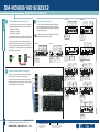
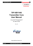
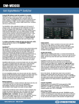
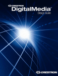
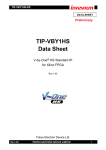
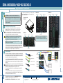
DM-MD8X8/16X16/32X32
quickstart guide
DigitalMedia™ Switchers
1
Before Starting
!
CAUTION: Do not connect power cords until instructed to do so.
B. Cards may be installed in any of the slots provided,
but it is suggested that the cards be installed into the
slots in numerical order.
NOTE: Before beginning any of these QuickStart procedures, make
certain that all DigitalMedia™ cables are installed throughout the home.
DM-MD16X16
Input Slots 1 - 8
DM-MD32X32
Output Slot 1
Input Slots 9 - 16
Input Slots 1 - 16
Output Slots 1 - 4
Input Slots 17 - 32
Typical Input Card
Installation
NOTE: Unless stated otherwise, all illustrations and procedures apply
equally to all switchers.
2
Install/Replace Input/Output Cards
Input and output cards are typically installed prior to shipment of the
DigitalMedia switchers. If, however, input cards (or output cards for the
DM-MD8X8/32X32 only) need to be installed or replaced in the field,
follow the instructions below. For more information, refer to the latest
version of the DigitalMedia Card Installation Guide (Doc. 6757), available
from the Crestron website (www.crestron.com/manuals).
!
DM-MD8X8
Input Slots 1 - 4
Output Slot 1
Output Slot 2
Input Slots 5 - 8
NOTE: Make sure that the power cord is not connected before
installing any input or output cards.
A. Remove screws securing the card to be replaced or the plate covering
the card slot to be used. Insert the card into the slot side rails, and make
certain the card is fully seated before using the attached screws to secure it
in position. (Leave cover plates in place on unused card slots.)
3
Output Slot 2
‘D’ Video
Data
Connect Outputs
The illustration immediately to the right shows the special connectors used for
the three cables contained within Crestron’s DigitalMedia™ cable, plus CBL-HD
HDMI cable, and CresFiber with an SC50UM connector. Refer to the illustrations at the far right for typical wiring configurations.
A. Use DigitalMedia cable (DM-CBL-P or DM-CBL-NP), to connect switcher
outputs directly to a DM-RMC-100 Room Controller. If required, first connect to
a DM-DR Repeater and then connect the output of the Repeater to the Room
Controller.
For detailed instructions on operation and setup of the DM-DR Repeater and
the DM-RMC-100 Room Controller, refer to the latest version of their respective
Operations & Installation Guides (Doc. 6745 and Doc. 6743).
B. Use HDMI cable, CBL-HD, to connect HDMI outputs to a local HDMI
display/receiver.
C. Use two CresFiber cables to connect the ‘D’ and ‘M’ fiber outputs to the
corresponding connectors on a local DM-RMC-100-F. DMNet control data is
carried along with video data on the ‘D’ cable.
1
Output Slots 5 - 8
For details, refer to the latest version of the DM-MD8X8/16X16/32X32
DigitalMedia™ Switchers Operations Guide, Doc. 6755.
QUICKSTART DOC. 6756D (2022813, 1 of 2)
04.10
‘M’ Data
Management
DMCO-22
‘D’ Video Data
‘M’ Data Management
‘DMNet’ Control & Power
CBL-HD - HDMI Output
DM-CBL-P
or
DM-CBL-NP
DM-CBL-P
or
DM-CBL-NP
HDMI Output
DM-DR
Repeater
‘DMNet’
Control & Power
‘D’ Video and
Control Data
‘M’ Data
Management
DMCO-11
CBL-HD
Local HDMI
Display/Receiver
CresFiber - CONN-SC50UM
CresFiber DM-RMC-100-F
www.crestron.com
©2010 Specifications subject to
change without notice.
888.273.7876
201.767.3400
All brand names, product names, and trademarks
are the property of their respective owners.
DM-RMC-100
Room Controller
DM-MD8X8/16X16/32X32
NOTE: Output cards for the DM-MD16X16 are
not field configurable. If you need a different
configuration, contact Crestron customer service.
CAUTION: Input and output cards are electrostatic-sensitive devices.
Wear a grounding strap or touch the metal chassis of a known
grounded device before handling and installing cards.
DM-MD8X8/16X16/32X32
quickstart guide
DigitalMedia™ Switchers
4
5
Connect DigitaMedia Device Power Source
4
3
A. The switchers can supply internal power to connected room
controllers and repeaters up to their rated level as shown here:
DM-MD8X8 -- 55 Watts
DM-MD16X16 -- 110 Watts
DM-MD32X32 -- 220 Watts
DMC-VID-RCA-A
Connect Sources to Input Cards
VIDEO IN:
From YPb Pr, Composite
or S-Video Source
A. There are several input cards available for the switchers,
as well as a variety of possible input sources. The diagrams
shown here illustrate available input cards and show the types
of input each one supports.
AUDIO IN:
From Analog
Audio Output
IN
HDMI OUT
Pb/Y
Y
C. If the number of devices to be connected will exceed the
switcher’s power rating, connect some of them to an external 24
VDC supply by connecting the E and G terminals of their EIG
connector(s) to the + and G terminals of the (unpowered) external
supply. (Refer to the illustration.)
B. Refer to the latest version of the DigitalMedia Switchers
Operations Guide (Doc. 6755) for details.
L
24 VDC
+ G
DMC-VID-BNC
HDMI OUT:
To Local HD Display or
HDMI Input on DaisyChained DM Switcher
Pb/Y
Y
SPDIF
Pr/C/COMP
CRESTRON
DMC-VID-RCA-D
HDMI OUT :
To Local HD Display or
HDMI Input on DaisyChained DM Switcher
DMC-DVI
VIDEO IN:
From YPb Pr , Composite
or S-Video Source
DVI IN :
From DVI or RGB
Source
AUDIO IN :
From Analog
Audio Output
AUDIO IN :
From Analog
Audio Output
COMPOSITE IN
1
Y
Pb/Y
Pr/C/COMP
AUDIO IN
R
L
+ - G + -
DMC-VID-BNC
DVI-I
USB HID
CRESTRON
DMC-DVI
USB HID:
To PC Source
2
CRESTRON
DIGITAL MEDIA
D
M
Connect to a Second Switcher (if necessary)
AUDIO OUT
R
L
NET
24 A B G
DMC-CAT
HDMI OUT:
To Local HD Display or
HDMI Input on DaisyChained DM Switcher
Connection to the second switcher consists of connecting the
HDMI output of the input cards in the primary switcher to HDMI
input cards installed on the second switcher.
DIGITAL MEDIA
D
M
AUDIO OUT:
To 2-Channel
Audio Input
AUDIO OUT
R
L
NET
24 A B G
DMC-CAT-DSP
CRESTRON
NET:
From DigitalMedia
Transmitter or
DigitalMedia Switcher
DMC-F-DSP
DM:
From DigitalMedia
Transmitter or
DigitalMedia Switcher
DM:
From DigitalMedia
Transmitter or
DigitalMedia Switcher
AUDIO OUT:
To 2-Channel
Audio Input
FIBER IN
D
M
AUDIO OUT:
:
To 2-Channel
Audio Input
FIBER IN
AUDIO OUT
R
L
HDMI OUT
CRESTRON
HDMI OUT
HDMI OUT :
To Local HD Display or
HDMI Input on DaisyChained DM Switcher
NET:
From DigitalMedia
Transmitter or
DigitalMedia Switcher
DMC-F
Secondary Switcher
DM:
From DigitalMedia
Transmitter or
DigitalMedia Switcher
AUDIO OUT:
To 2-Channel Audio
Input
CRESTRON
Primary Switcher
USB HID:
To Source
DMC-CAT-DSP
DM:
From DigitalMedia
Transmitter or
DigitalMedia Switcher
Connection to a second switcher allows expanded distribution
of the input sources connected to the primary switcher.
DMC-HD
CRESTRON
HDMI OUT :
To Local HD Display or
HDMI Input on DaisyChained DM Switcher
COMPOSITE IN:
From Composite
Video Sources
DMC-CAT
HDMI OUT
AUDIO OUT
L
R
USB HID
DMC-VID4
HDMI OUT:
To Local HD Display or
HDMI Input on DaisyChained DM Switcher
HDMI IN
HDMI OUT
4
3
D
M
AUDIO OUT
R
L
HDMI OUT
LASER RADIATION
DO NOT VIEW DIRECTLY WITH OPTICAL INSTRUMENTS
CLASS 1M LASER PRODUCT
DMC-F
CRESTRON
LASER RADIATION
DO NOT VIEW DIRECTLY WITH OPTICAL INSTRUMENTS
CLASS 1M LASER PRODUCT
DMC-F-DSP
:
HDMI OUT:
To Local HD Display or
HDMI Input on DaisyChained DM Switcher
HDMI OUT:
To Local HD Display or
HDMI Input on DaisyChained DM Switcher
DMC-SDI
SDI IN:
From SDI SOURCE
SDI OUT:
To SDI Device
SDI IN
AUDIO OUT :
To 2-Channel Audio
Input
SDI OUT
AUDIO OUT
R
L
CRESTRON
HDMI OUT:
To Local HD Display or HDMI
Input on Daisy-Chained DM
Switcher
2
For details, refer to the latest version of the DM-MD8X8/16X16/32X32
DigitalMedia™ Switchers Operations Guide, Doc. 6755.
QUICKSTART DOC. 6756D (2022813, 1 of 2)
04.10
www.crestron.com
©2010 Specifications subject to
change without notice.
888.273.7876
201.767.3400
All brand names, product names, and trademarks
are the property of their respective owners.
DMC-SDI
DM-MD8X8/16X16/32X32
HDMI OUT :
To Local HD Display or
HDMI Input on DaisyChained DM Switcher
HDMI OUT:
To Local HD Display or
HDMI Input on DaisyChained DM Switcher
AUDIO IN
R
L
+ - G + -
HDMI OUT
AUDIO OUT:
To 2-Channel
Audio Input
HDMI IN:
From HDMI Source
DMC-VID4
HDMI OUT
CRESTRON
EXTERNAL
POWER SUPPLY
IN
HDMI OUT
R
DMC-VID-RCA-A
SPDIF IN:
From Digital Audio
Output
VIDEO IN:
From YPb Pr, Composite
or S-Video Source
DMC-HD/HD-DSP
HDMI OUT
6
AUDIO
Pr/C/COMP
CRESTRON
™
B. Ensure that the EIG jumpers are installed and wired between
E and I for internal power to be routed to the connected devices.
INTERNAL
POWER
DMC-VID-RCA-D
DM-MD8X8/16X16/32X32
quickstart guide
DigitalMedia™ Switchers
7
8
Apply Power
Verify Video Inputs
NOTE: The switchers do not have a power switch. Power is
applied to the units by plugging in their respective power cords.
A. Turn on all available sources.
A. Connect the AC power cord to the switcher. Then connect the
power cord to AC power.
C. Press the applicable front panel IN buttons
to verify the signal type and resolution of each
video input. Typical information displayed is
shown in the illustration below. Use the Selection
Knob to scroll down and view all the information.
B. Connect power to any external 24VDC supplies that were
connected in Section 4.
B. Press the front panel INFO button.
INFO
Name: 1
Signal Type: Component
Resolution: 1920x1080
Video Type: Interlaced
Frame Rate: 30fps
Aspect Ratio: 16:9
INFO Button
9
9
Manual Routing of Input Sources
USB
VIDEO
AUDIO
ENTER
Front panel controls may be used to route input sources to one or more of the
available outputs.
IN
Source Buttons/LEDs
A. Press ROUTE, then press one or more of the AUDIO, VIDEO, and/or USB
buttons to select the signal type(s) you wish to route.
B. Press the desired input source buttons (IN). The corresponding LED will light. The
LEDs of any outputs the input (or input combination) is currently connected to will also
light.
C. Press one or more of the output buttons (OUT). The corresponding LED(s) will
flash to indicate it is not yet routed.
D. Press the ENTER button to actually route the source; the LED(s) will be on
steady, and the display will show the input type and the outputs to which it is routed.
To disconnect an input source from an output, press ROUTE, then press the desired
output button. The display will show “IN None”. Press ENTER and the output will be
disconnected from the input.
ROUTE
OUT
Output Buttons/LEDs
3
For details, refer to the latest version of the DM-MD8X8/16X16/32X32
DigitalMedia™ Switchers Operations Guide, Doc. 6755.
QUICKSTART DOC. 6756D (2022813, 2 of 2)
04.10
www.crestron.com
©2010 Specifications subject to
change without notice.
888.273.7876
201.767.3400
All brand names, product names, and trademarks
are the property of their respective owners.
DM-MD8X8/16X16/32X32
Selection Knob
IN
Source Buttons
DM-MD8X8/16X16/32X32
quickstart guide
DigitalMedia™ Switchers
10
Commission System
HDCP Check
A. The initial setup provided by this QuickStart guide involves the two
Commission System functions: HDCP Check and Data Rate Check, part
of the Installer Tools mode procedures. All other Installer Tools mode
procedures are described in the latest version of the DigitalMedia Switchers Operations Guide (Doc. 6755).
B. Following completion of Steps 8 and 9 on page 3, press the MENU
button once or twice until Enter Password is displayed. You need to enter
a password to continue. The default password is 1 2 3 4. Use the IN
buttons to enter the pasword, then press ENTER to initiate the Installer
Tools mode. This mode provides a series of menus and sub-menus that
let you perform a first time setup and basic configuration options.
1. Non-HDCP Card
2. Will be Tested
3. Will be Tested
Back
The HDCP Check verifies that each HDMI
source can hold enough keys to be routed to
any output. If possible distribution is larger
than the maximum number of HDCP keys,
then the source cannot be routed to all
outputs simultaneously, and an error message
will be displayed. Refer to the latest version of
the DigitalMedia Design Guide (Doc. 4789) for
details.
Commission System
HDCP Check
Data Rate Check
Installer Tools
Inputs
Outputs
Network
Control
Message Log
Commission System
Use the Selection Knob to
highlight the input to be tested,
and press OK to begin the test.
OK
HDCP Check Status
All devices can be routed
to all outputs simultaneously
Press LIST to see results.
DONE
LIST
Use the << and >>
softbuttons to check
other inputs.
Select Outputs to Test
Data Rate Check
* Digital Media
Category 6
Category 5e
* Kid’s Room
* Living Room
* Kitchen
All
None
Please verify that all sources and
selected endpoints are powered
on before proceeding.
OK
Next
HDCP Check Complete
Test in Progress . . .
Confirm DM Cable Type
Next
The data rate check ensures that each cable is
able to support all video formats that you are
using. If the cables are not able to show the
desired resolutions, you may need to install a
DM-DR Repeater, sold separately, to decrease the
length of individual cables.
Data Rate Check
ENTER Button
NOTE: The switcher controls the IP setup of connected DM-RMC-100s.
•
When the switcher is set to DHCP on, all DM-RMC-100s will also be set to DHCP on.
•
When the switcher is set to DHCP off, all DM-RMC-100s and input cards with USB
connectors will also be set to DHCP off and their static IP address will be set by the
switcher in the following fashion:
HDCP Check Results
Input 1 (DVD)
Max HDCP Keys: 9
Possible Destinations: 8
DONE <<
>>
Data Rate Check - Success
Test in Progress . . .
Kids’ Room – 2.22Gbps (1080p
OR
Typical Resolution/Data Rate
Configurations
MENU Button
Soft Buttons
HDCP Check Status
Please verify that all sources
and endpoints are powered
on before proceeding.
OK
RESOLUTION
DATA RATE
480p 60Hz
1024X768 60Hz
720p 60Hz
1280X1024 30Hz
1080i 30Hz
1080p 24Hz
1080p 60Hz
1920X1200 60Hz
Deep Color
810Mbps
1.95Gbps
2.22Gbps
3.24Gbps
2.22Gbps
2.22Gbps
4.44Gbps
4.62Gbps
6.75Gbps
Living Room – 6.75Gbps (Deep
Kitchen – 4.44Gbps (1080p 60
Resolution
Done
Data Rate Check - Error
Kids’ Room – No Video
Living Room – No Video
Kitchen – 4.44Gbps (1080p 60
Resolution
Done
To view the resolution of the
signal, press the Resolution
softbutton. (The softbutton name
changes to Data Rate.) Refer to
the adjacent table for typical
resolution/data rate configurations.
Press the Done softbutton when
the tests are finished.
<DM-MD8X8 IPaddress> + <slot #> = <DM-RMC IP address>
11 Setup EDID Configuration Using DM Tools
EX: DM-MD8X8: 192.168.1.200
DMC-HD (slot 1): 192.168.1.201
DM-RMC-100 output 1 (slot 17): 192.168.1.217
DM-RMC-100 output 8 (slot 24): 192.168.1.224
Selection Knob
Input Source
Buttons (IN)
Configure the switcher’s EDID information using Crestron’s
DigitalMedia Tools application.
This reduces the time required to set up the IP configuration of DM devices.
For details on setting IP addresses of the input and output cards for each switcher, refer
to the latest version of the DigitalMedia Switchers Operations Guide (Doc. 6755).
4
For details, refer to the latest version of the DM-MD8X8/16X16/32X32
DigitalMedia™ Switchers Operations Guide, Doc. 6755.
QUICKSTART DOC. 6756D (2022813, 2 of 2)
04.10
www.crestron.com
©2010 Specifications subject to
change without notice.
888.273.7876
201.767.3400
All brand names, product names, and trademarks
are the property of their respective owners.
Open Crestron Toolbox™ – click on the toolbar DMTool icon ( ) and
connect to your DM switcher. Visit www.crestron.com/digitalmedia
for more information on using the DM Tools.
DM-MD8X8/16X16/32X32
1. Use the Selection Knob to scroll through the list of
functions until “Commission System” is highlighted, and
press ENTER to select it.
2. Follow the on-screen instructions for each function.
3. Press the ENTER button to select an on-screen choice.
4. Use soft buttons to select choices at the bottom of a menu
screen.
5. The MENU button always takes you back to the previous
menu.
6. When all Installer Tools mode functions are completed, use
the MENU button to exit.
Advanced setup information and operational details are covered in
the latest version of the DigitalMedia Switchers
Operations Guide (Doc. 6755).
HDCP Check
The HDCP check will result
in all routes being
cleared. Continue?
No
Yes