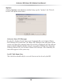
1
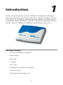
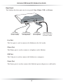
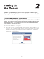
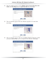
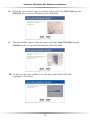
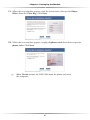
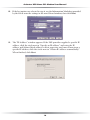
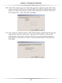
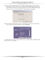
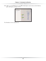
USB Home
DSL Modem
User Manual
Table of Contents
1 Introduction
1
Package Contents
Minimum System Requirements
Technical Support
Modem Features
2 Setting Up the Modem
1
2
2
3
5
Connecting a Computer to the Modem
Configuring the Modem
5
13
3 Using the Home DSL System Monitor
21
Home DSL Manager Icon
Home DSL Monitor
21
22
4 Troubleshooting and FAQs
A Reference
27
29
Locating Computer Information
Locating Windows Operating System Files
B Specifications
29
30
33
General
LED Indicators
Environmental
33
33
34
C Glossary
Notices
35
39
Regulatory Compliance Notices
Modifications
Limited Warranty
39
39
41
i
Actiontec Wireless-Ready DSL Gateway User Manual
ii
1
Introduction
Thank you for purchasing the Actiontec USB Home DSL Modem. The Modem provides connection speeds up to 125 times faster than a standard 56K modem. This easyto-set-up, easy-to-use product is perfect for the home computer user. If you want to
dramatically accelerate your Internet connection and take your computing to the next
level, the Actiontec USB Home DSL Modem is one of the keys to your success.
Package Contents
Actiontec USB Home DSL Modem
Power adapter
DSL cable
USB cable
Phone filters
Installation CD (includes user manual)
Quick start guide
Warranty and registration card
1
Actiontec USB Home DSL Modem User Guide
Minimum System Requirements
Active DSL service
Computer with a USB connection
Microsoft Windows 98, Windows 98 Second Edition (SE), Windows
Millennium Edition (Me), Windows 2000, Windows XP
Internet Explorer 4.0 or higher (5.x recommended) or Netscape Navigator
4.0 or higher (4.7 recommended)
Technical Support
Actiontec Electronics prides itself on making durable, high-quality, high-performance products. If you need assistance, the Actiontec Technical Support Department is
available 24 hours a day, every day, to provide professional support.
Actiontec Electronics, Inc.
760 N. Mary Avenue
Sunnyvale, CA 94085
Technical Support
Phone: 888.436.0657
E-mail: [email protected]
Internet: www.actiontec.com/support
2
Chapter 1 Introduction
Modem Features
The Modem features two LEDs (lights) on its front panel, and series of ports on its
rear panel. We recommend the user become familiar with these features before
installing or setting up the Modem.
Front Panel
There are two LEDs (light emitting diodes, or lights) on the front panel of the
Modem, as shown in the figure, below.
PW
LK
PWR LED
The PWR (Power) LED glows green when power is supplied to the Modem.
When it flashes, the Modem is going through its initialization process.
LK LED
The LK (Link) LED glows green when the DSL connection is active. When it
blinks, data is traveling across the connection
3
Actiontec USB Home DSL Modem User Guide
Rear Panel
The Modem has four ports on its rear panel: Line, Phone, USB, and Power.
USB
Line
DSL Cable
(from Line Port
to DSL Outlet)
Power
Phone
Phone Cable
(from Phone Port
to Telephone)
USB Cable
(from USB Port
to Computer)
Power Adapter
(from Power Port
to Power Outlet)
Line Port
The Line port is used to connect the Modem to the DSL outlet.
Phone Port
The Phone port is used to connect a telephone to the Modem.
USB Port
The USB port is used to connect the Modem to a computer.
Power Port
The Power port is used to connect the Modem’s power adapter to a wall outlet.
4
2
Setting Up
the Modem
Setting up the Modem involves two basic steps: connecting a computer to the
Modem, and configuring the Modem to activate the DSL connection and load the
software drivers.
Connecting a Computer to the Modem
The instructions in this section parallel the steps contained in the Actiontec Installation
Buddy™, which provides a visual guide to connecting the Modem to a computer and
installing phone filters. It is recommended the user run the Installation Buddy first,
before attempting any other procedures.
To connect the Modem to a computer:
1. Insert the Actiontec Installation Buddy CD-ROM in the CD-ROM drive of the
computer. The Installation Buddy will start automatically. Wait until the following screen appears in your Internet browser window, read the onscreen
instructions, then click Next.
5
Actiontec USB Home DSL Modem User Manual
2. The next window appears. Get the Modem, Power Cord, USB Cable, DSL
Cable, and Clear Bag from the Quick Start Kit, then click Next.
3. The next window appears. Place the Modem upright in its stand, then
click Next.
4. The next window appears. Take the gray Power Cord and plug the smaller
end into the Power Port on the rear panel of the Modem. Click Next.
6
Chapter 2 Setting Up the Modem
5. The next window appears. Plug the larger end of the Power Cord into a
Power Outlet in a wall, then click Next.
6. When the next window appears, confim the PW (Power) Light on the front
of the Modem glows solid green, orange, or red. Click Next.
7. Another window appears. Plug one end of the gray DSL Cable into the Line
Port on the rear panel of the Modem, then click Next.
7
Actiontec USB Home DSL Modem User Manual
8. When the next window appears, plug the other end of the DSL Cable into the
Wall Jack closest to your computer, then click Next.
9. The next window appears. Plug the square end of the beige USB Cable into the
USB Port on the rear panel of the Modem, then click Next.
10. As shown in the next window, leave the other end of the USB cable
unplugged. Click Next.
8
Chapter 2 Setting Up the Modem
11. When the next window appears, read the instructions, then get the Phone
Filters from the Clear Bag. Click Next.
12. When the next window appears, unplug all phone cords from their respective
phone jacks. Click Next.
☞
Note: Do not remove the DSL Cable from the phone jack near
the computer.
9
Actiontec USB Home DSL Modem User Manual
13. The following window appears. Plug a phone filter in every phone jack, then
click Next.
☞
Note: Do not install a phone filter on the DSL Cable in the
phone jack near the computer.
14. When the next window appears, plug the phone cords unplugged in step 12
into the phone filters installed in step 13, then click Next.
15. Another window appears. If a phone needs to plugged into the Modem, click Yes.
If not, click No.
10
Chapter 2 Setting Up the Modem
16. If Yes was chosen in step 15, the next window appears. Unplug the phone
cable connected to the computer or nearby phone jack. Click Next.
If No was chosen in step 15, go directly to step 19.
☞
Note: Do not remove the DSL Cable from the phone jack near
the computer.
17. In the next window, plug a phone filter on the loose end of the phone cord
unplugged in step 16, then click Next.
☞
Note: Do not install a phone filter on the DSL Cable in the
phone jack near the computer.
11
Actiontec USB Home DSL Modem User Manual
18. When the next window appears, plug the phone filter into the Phone Port
on the rear panel of the Modem. The Modem and phone should be connected exactly as shown in the picture, below. Click Next.
19. When the next window appears, the Modem is connected to a computer.
Click Finish.
Next, go to “Configuring the Modem” on page 13.
12
Chapter 2 Setting Up the Modem
Configuring the Modem
The following procedure details the steps involved in configuring the Modem to
activate the DSL connection and load the software drivers. The Information
Worksheet from the Internet Service Provider (ISP) must be available to complete
this procedure. If this document has not been received, contact the ISP immediately.
1. Insert the rectangular end of the USB cable into a USB port on the front or
back of the computer.
☞
Note: A USB port is shaped like a thin rectangle about 1/4 inch
by 1/2 inch, and may be vertically or horizontally oriented.
2. Power up the computer. After the computer boots, Windows detects the
Modem. When the “Add New Hardware Wizard” window appears, select
Search for the best driver for your device (Recommended) by clicking the
circle next to the text, then click Next.
☞
Note: The windows shown in steps 2 through 5 are for Windows
98. Your windows may appear slightly different.
13
Actiontec USB Home DSL Modem User Manual
3. In the next window, select Specify a location by clicking in the check box
next to the text. Then, enter d:\driver in the text box (where “d” is the
drive letter of the CD-ROM drive). Click Next.
4. When the next window appears, make sure that the text below “Location of
driver” displays the correct location of the driver, then click Next.
5. The final wizard window appears, stating that the software has been installed.
Click Finish.
14
Chapter 2 Setting Up the Modem
6. The first “Actiontec Home DSL Configuration Wizard” window appears. Read
the instructions, then click Next.
7. In the next window, select the one of the options by clicking on the circle next
to the text.
• Select the first option (“Preconfigured”) if your DSL provider is listed in the
“Telephone Company” list box. (Also select an “Internet Service Provider,” if
applicable.)
• Select the second option (“supplied a file”) if your DSL provider supplied a
data disk containing configuration information.
• Select the last option (“configure my DSL modem manually”) if your DSL
provider supplied an information worksheet. After selecting an option, click
Next.
☞
Note: If you selected the first option in step 8, go directly to step
14. If you selected the second option, insert the data disk into
the computer, load the settings, then go to step 14.
15
Actiontec USB Home DSL Modem User Manual
8. If the last option was selected in step 8, use the Information Worksheet provided
by the ISP to enter the settings in the next Wizard window, then click Next.
9. The “IP Address” window appears. If the DSL provider supplied a specific IP
address, click the circle next to “Specify an IP address” and enter the IP
address and Subnet Mask address in their respective text boxes.If not given a
specific IP address, click the circle next to “Obtain IP address automatically.”
When finished, click Next.
16
Chapter 2 Setting Up the Modem
10. The “DNS” window appears. If the DSL provider supplied specific DNS information, click the circle next to “Enable DNS” and enter the information in the
proper text boxes. If not given specific DNS information, click the circle next
to “Disable DNS.” When finished, click Next.
11. The “Gateway” window appears. If the DSL provider supplied specific gateway
information, click the circle next to “Specify an IP Gateway” and enter the
information in the proper text boxes.If not given specific gateway information, click the circle next to “Obtain Gateway automatically.” When finished,
click Next.
17
Actiontec USB Home DSL Modem User Manual
12. The “WINS” window appears. If the DSL provider supplied specific WINS
information, click the circle next to “Enable WINS Resolution” and enter the
information in the proper text boxes.If not given specific WINS information,
click the circle next to “Disable WINS.” When finished, click Next.
13. The final Wizard windows appears, containing a summary of the configuration settings. Read the instructions, then click Finish.
An “Information” window appears while the new configuration is applied and the
software drivers are loaded.
18
Chapter 2 Setting Up the Modem
14. Make sure the PW (Power) and LK (Link) lights on the front of the Modem
glow solid green, orange, or red.
The Modem is now ready to use.
19
Actiontec USB Home DSL Modem User Manual
20
Using the Home DSL
System Monitor
3
To check the operation of the Actiontec USB Home DSL Modem and view its connection status, use the Home DSL System Monitor.
Home DSL Manager Icon
After the Modem has been set up properly (see chapter 2, “Setting Up the Modem,”
on page 5 for more details), the “Actiontec Home DSL Manager” icon will appear in
the system tray of the computer’s desktop (next to the clock in the lower right corner, as shown in the red oval in the figure below).
The icon itself displays some details regarding the connection to the Modem:
Green bar above red/green arrows: indicates the Modem is connected and working properly. The arrows blink green when accessing a Web site and transmitting
and receiving data; when they are solid green, the Modem is downloading or
uploading larger data files. If the arrows are red, the Modem is connected to the
Internet, but not accessing any Web sites.
Yellow bar above red arrows: indicates the Modem is trying to connect to the
Internet. This process normally takes less than 10 seconds, unless there is a problem with the phone line or DSL service. If the bar does not turn green after 20 seconds, check all connections to the Modem. If the yellow bar remains visible, contact the Internet Service Provider (ISP).
21
Actiontec USB Home DSL Modem User Manual
Red bar above red arrows: indicates an error has occurred with the Modem or its
software. If this occurs, check all connections to the Modem, and if the problem
persists, go to Start, Settings, Control Panel, Device Manager, and check for any yellow exclamation points in the “Modems” section, call Actiontec Technical Support.
Gray bar above red arrows: indicates the Modem is working properly, but no connection with the ISP has been established. If this condition persists, contact the ISP.
Home DSL Monitor
Double-clicking on the Home DSL Manager icon generates the “Actiontec Home
DSL Monitor” window.
The Monitor window contains four tabs: Status, Provider Info, Versions, and
Options.
Status
Clicking Status in the Monitor window brings up the “Status” tab, as shown in the
figure above. This tab features statistics and other information regarding the
Modem and its connection.
Modem Status
The “Modem Status” text box displays the current status of the Modem connection.
22
Chapter 3 Using the Home DSL System Monitor
Connection Rates
The two text boxes in “Connection Rates” section(“Upstream” and
“Downstream”) indicate the speed (in kilobits per second) of the Modem’s connection.
Payload
The graph and two text boxes in in the “Payload” section indicate the amount of
traffic passing through the Modem.
MAC Address
The “MAC Address” text box displays the MAC (Media Access Control) address
of the Modem. This address is unique for every networkable device.
VPI/VCI Value
The “VPI/VCI Value” text box displays the Virtual Path Identifier/Virtual Ciruit
Identifier value. This value cannot be changed from here.
Current Protocol
The “Current Protocol” text box displays the network protocol currently used by
the Modem.
Disconnect
Clicking the “Disconnect” button disconnects the Modem from the Internet.
23
Actiontec USB Home DSL Modem User Manual
Provider Info
Clicking Provider Info in the Monitor window brings up the “Provider Info” tab.
This tab features information regarding the Modem’s DSL and ISP provider.
DSL Provider
The “DSL Provider” text box dispays the current DSL provider to which the
Modem is connected.
ISP Provider
The “ISP Provider” text box dispays the current ISP provider to which the Modem
is connected.
Edit Info
Clicking the “Edit Info” button generates an “Information” window. The DSL
provider can be changed from this window.
24
Chapter 3 Using the Home DSL System Monitor
Versions
Clicking Versions in the Monitor window brings up the “Versions” tab. This tab
features statistics and other information regarding the Modem’s software and firware versions.
Platform
The “Platform” text box displays the version of the operating system currently running on the computer connected to the Modem.
Application Version
The “Application Version” text box displays the version of the Home DSL System
Monitor currently running on the computer connected to the Modem.
Operation Mode
The “Operation Mode” text box displays the kind of connection (USB, Ethernet)
with which the Modem is connected to the computer.
Driver Version
The “Driver Version” text box displays the Modem’s software driver version
Firmware Version
The “Firmware Version” text box displays the Modem’s firmware version.
25
Actiontec USB Home DSL Modem User Manual
Options
Clicking Options in the Monitor window brings up the “Options” tab. This tab
features two option check boxes.
Actiontec Home DSL Manager
If a check is displayed in the box next to “Automatically run Actiontec Home
DSL Manager on system boot,” the Home DSL Manager icon will appear in the
system tray when the computer boots. If no check is displayed, the icon will not
appear, and the Monitor window must be accessed by clicking Start, Programs,
Actiontec Home DSL, and Actiontec Home DSL Manager. After rebooting, the
icon will reappear in the system tray.
For RFC1483 Mode Only
This check box should only be accessed if instructed to do so by the ISP.
26
Troubleshooting
and FAQs
4
This chapter contains a list of solutions for problems the user may encounter while
using the Modem, as well as answers to some of the more frequently asked questions about the Modem.
I have more than four phones in my home. Where can I get more microfilters?
The USB Home DSL Modem package includes four microfilters. If more are
needed, contact a local electronics retailer.
It has been a while since I signed up for DSL service with my Internet Service
Provider and my service still has not been activated. What should I do?
Contact the Internet Service Provider to find out about the status of the
DSL service.
My computer cannot find my USB Home DSL Modem.
If the modem installation has been performed and the computer is not finding
the modem, check all connections, then click Start on the computer’s desktop.
Select Settings, Control Panel, System, and Device Manager. If you see a yellow exclamation mark or red “x” next to the “Home DSL Modem” under
“Network Adapters” in the “Device Manager” window, contact Actiontec
Technical Support.
Can I share my DSL line with more than one computer in my home?
Yes, but only with an Ethernet card.
Can I talk on the phone while being connected to the Internet?
Yes.
27
Actiontec USB Home DSL Modem User Manual
Can I fax over DSL?
No. You still need to send your faxes over your regular phone line using an analog modem or fax machine.
Do I have to pay my phone company and my ISP for DSL service?
No. By signing up with an Internet Service Provider for DSL service, the only
DSL bill you will pay is to your ISP.
How do I know my modem is functioning properly?
See chapter 3, “Using the Home DSL System Monitor,” for more information
about monitoring the operation and connection status of the Modem.
28
A
Reference
This appendix contains information about various topics, including accessing
information about your Windows computer and wiring under special circumstances.
Locating Computer Information
The following procedure is valid for Windows 98, 98 SE, Me, 2000, and XP.
1. From the desktop, right-click on My Computer.
2. Select Properties from the menu that appears.
3. When the “System Properties” window appears, select General.
The version of the operating system, processor type, and amount of RAM
installed in the computer are listed here.
4. Close the System Properties window.
5.
From the desktop, double-click on My Computer.
6. Right-click the icon representing your hard disk. For example: Local Disk (C:).
Some computers have multiple hard disks.
7. From the menu that appears, select Properties.
8. When the window appears, select General.
9. The Free space value is the available space on the hard disk.
10. Close all windows.
29
Actiontec USB Home DSL Modem User Manual
Locating Windows Operating System Files
If the operating system files reside on the hard drive of the computer, follow the
instructions below to locate them. If the files are not on the hard drive, they must
be loaded from the installation disks.
Windows 98, 98 SE
1. From the desktop, click Start.
2. When the menu appears, select Find, then Files or Folders.
3. When the “Find: All Files” window appears, select Name & Location.
4. In the “Named” text box, enter:
*.cab
5. Click the down arrow next to the “Look In” text box and select My
Computer from the list that appears.
6. Click Find Now.
7.
When the search is complete, note the directory path that appears most often
in the “In Folder” column. For example: C:\WINDOWS \SYSTEM.
8. The Windows operating system files are located in this directory. Write down
the directory path for future reference.
9.
Close the Find: All Files window.
Windows Me, 2000
1. From the desktop, click Start.
2. Select Search, then For Files and Folders.
3a. Windows Me: The “Search Results” window appears. In the “Search for files
or folders named” text box, enter:
*.cab
3b. Windows 2000: The “Search Results” window appears. In the “Search for files
or folders named” text box, enter:
i386
30
Appendix A Reference
4. Click the down arrow next to the “Look in” text box and select My
Computer from the list that appears.
5.
Click Search Now.
6a. Windows Me: When the search is complete, note the directory path that
appears most often in the “In Folder” column. For example:
C:\WINDOWS \OPTIONS\INSTALL.
6b. Windows 2000: When the search is complete, note the directory path that
appears most often in the “In Folder” column. For example:
C:\WINNT \Driver Cache.
7. The Windows operating system files are located in this directory. Write down
the directory path for future reference.
8.
Close the Search Results window.
Windows Me, 2000
1. From the desktop, click Start.
2. Select Search, then For Files and Folders.
3. The “Search Results” window appears. In the panel at left titled “What do you
want to search for?”, click All files and folders.
4. Another panel, titled “Search by any or all of the criteria below” appears. In
the “Look in” text box, click the down arrow and select My Computer from
the menu that appears.
5. In the “All or part of the file name” text box, enter:
i386
6.
Click Search.
7. When the search is complete, note the directory path that appears most often
in the “In Folder” column. For example: C:\WINDOWS \Driver Cache\.
8. The Windows operating system files are located in this directory. Write down
the directory path (followed by “\i386”) for future reference.
9.
Close the Search Results window.
31
Actiontec USB Home DSL Modem User Manual
32
B
Specifications
General
Model Number
UD800TP (USB Home DSL Modem)
Dimensions
Length: 5.375 in.
Width: 4.35 in
Height: 1.25 in
Standards
ANSI specification T1.413 issue 2
G.992.1 (G.dmt)
G.992.2 (G.lite)
WAN
Full-rate DSL modem
Speed
Up to 8 Mbps downstream, 640 Kbps upstream
Cabling Type
Phone
USB
LED Indicators
PWR (Power), LK (Link)
33
Actiontec USB Home DSL Modem User Manual
Environmental
Power Input
External, +5V +- 5% @ 1.5 A
Certifications
FCC Class C (part 15, 68)
UL
Operating Temperature
0º C to 40º C (32ºF to 104ºF)
Storage Temperature
-20ºC to 70ºC (-4ºF to 158ºF)
Operating Humidity
10% to 85% non-condensing
Storage Humidity
5% to 90% non-condensing
34
C
Glossary
Access Point
A device that allows wireless clients to connect to one another. An access point
can also act as a bridge between wireless clients and a “wired” network, such as
an Ethernet network. Wireless clients can be moved anywhere within the coverage area of the access point and remain connected to the network. If connected
to an Ethernet network, the access point monitors Ethernet traffic and forwards
appropriate Ethernet messages to the wireless network, while also monitoring
wireless traffic and forwarding wireless client messages to the Ethernet network.
Client
A desktop or mobile computer connected to a network.
DHCP (Dynamic Host Configuration Protocol)
A protocol designed to automatically assign an IP address to every computer on
a network.
DNS (Domain Name System) Server Address
Allows Internet host computers to have a domain name and one or more IP
addresses. A DNS server keeps a database of host computers and their respective
domain names and IP addresses so that when a user enters a domain name into
a Web browser, the user is sent to the proper IP address. The DNS server address
used by computers on the home network corresponds to the location of the
DNS server the ISP has assigned.
DSL (Digital Subscriber Line) Modem
A modem that uses existing phone lines to transmit data at high speeds.
Encryption
Provides security for wireless data transmissions.
ESSID (Extended Service Set Identifier)
A unique identifier for a wireless network.
Ethernet Network
A standard wired network configuration using cables and hubs.
35
Actiontec USB Home DSL Modem User Manual
Firewall
Prevents users outside the network from accessing and/or damaging files or
computers on the network.
Gateway
A device that manages the data traffic of a network, as well as data traffic to and
from the Internet.
IP (Internet Protocol) Address
A series of four numbers separated by periods identifying a unique Internet
computer host.
ISP Gateway Address
An IP address for the Internet gateway. This address is only required when using
a cable or DSL modem.
ISP (Internet Service Provider)
A business that connects individuals or businesses to the Internet.
LAN (Local Area Network)
A group of computers and devices connected together in a relatively small area
(such as a house or an office). A home network is considered a LAN.
MAC (Media Access Control) Address
The hardware address of a device connected to a network.
NAT (Network Address Translation)
Allows all computers on a network to use one IP address, enabling access to the
Internet from any computer on the the network without purchasing more IP
addresses from an ISP.
PC Card
An Ethernet adapter connected to the PCMCIA slot in a computer, enabling the
communication with the Gateway.
PPPoE (Point-to-Point Protocol over Ethernet)
A method of secure data transmission.
36
Appendix C Glossary
Subnet Mask
A set of four numbers configured like an IP address used to create IP address
numbers used within a particular network only.
TCP/IP (Transmission Control Protocol/Internet Protocol)
The standard protocol for data transmission over the Internet.
WAN (Wide Area Network)
A network connecting computers located in separate areas, (i.e., different buildings, cities, countries). The Internet is a WAN.
WECA (Wireless Ethernet Compatibility Alliance)
An industry group that certifies cross-vender interoperability and compatibility
of IEEE 802.11b wireless networking products and promotes the standard for
enterprise, small business, and home environments.
WLAN (Wireless Local Area Network)
A group of computers and other devices connected wirelessly in a small area.
37
Actiontec USB Home DSL Modem User Manual
38
Notices
Regulatory Compliance Notices
Class B Equipment
This equipment has been tested and found to comply with the limits for a Class B
digital device, pursuant to Part 15 of the FCC Rules. These limits are designed to
provide reasonable protection against harmful interference in a residential installation. This equipment generates, uses, and can radiate radio frequency energy and,
if not installed and used in accordance with the instructions, may cause harmful
interference to radio communications. However, there is no guarantee that interference will not occur in a particular installation. If this equipment does cause
harmful interference to radio or television reception, which can be determined by
turning the equipment off and on, the user is encouraged to try to correct the
interference by implementing one or more of the following measures:
Reorient or relocate the receiving antenna;
Increase the separation between the equipment and receiver;
Connect the equipment to an outlet on a circuit different from that to
which the receiver is connected;
Consult the dealer or an experienced radio or television technician for help.
Modifications
The FCC requires the user to be notified that any changes or modifications made
to this device that are not expressly approved by Actiontec Electronics, Inc., may
void the user’s authority to operate the equipment.
Declaration of conformity for products marked with the FCC logo – United States
only.
This device complies with Part 15 of the FCC Rules. Operation is subject to the
following two conditions:
1.
This device may not cause harmful interference;
39
Actiontec USB Home DSL Modem User Manual
2. This device must accept any interference received, including interference that
may cause unwanted operation.
To comply with FCC RF exposure compliance require☞ Note:
ments, the antenna used for this transmitter must be installed to
provide a separation distance of at least 20 cm from all persons
and must not be co-located or operating in conjunction with
any other antenna or transmitter.
For questions regarding your product or the FCC declaration, contact:
Actiontec Electronics, Inc.
760 North Mary Ave.
Sunnyvale, CA 94086
United States
Tel: (408) 752-7700
Fax: (408) 541-9005
40
Limited Warranty
Hardware: Actiontec Electronics, Inc., warrants to the end user (“Customer”) that
this hardware product will be free from defects in workmanship and materials,
under normal use and service, for twelve (12) months from the date of purchase
from Actiontec Electronics or its authorized reseller.
Actiontec Electronics’ sole obligation under this express warranty shall be, at
Actiontec’s option and expense, to repair the defective product or part, deliver to
Customer an equivalent product or part to replace the defective item, or if neither
of the two foregoing options is reasonably available, Actiontec Electronics may, in its
sole discretion, refund to Customer the purchase price paid for the defective product. All products that are replaced will become the property of Actiontec Electronics,
Inc. Replacement products may be new or reconditioned. Actiontec Electronics warrants any replaced or repaired product or part for ninety (90) days from shipment,
or the remainder of the initial warranty period, whichever is longer.
Software: Actiontec Electronics warrants to Customer that each software program
licensed from it will perform in substantial conformance to its program specifications, for a period of ninety (90) days from the date of purchase from Actiontec
Electronics or its authorized reseller. Actiontec Electronics warrants the media containing software against failure during the warranty period. The only updates that
will be provided are at the sole discretion of Actiontec Electronics and will only be
available for download at the Actiontec Web site, www.actiontec.com. Actiontec
Electronics’ sole obligation under this express warranty shall be, at Actiontec
Electronics’ option and expense, to refund the purchase price paid by Customer for
any defective software product, or to replace any defective media with software
which substantially conforms to applicable Actiontec Electronics published specifications. Customer assumes responsibility for the selection of the appropriate applications program and associated reference materials. Actiontec Electronics makes no
warranty or representation that its software products will meet Customer’s
requirements or work in combination with any hardware or applications software
products provided by third parties, that the operation of the software products will
be uninterrupted or error free, or that all defects in the software products will be
corrected. For any third-party products listed in the Actiontec Electronics software
product documentation or specifications as being compatible, Actiontec
Electronics will make reasonable efforts to provide compatibility, except where the
non-compatibility is caused by a “bug” or defect in the third party’s product or
from use of the software product not in accordance with Actiontec Electronics
published specifications or user guide.
41
Actiontec USB Home DSL Modem User Manual
THIS ACTIONTEC ELECTRONICS PRODUCT MAY INCLUDE OR BE BUNDLED
WITH THIRD-PARTY SOFTWARE, THE USE OF WHICH IS GOVERNED BY A SEPARATE END-USER LICENSE AGREEMENT.
THIS ACTIONTEC ELECTRONICS WARRANTY DOES NOT APPLY TO SUCH THIRDPARTY SOFTWARE. FOR THE APPLICABLE WARRANTY, PLEASE REFER TO THE
END-USER LICENSE AGREEMENT GOVERNING THE USE OF SUCH SOFTWARE.
Obtaining Warranty Service: Customer may contact Actiontec Electronics
Technical Support Center within the applicable warranty period to obtain warranty service authorization. Dated proof of purchase from Actiontec Electronics or its
authorized reseller may be required. Products returned to Actiontec Electronics
must be pre-authorized by Actiontec Electronics with a Return Merchandise
Authorization (RMA) number marked on the outside of the package, and sent
prepaid and packaged appropriately for safe shipment, and it is recommended that
they be insured or sent by a method that provides for tracking of the package. The
repaired or replaced item will be shipped to Customer, at Actiontec Electronics’
expense, not later than thirty (30) days after Actiontec Electronics receives the
defective product.
Return the product to:
(In the United States)
Actiontec Electronics, Inc.
760 North Mary Avenue
Sunnyvale, CA 94085
Actiontec Electronics shall not be responsible for any software, firmware, information, memory data, or Customer data contained in, stored on, or integrated with
any products returned to Actiontec Electronics for repair, whether under warranty
or not.
WARRANTIES EXCLUSIVE: IF AN ACTIONTEC ELECTRONICS’ PRODUCT DOES
NOT OPERATE AS WARRANTED ABOVE, CUSTOMER’S SOLE REMEDY FOR
BREACH OF THAT WARRANTY SHALL BE REPAIR, REPLACEMENT, OR REFUND OF
THE PURCHASE PRICE PAID, AT ACTIONTEC ELECTRONICS’ OPTION. TO THE
FULL EXTENT ALLOWED BY LAW, THE FOREGOING WARRANTIES AND REMEDIES ARE EXCLUSIVE AND IN LIEU OF ALL OTHER WARRANTIES, TERMS OR
CONDITIONS, EXPRESS OR IMPLIED, EITHER IN FACT OR BY OPERATION OF
LAW, STATUTORY OR OTHERWISE, INCLUDING WARRANTIES, TERMS OR CONDITIONS OF MERCHANTABILITY, FITNESS FOR A PARTICULAR PURPOSE, SATISFACTORY QUALITY, CORRESPONDENCE WITH DESCRIPTION, AND NON-INFRINGEMENT, ALL OF WHICH ARE EXPRESSLY DISCLAIMED. ACTIONTEC ELECTRONICS
42
Limited Warranty
NEITHER ASSUMES NOR AUTHORIZES ANY OTHER PERSON TO ASSUME FOR IT
ANY OTHER LIABILITY IN CONNECTION WITH THE SALE, INSTALLATION, MAINTENANCE OR USE OF ITS PRODUCTS.
ACTIONTEC ELECTRONICS SHALL NOT BE LIABLE UNDER THIS WARRANTY IF
ITS TESTING AND EXAMINATION DISCLOSE THAT THE ALLEGED DEFECT OR
MALFUNCTION IN THE PRODUCT DOES NOT EXIST OR WAS CAUSED BY CUSTOMER’S OR ANY THIRD PERSON’S MISUSE, NEGLECT, IMPROPER INSTALLATION
OR TESTING, UNAUTHORIZED ATTEMPT TO OPEN, REPAIR OR MODIFY THE
PRODUCT, OR ANY OTHER CAUSE BEYOND THE RANGE OF THE INTENDED USE,
OR BY ACCIDENT, FIRE, LIGHTNING, OTHER HAZARDS, OR ACTS OF GOD.
LIMITATION OF LIABILITY: TO THE FULL EXTENT ALLOWED BY LAW, ACTIONTEC ELECTRONICS ALSO EXCLUDES FOR ITSELF AND ITS SUPPLIERS ANY LIABILITY, WHETHER BASED IN CONTRACT OR TORT (INCLUDING NEGLIGENCE), FOR
INCIDENTAL, CONSEQUENTIAL, INDIRECT, SPECIAL, OR PUNITIVE DAMAGES OF
ANY KIND, OR FOR LOSS OF REVENUE OR PROFITS, LOSS OF BUSINESS, LOSS OF
INFORMATION OR DATA, OR OTHER FINANCIAL LOSS ARISING OUT OF OR IN
CONNECTION WITH THE SALE, INSTALLATION, MAINTENANCE, USE, PERFORMANCE, FAILURE, OR INTERRUPTION OF ITS PRODUCT, EVEN IF ACTIONTEC
ELECTRONICS OR ITS AUTHORIZED RESELLER HAS BEEN ADVISED OF THE POSSIBILITY OF SUCH DAMAGES, AND LIMITS ITS LIABILITY TO REPAIR, REPLACEMENT,OR REFUND OF THE PURCHASE PRICE PAID, AT ACTIONTEC ELECTRONICS’ OPTION. THIS DISCLAIMER OF LIABILITY FOR DAMAGES WILL NOT BE
AFFECTED IF ANY REMEDY PROVIDED HEREIN SHALL FAIL OF ITS ESSENTIAL
PURPOSE.
Disclaimer: Some countries, states or provinces do not allow the exclusion or limitation of implied warranties or the limitation of incidental or consequential damages for certain products supplied to consumers, or the limitation of liability for
personal injury, so the above limitations and exclusions may be limited in their
application to you. When the implied warranties are not allowed to be excluded in
their entirety, they will be limited to the duration of the applicable written warranty.
This warranty gives you specific legal rights which may vary depending on local law.
Dispute Resolution: The customer may contact the Director of Technical Support
in the event the Customer is not satisfied with Actiontec Electronics’ response to
the complaint. In the event that the Customer is still not satisfied with the response
of the Director of Technical Support, the Customer is instructed to contact the
Director of Marketing. In the event that the Customer is still not satisfied with the
response of the Director of Marketing, the Customer is instructed to contact the
Chief Financial Officer and/or President.
43
Actiontec USB Home DSL Modem User Manual
Governing Law: This Limited Warranty shall be governed by the laws of the State
of California, U.S.A., excluding its conflicts of laws and principles, and excluding
the United Nations Convention on Contracts for the International Sale of Goods.
44