1
Holliston™DC
Holliston™ DC Owner’s Manual
Read and Save These Instructions!
Safety and the proper operation of your Casablanca fan both require a thorough knowledge of the product and
proper installation; therefore, before attempting to install and operate your Casablanca fan, read this owner’s
manual completely and carefully. Retain this manual for future reference.
Caution: To avoid possible electrical shock, make certain that electricity is turned off at the circuit breaker
or fuse box before attempting any installation procedure.
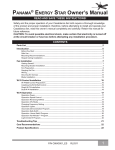
CONTENTS
Introduction . . . . . . . . . . . . . . . . . . . . . . . . . . . . . . . . . . . . . . . . . . . . . . . . . . . . . . . . . . . . . . . . . . . 5
Before You Start . . . . . . . . . . . . . . . . . . . . . . . . . . . . . . . . . . . . . . . . . . . . . . . . . . . . . . . . . . . . . . . . . . . . . 5
Safe Use . . . . . . . . . . . . . . . . . . . . . . . . . . . . . . . . . . . . . . . . . . . . . . . . . . . . . . . . . . . . . . . . . . . . . . . . . . . 5
MOUNTING RECOMMENDATIONS . . . . . . . . . . . . . . . . . . . . . . . . . . . . . . . . . . . . . . . . . . . . . . . . . 6
General Guidelines . . . . . . . . . . . . . . . . . . . . . . . . . . . . . . . . . . . . . . . . . . . . . . . . . . . . . . . . . . . . . . . . . . 6
sloped ceiling installations . . . . . . . . . . . . . . . . . . . . . . . . . . . . . . . . . . . . . . . . . . . . . . . . . . . . . . . . . . . . . 6
Fan Installation . . . . . . . . . . . . . . . . . . . . . . . . . . . . . . . . . . . . . . . . . . . . . . . . . . . . . . . . . . . . . . . . 7
Getting Started . . . . . . . . . . . . . . . . . . . . . . . . . . . . . . . . . . . . . . . . . . . . . . . . . . . . . . . . . . . . . . . . . . . . . 7
Ceiling plate Installation . . . . . . . . . . . . . . . . . . . . . . . . . . . . . . . . . . . . . . . . . . . . . . . . . . . . . . . . . . . . . . 7
Lag Screw Installation . . . . . . . . . . . . . . . . . . . . . . . . . . . . . . . . . . . . . . . . . . . . . . . . . . . . . . . . . . . . . . . . 8
Canopy Installation . . . . . . . . . . . . . . . . . . . . . . . . . . . . . . . . . . . . . . . . . . . . . . . . . . . . . . . . . . . . . . . . . . 8
Fan Preparation . . . . . . . . . . . . . . . . . . . . . . . . . . . . . . . . . . . . . . . . . . . . . . . . . . . . . . . . . . . . . . . . . . . . . 9
Hanging the Fan . . . . . . . . . . . . . . . . . . . . . . . . . . . . . . . . . . . . . . . . . . . . . . . . . . . . . . . . . . . . . . . . . . . 11
Canopy Electrical Connections . . . . . . . . . . . . . . . . . . . . . . . . . . . . . . . . . . . . . . . . . . . . . . . . . . . . . . . . 12
Canopy Hatch and cover ring Installation . . . . . . . . . . . . . . . . . . . . . . . . . . . . . . . . . . . . . . . . . . . . . . . . 12
Blade Installation . . . . . . . . . . . . . . . . . . . . . . . . . . . . . . . . . . . . . . . . . . . . . . . . . . . . . . . . . . . . . . . . . . . 13
LIGHT FIXTURE Installation (optional) . . . . . . . . . . . . . . . . . . . . . . . . . . . . . . . . . . . . . . . . . . . . . . . 14
Control Installation and Operation . . . . . . . . . . . . . . . . . . . . . . . . . . . . . . . . . . . . . . 22
switch housing and end cap Installation . . . . . . . . . . . . . . . . . . . . . . . . . . . . . . . . . . . . . . . . . . . . . . . . . . 15
Control Battery Installation . . . . . . . . . . . . . . . . . . . . . . . . . . . . . . . . . . . . . . . . . . . . . . . . . . . . . . . . . . . 22
Changing frequency setting . . . . . . . . . . . . . . . . . . . . . . . . . . . . . . . . . . . . . . . . . . . . . . . . . . . . . . . . . . . 22
Operation CFL Mode . . . . . . . . . . . . . . . . . . . . . . . . . . . . . . . . . . . . . . . . . . . . . . . . . . . . . . . . . . . . . . . 22
Control Holster Installation . . . . . . . . . . . . . . . . . . . . . . . . . . . . . . . . . . . . . . . . . . . . . . . . . . . . . . . . . . . 23
Operation Speed Control . . . . . . . . . . . . . . . . . . . . . . . . . . . . . . . . . . . . . . . . . . . . . . . . . . . . . . . . . . . . . 23
Operation Reversing Airflow . . . . . . . . . . . . . . . . . . . . . . . . . . . . . . . . . . . . . . . . . . . . . . . . . . . . . . . . . . 23
Operation Lights . . . . . . . . . . . . . . . . . . . . . . . . . . . . . . . . . . . . . . . . . . . . . . . . . . . . . . . . . . . . . . . . . . . 24
Troubleshooting tips . . . . . . . . . . . . . . . . . . . . . . . . . . . . . . . . . . . . . . . . . . . . . . . . . . . . . . . . 25
Care Recommendations . . . . . . . . . . . . . . . . . . . . . . . . . . . . . . . . . . . . . . . . . . . . . . . . . . . . . . 26
Product Specifications . . . . . . . . . . . . . . . . . . . . . . . . . . . . . . . . . . . . . . . . . . . . . . . . . . . . . . . 26
PN C31B43001 HN0411
1
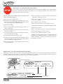
PLEASE INSPECT ALL PACKAGING PRIOR TO DISCARDING!
Your Casablanca fan was crafted with pride and care and inspected thoroughly prior to shipment. Before
you begin to assemble and install your Casablanca fan, remove all parts from the carton and check them
against the Parts Guide in this manual.
Make sure all parts are included in the box using the Parts
Guide on the following pages.
If there are missing or broken parts:
Call 1-888-227-2178 Monday through Friday, 7 a.m. to 4 p.m. PST. Your request will be handled immediately. Replacement
parts will be sent to you via Federal Express.
Proper Parts Handling
Do not remove lightbulbs from their packaging until you are
ready to install them. Before discarding packaging materials, be certain that all parts
have been removed. Use a clean, dry paintbrush to remove small Styrofoam pieces
that may remain after unpacking.
Do not brush Styrofoam into wiring cavities. The blades in each pack are matched for equal weight to assure
smooth fan operation. If more than one fan is being installed,
do not mix blades from different cartons. Always turn power to the ceiling fan OFF before replacing
lightbulbs or working on your fan. Never insert anything into the path of the fan blades while
the fan is in operation. Never install a fan over a pool or spa. Never operate a fan that has been damaged in any way. Install the fan according to the instructions in this manual.
If the fan does not work:
Refer to the Troubleshooting Tips in this Owner’s Manual.
Call Technical Support at 1-888-227-2178.
Contact your local Authorized Service Center.
Our Web site at www.casablancafanco.com contains additional
information on Casablanca products, troubleshooting, and
Authorized Dealer or Service Centers. Please do not return
this product to the store.
When cleaning, painting, or working near your fan, be cautious
of the fan and blades.
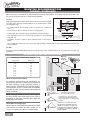
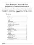
RECORD MODEL AND SERIAL NUMBERS BEFORE INSTALLATION!
Please take a moment to locate the model number and serial number from your fan (see below) and record this information on
the Warranty page inside the front cover of your Owner’s Manual if it does not appear there already. These numbers are found on
the motor identification plate affixed to the fan motor in the location shown below:
Motor Identification Plate
Holliston™ DC
TYPEHANGER TYPE
POMONA, CA
SERIAL No.: DJ06 2237
C31UxxB
2
DJ01 1151 MODEL #C31UxxB
Serial Number
Model Number
Holliston™DC
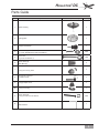
Parts Guide
Item #
Description
Picture (not to scale)
Quantity
1.
Motor Housing
1
2.
Ceiling plate
1
3.
Phillips Screwdriver
1
4.
Screw Pack (A):
1" x 8-32" Roundhead screws and Washers
2 EA
5.
Screw Pack:
Lag Screw and Washer (1)
1 EA
6.
Screw Pack (A):
Wire Nuts (4),
4
7.
Canopy and Canopy Hatch
1
8.
Perma•Lock™ Downrod
and Ball Assembly
1
9.
Hanging Adapter Cover
1
Canopy Cover Ring
1
10.
11.
12.
Screw Pack (B):
Canopy Screws and Lock Washers,
Allen Wrench
4 EA
1
3
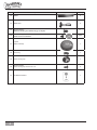
Item #
Description
Picture (not to scale)
Quantity
13.
Blades
5
14.
Blade Irons
5
15.
Screw Pack (C):
16.
Screw Pack (D):
Blade Screws and Washers
Blade Iron Screws (pre-installed, see pg 13, step 9a)
11
16 EA
17.
Light Kit
Adaptor Assembly
1
18.
Screw Plug
1
19.
Switch Housing Cap
1
20
21
4
Screw Pack (E):
2
DC Remote Control
1
Switch Housing Cap Screws 8-32 x 3/8
Holliston™DC
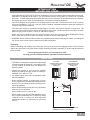
Introduction
Before You Start
• CAUTION: RISK OF ELECTRICAL SHOCK! Installation is to be in accordance with the National Electrical Code,
ANSI/NFPA 70-1999 and local codes. If you are unfamiliar with the wiring codes, you should use a qualified
electrician. To avoid overheating and possible damage to other equipment, do not install control to a receptacle,
fluorescent light fixture, motor-operated appliance, or transformer-supplied appliance.
• This fan is designed to be installed on an existing electrical outlet box. The outlet box must be UL Listed for
ceiling fan installations. If it is not, a new box must be installed. Casablanca extension poles are available for
sloped or high ceiling installations.
• This ceiling fan requires a grounded electrical supply of 120 VAC, 60 Hz and a minimum 15 amp circuit. The
maximum current requirement for the fan with light fixture is 3.0 amps. The fan uses about 0.4 amps or 38 watts.
Maximum light current is about 1.6 amps or 190 watts of lighting.
• Where wire nuts are employed, be sure all bare wires are within the connectors. When installing the canopy
hatch, make sure all wires are within the canopy and that no wires are being pinched.
• WARNING: Do not bend the blade brackets when installing the brackets, balancing the blades, or cleaning the
fan. Do not insert foreign objects in between the rotating fan blades.
Unpacking
Before assembling and installing your ceiling fan, remove all parts from the shipping cartons and check them
against the parts listed in the Parts Guide. Before discarding packaging materials, be certain that all parts have
been removed.
For best performance and for your warranty to be valid,
use only genuine Casablanca blades, light fixtures, and accessories.
Safe Use
• The blades in each pack are matched for equal weight
to assure smooth fan operation. If more than one fan
is being installed, be careful not to mix blades from
different cartons.
Fuse Box
(Remove fuse for the
circuit you will be
working on)
Circuit Breaker
(Trip breaker for the
circuit you will be
working on)
• Inspect the contents of your carton for possible
shipping or handling damage. If parts are missing or
damaged, call 1-888-227-2178.
• It is always a good idea to have an assistant to help
with the installation.
• When cleaning, painting, or working near your fan,
be very careful of the fan and blades. Always turn the
power OFF to the ceiling fan before working on it or
replacing lightbulbs.
• Never insert anything into the path of the fan blades
while the fan is in operation.
• Never install a fan over a pool or spa.
• Never operate a fan that has been damaged in any
way. Contact Casablanca Fan Company by calling
1-888-227-2178, or contact your local authorized
Casablanca dealer for assistance in obtaining
service.
18"
78"
84"
Dimensions indicated are the minimum
allowable for proper installation.
5
MOUNTING RECOMMENDATIONS
General Guidelines
Before mounting your Casablanca fan, read the following helpful recommendations. The location of the fan, air circulation, and
fan size are all important factors to consider before installation.
Location
Ceiling fans have practical uses in almost every room in your home. We suggest
you follow these mounting recommendations as you decide where to install
your Casablanca fan.
• For safety reasons, the fan blades must be a minimum of 7' above the
floor.
• Do not locate the fan in a doorway or above a swinging door.
• In bedrooms, fans work best when mounted above the foot of the bed.
• Over pool tables, be sure to provide plenty of clearance to avoid damage
from pool cues.
• In kitchens, be sure to allow for open cupboard doors to clear the fan
blades.
• Do not install a fan close to or over a pool or spa. High humidity combined with corrosive gases will destroy the finish and
warp the blades.
Fan Size
Variable fan speed capability permits the use of a full-size 52" fan even in smaller rooms. For very large rooms, two fans may
be needed.
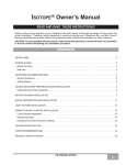
sloped ceiling installations
Suggested Extension Pole Lengths
Ceiling Height
8' 0"
8' 6"
9' 0"
9' 6"
10' 0"
11' 0"
12' 0"
13' 0"
14' 0"
Pole Length
Extension
Pole
3.5"
3.5"
12"
12"
18"
24"
36"
48"
60"
Maximum
Hang-Tru®
angle 32º
Blades must be a
minimum of 7 feet
above the floor
7' minimum
When to Use Extension Poles
For optimum performance and appearance, an
extension pole should be used with your Casablanca
fan when installing on high (cathedral) ceilings or
sloped ceilings. Casablanca offers standard poles in
increments of 6" up to 5'. Custom poles are available
in lengths up to 9'9". See your Authorized Casablanca
Dealer for details.
Note: Fan may wobble or vibrate if pole length is
not long enough and inside blade is too close to
downslope or side wall. Extending pole length will
usually solve the problem.
EXAMPLE 1
EXAMPLE 2
Calculation of Ceiling Angle
Use the tear-off Ceiling Angle Template card inserted
in this manual. It provides you with a simple “go” or
“no-go” for installing your fan on a sloped ceiling.
6
EXAMPLE 3
This slope is less than 32º.
It is OK to install your fan.
This slope is 32º. This is the maximum slope that will allow the fan to
hang straight down. It is OK to install
your fan.
This slope is more than 32º. Your
fan will not hang straight down; an
adapter is necessary. Contact your
local Authorized Casablanca Dealer
in regards to purchasing a “Sloped
Ceiling Adapter.”
Holliston™DC
Fan Installation
Getting Started
Installing a New Ceiling Fixture Outlet Box
Using Existing Ceiling Fixture Outlet Box
If you do not have an existing fixture located where
you wish to place your Casablanca fan, an approved
ceiling fixture outlet box must be installed and wired.
After turning the power OFF at its source (either the
circuit breaker or fuse box), lower the old fixture and
disconnect the wiring. Check the ceiling fixture outlet
box to be sure it is marked “Approved for Ceiling Fan
Mounting.” If it is not, a new box must be installed.
warning!
To reduce the risk of fire, electrical shock,
or personal injury, mount to outlet box
marked “Acceptable Fan Support of 22.7
kg (50 lbs.) or less” using the mounting
hardware provided with the outlet box.
Note: The weight of this fan is 26 pounds.
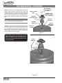
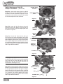
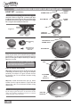
Ceiling plate Installation
Ceiling Hardware (not to scale)
Ceiling Plate
Screw Pack:
Lag Screw and Washer (1)
1" x 8-32 Roundhead Screw and Washer (2)
Note: After removing the old fixture, check the outlet
box to ensure that it is supported by a joist or beam
across its upper surface. If not, a 2 x 4 stud must be
installed.
Step 1a. Remove the knockout plug in the center of
the outlet box or drill a 1/2-inch hole for the lag screw
to pass through. Then drill a 1/4-inch guide hole into
the joist or beam to a depth of 3 inches.
Step 1b. Route the outlet box wires through the hole
of the ceiling plate as shown. Attach the ceiling plate
to the outlet box with the screws provided, making sure
the outlet box wires are not being pinched.
Wire Nut (4)
JOIST
CEILING FANAPPROVED
WIRING BOX
CEILING
PLATE
CEILING
WIRING
CAUTION:
To reduce the risk of personal injury, use
only the mounting hardware provided
with the approved outlet box to install the
ceiling plate.
Outlet Box
Hardware
WASHERS
7
Lag Screw Installation
NOTE: This step is required only under two conditions:
If the fan weighs 36 lbs. or more or if the existing ceiling
fixture outlet box needs to be modified for a ceiling
fan application (for example, if the house is not new
construction and you are replacing an existing light
fixture). We recommend that the ceiling box be of
sufficient capacity to support the weight of the fan and
light fixture under any conditions. If in doubt whether
you need to install the lag screw, consult a qualified
electrician.
Step 2. With the large washer attached, pass the lag
screw through the center hole of the ceiling plate and
screw into the guide hole. Tighten until the outlet box is
mounted firmly to the beam. This box must be secured
to the ceiling firmly.
Canopy Installation
Canopy Hardware (not to scale)
Canopy Hatch
Canopy
Canopy Screws and (4) Lock Washers
Phillips
Screwdriver
Step 3. Attach the canopy to the ceiling plate with
three of the 8-32 x 21/2" long canopy screws and lock
washers provided with your Casablanca fan. Tighten
using the provided screwdriver until snug against
the ceiling.
NOTE: On sloped ceilings, align the canopy opening
with the top or peak of the room.
CANOPY
LOCK WASHERS
CANOPY SCREWS
8
Holliston™DC
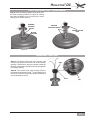
Fan Preparation
Perma•Lock™ Hardware (not to scale)
Perma•Lock™ Downrod
and Ball Assembly
Hanging Adapter Cover
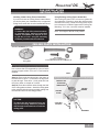
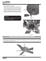
IMPORTANT SAFETY INFORMATION:
Before starting the installation of your
ceiling fan, install the threaded downrod into
the motor coupling and lock the assembly.
Canopy Cover
Ring
Allen Wrench
PAPER MOTOR
SHIELD
Figure #1
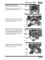
Prepare for fan installation as follows:
Step 4a. Remove the paper shield from the motor as
shown in Figure #1.
Step 4b. Using the provided Allen wrench (attached
to the paper motor shield), loosen the Allen set screw
making sure that end of the Set Screw can not be
seen within the motor coupling as shown in (Figure
#2). If so, you will need to unscrew the Set Screw so
that the tip of the Set Screw does not remain in the
path of the downrod as shown in (Figure #3).
CAUTION: Failure to fully lock in the
downrod before securely tightening the
Allen set screw may cause the fan to
separate from the downrod and fall during
normal operation.
Figure #2
Figure #3
9
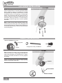
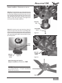
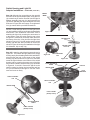
Fan Preparation - continued
Step 4c. Slide both the hanging adapter cover and
canopy cover ring on to the pole, then route the
wires through the 3.5" Perma•Lock downrod and ball
assembly as shown in Figures #4. Insert the downrod
into the motor coupling and turn it clockwise until it
stops turning, ensuring that the pole has bottomed
out.
Tip: The downrod has a tapered thread that is designed
to lock completely when installed correctly.
Step 4d. Tighten the set screw with the Allen wrench
as shown in Figure #5 to ensure safe operation of your
fan. If it is tight enough, you should not be able to turn
the downrod counterclockwise with your hands. If in
doubt, tighten the set screw with the Allen wrench
until you cannot turn it any further.
CANOPY COVER
RING
MOTOR WIRES
(LEAVE AT LEAST
6" LONG)
PERMA•LOCK™
DOWNROD AND
BALL ASSEMBLY
HANGING
ADAPTER COVER
MOTOR
COUPLING
TAPERED
THREAD
MOTOR
HOUSING
ASSEMBLY
ALLEN SET
SCREW
Figure #4
CAUTION: Failure to fully lock in the
downrod before securely tightening the
Allen set screw may cause the fan to
separate from the downrod and fall during
normal operation.
ALLEN
WRENCH
ALLEN SET
SCREW
Figure #5
10
Holliston™DC
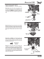
Fan Preparation - continued
Step 4e. Slide the hanging adapter cover down over
the motor coupling as shown in Figure #6, making
sure that the adapter cover is covering the motor
coupling as in shown Figure #7.
HANGING
ADAPTER
COVER
HANGING
ADAPTER COVER
CANOPY COVER
RING
MOTOR
COUPLING
Figure #7
Figure #6
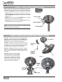
Hanging the Fan
Step 6a. To hang the fan body in the canopy, hold
the fan body firmly and insert the ball into the canopy
opening. Check that no wires are pinched. Rotate the
fan body until the slot in the ball fits into the pin opposite
the canopy opening.
BALL
Step 6b. Trim excess motor wires, leaving at least 6
inches above the downrod. Strip 1/2-inch insulation from
the end of each wire using a wire stripper (available at
your local hardware store).
SLOT
PIN
11
Canopy Electrical Connections
Step 7. Attach the fan wires to the ceiling fixture outlet box
wiring by placing the bare ends of the wires side by side
and then securing with a wire nut. Test that the connection
is secure by pulling on the wire nut. Connect in this order:
WIRE NUT
• GREEN leads from mounting plate and downrod assembly
of fan to GROUND conductor of power source. Secure
with wire nut.
2 BLACK WIRES
• WHITE wire from fan to white NEUTRAL wire in ceiling
fixture outlet box. Secure with wire nut.
• BLACK power wire from fan to BLACK power wire in
ceiling outlet box. Secure with wire nut.
2 WHITE WIRES
NOTE: If the color of your ceiling wires differs from that
described, consult an electrician.
3 GREEN WIRES
Canopy Hatch and cover ring Installation
Step 8a. Tuck the wires into the canopy with the
wire nuts pointed upwards, so that the WHITE and
BLACK wires are on opposite sides of the canopy
and all wires are clear of the canopy opening.
Step 8b. Install the canopy hatch with the last
canopy screw and lock washer using the provided
screwdriver. To do this, tilt the fan body away from
the hatch opening. Tighten the screws firmly.
Step 8c. Straighten the fan, then check to ensure
there is no movement between the canopy and the
ceiling or the Perma•Lock™ downrod and the ball
assembly.
Step 8d. Locate the locking pins
on the canopy cover ring as shown
in Figure #2. Lift up on the canopy
cover ring and guide the two (2)
locking pins into the two (2) locking
holes, then snap the canopy cover in
to place as shown in Figure #3.
CANOPY
CANOPY
HATCH
CANOPY
SCREW &
WASHER
Figure #1
CANOPY
COVER
RING
LOCKING
HOLES
LOCKING PINS
Figure #2
12
Figure #3
Holliston™DC
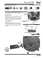
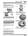
Blade Installation
Blade Hardware (not to scale)
Blades (5)
Blade Irons (5)
Blade Iron
Screws
Step 9a. Remove the five shipping blocks, and
screws as shown in Figure #2. DO NOT discard the
ten (10) screws; you will need them for installing the
blades onto the fan.
Attach Blade Irons
Step 9B. Attach a blade to a blade iron by first
pressing the blade iron onto the blade, then attaching
the blade iron using three blade screws and blade
washers as shown in Figure #3. Using the provided
screwdriver, tighten securely by hand only. Repeat
for each blade assembly.
Blade Installation
Washers (16)
Phillips
Screwdriver
Blade Screws (16)
SHIPPING
BLOCKS
SHIPPING BLOCKS
SCREWS
Step 9c. Before attempting to attach the blades,
review Figure #4 for blade placement on the motor.
The numbers and lines show screw placement when
attaching the five blade irons and blades assemblies
to the fan.
Figure #2
BLADE IRON
SCREWS
BLADE WASHER
BLADE
BLADE IRON
Figure #3
BLADE AND
BLADE HOLDER
Figure #4
13
Blade Installation Continued
Step 10b. Attach a blade/blade iron assembly to the
motor by using two blade iron screws provided. Place
the end of the blade iron on the motor as shown in
Figure #5. Insert the screws one by one using the
provided screwdriver. Tighten securely by hand only.
Repeat for each blade/blade iron assembly until all five
blades are attached to the fan as shown in Figure #6.
MOTOR
Caution:
Blade screws must be tightened securely
before operating the fan.
Figure #5
Figure #6
LIGHT FIXTURE Installation (optional)
NOTE: If you are installing your fan without a light kit attached as below in Figure #1, continue with these installation
instruction Step 11a. If you have purchased a light kit for installation on your fan, skip this section and go to Step
13a on page 18 within this document.
Figure #1
14
Holliston™DC
switch housing and end cap Installation
NO LIGHT KIT - Installation:
SCREW
#6-32
SCREW PLUG
NOTE: If you are installing your fan without a light
kit attached as shown in Figure #1, continue with these
installation instruction
BOTTOM CAP
SCREW
#6-32
CAP
Figure #1
LIGHT KIT
PLATE
Switch Housing Hardware (not to scale)
Screw Plug
Figure #2
BOTTOM CAP
SCREW , #6-32
Light Kit Adaptor Assembly
Step 11a. Locate the light kit adaptor assembly and
screw plug as shown in the switch housing hardware
section above. You will need to install the complete
assembly for no light kit installation.
BOTTOM CAP
Figure #3
NOTE: Do not discard screws during
disassembly, all screws will be needed
for other installation steps within this
document.
CAP
Light Kit Adaptor Disassembly
Step 11b. Locate and remove the one #6-32
screw that is attaching the bottom cap to the light
kit adaptor assembly as shown in Figure #2 and
remove the bottom cap. Do not discard screws during
disassembly.
Cap SCREW,
#6-32
Figure #4
Step 11c. Locate and remove the four #6-32 screws
from the cap and remove the cap. Do not discard the
screws during disassembly.
NOTE: Locate the light kit adaptor as shown in Figure #2,
this adaptor plate will need to be attached to the fan during
fan installation for light kit or no light kit installation.
15
Switch Housing and Light Kit
Adaptor Installation: - ( NO LIGHT KIT)
Step 12a. Locate and remove the three #8-32
screws from the center shaft adapter located on
the bottom of the fan as shown in Figure #1. Do not
discard the screws, all three screws will be needed
for the next steps with in this document.
CENTER SHAFT
ADAPTER
ADAPTER SCREWS
, #8-32
Figure #1
Step 12b. Locate the light kit adaptor plate and
thread the BLUE and WHITE wires through the
hole in the center of the light kit adaptor plate, also
as shown in Figure #2.
LIGHT KIT
ADAPTOR
PLATE
WHITE
WIRE
Step 12c. Locate the three screws that you
removed from the center shaft adapter during Step
12a. These three screws are needed to attached the
light kit adaptor plate to the fan. Align the screw hole
on the light kit adaptor plate with the screw holes on
the center shaft adaptor and insert all three screws
as shown in Figure #3. Then tighten all three screws
with the provided screwdriver.
Figure #2
BLUE
WIRE
CENTER SHAFT
ADAPTER
LIGHT KIT
ADAPTOR
PLATE
SCREWS , #8-32
Figure #3
NOTE: Make sure that the wire nuts on the ends of
the WHITE and BLUE wires are securely attached
to the ends of the wires and that the wires are
tucked out of the way so that the wires are not
pinched when attaching the cap.
Step 12d. Locate the light kit adaptor plate cap as
shown in Figure #4 and align the four screw holes
on the cap with the holes on the light kit adaptor
plate. Using the four (4) screws that you removed
earlier from the light kit adaptor assembly (see step
11c), insert the four screws, attaching the cap to
the bottom of the fan. Then tighten all four screws
with the provided screwdriver.
WIRE NUTS
(WHITE and BLUE)
WIRES
CAP
SCREWS, #6-32
Figure #4
16
LIGHT KIT
ADAPTOR
PLATE
Holliston™DC
Switch Housing and Light Kit
Adaptor Installation - Continued ( NO LIGHT KIT)
Step 12e. Locate the bottom cap and screw as shown
in Figure #5, using the screw that you earlier removed
from the light kit adaptor assembly (see step 11c) and
insert cap screw through the hole in the center of the
cap and attaching the cap the bottom of the fan as
shown in Figure #5 on this page. Then tighten the
screw with the provided screwdriver.
BOTTOM
CAP
Step 12f. Locate the end cap screw plug shown in
Figure #6, align and insert the two (2) holding tabs
located on the screw plug with the slots located in the
center of the end cap, then press on the plug locking
end cap screw plug into place also as shown in Figure
#6 and Figure #7.
CAP SCREW
#6-32
Figure #5
PLUG
TABS
END CAP
SCREW
PLUG
Figure #6
END CAP
SCREW
PLUG
Figure #7
Switch Housing and Light Kit
Adaptor Installation ( NO LIGHT KIT ) - END
NOTE: To continue installation instruction,
go to (Inteli-Touch 3 - Control Installation)
within this document. Figure #8
17
switch housing and end cap Installation
LIGHT KIT - Installation:
SCREW
#6-32
SCREW PLUG
NOTE: If you are installing your fan with a light kit
attached as below in Figure #1, continue with these
installation instruction Step 13a. Also you will need the
installation instructions that came with your new light
kit to complete the installation of the fan.
BOTTOM CAP
SCREW
#6-32
CAP
Figure #1
LIGHT KIT
ADAPTOR
Figure #2
Switch Housing Hardware (not to scale)
Switch Housing
Cap
Light Kit
Adaptor Assembly
Switch Housing
Cap Screw (2)
8-32 x 3/8
BOTTOM CAP
SCREW , #8-32
BOTTOM CAP
Step 13a. Locate the light kit adaptor assembly and
screw plug as shown in the switch housing hardware
section above. You will need to disassemble and use
parts from the light kit adaptor assembly for adding a
light kit to your fan.
Do not discard screws during disassembly,
all screws will be needed for other installation
steps within this document.
Figure #3
CAP
Light Kit Adaptor Disassembly
Step 13b. Locate and remove the #6-32 screw that
is attaching the bottom cap to the light kit adaptor
assembly as shown in Figure #3 and remove
the bottom cap. Do not discard screws during
disassembly.
Cap SCREW,
#6-32
(Screws 4)
Figure #4
Step 13c. Locate and remove the four (4) #6-32
screws from the cap as shown in Figure #4 and
remove the cap. Do not discard screws during
disassembly.
NOTE: Locate the light kit adaptor as shown in Figure
#5, this adaptor plate will need to be attached to the fan
during fan installation, installation instructions continued
on the next page of this document.
LIGHT KIT
ADAPTOR
Figure #5
18
Holliston™DC
Switch Housing and Light Kit
Adaptor Installation: - Continued ( LIGHT KIT)
Step 14a. Locate and remove the three (3) #8-32
screws from the center shaft adapter located on the
bottom of the fan as shown in Figure #6.
CENTER SHAFT
ADAPTER
ADAPTER SCREWS,
#8-32
(Screws 3)
Figure #6
Step 14b. Locate the light kit adaptor plate as shown
in Figure #7 and thread BLUE and WHITE wires
through the hole in the center of the light kit adaptor
plate, also as shown in Figure #7.
LIGHT KIT
ADAPTOR
PLATE
WHITE
WIRE
Figure #7
Step 14c. Locate the three (3) screws that you
removed from the center shaft adapter during Step
14a, these three screws are needed to attached the
light kit adaptor plate to the fan. Align the screw hole
on the light kit adaptor plate with the screw holes on
the center shaft adaptor and insert all three (3) screws
as shown in Figure #8. Then tighten all three screws
with the provided screwdriver.
BLUE
WIRE
CENTER SHAFT
ADAPTER
LIGHT KIT
ADAPTOR
PLATE
SCREWS , #8-32
(Screws 3)
Figure #8
Step 14d. Locate the light kit adaptor plate cap as
shown in Figure #9 and thread BLUE and WHITE
wires through the hole in the center of the light kit
cap, also as shown in Figure #9
CAP
WHITE
WIRE
BLUE
WIRE
Figure #9
19
Switch Housing and Light Kit
Adaptor Installation: - Continued ( LIGHT KIT)
Step 14e. Align the four screw holes on the cap with
the holes on the light kit adaptor plate, using the four
(4) screws that you earlier removed from the light kit
adaptor assembly (see step 11c) and insert the four
(4) screws, attaching the cap to the bottom of the fan
as shown in Figure #10 on this page. Then tighten all
four (4) screws with the provided screwdriver.
NOTE: Locate and open the box for the light kit that
you are installing on the fan and locate the installation
instructions. If the installation instructions refer to
attaching the light kit by screwing the center stem in
to the bottom of the fan, switch housing cap or that
the light kit is mounted by screw the center stem into
the bottom of the fan, it may look like the light kit as
shown in Figure # 12. You will need to use the switch
housing cap that has been provided in the box as
shown in Figure #11 during the installation of the light
kit. Otherwise, skip to step 14g.
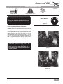
Step 14f. Locate the switch housing cap as shown in
Figure #11. Then attach the light fixture to the switch
housing cap by first threading the BLACK and WHITE
wires through the hole in the center of the switch
housing cap, also as shown in Figure #13, and then
screw the light kit fixture to the bottom of the switch
housing cap by screwing the center stem of the light
fixture into the bottom switch housing cap as shown
in Figures # 13 and #14. Secure the light kit to the
switch housing by placing the lock washer and hex
nut you removed from the light kit onto the center
stem and screw on firmly.
WHITE
WIRE
Figure #10
CENTER STEM
CENTER STEM
LIGHT KIT
Figure #11
SWITCH HOUSING
CAP
Figure #12
BLACK AND WHITE
WIRES
HEX NUT
CENTER STEM
LOCK
WASHER
SWITCH HOUSING
CAP
SWITCH HOUSING
CAP
CENTER STEM
LIGHT FIXTURE
{Example Photo}
BLACK AND WHITE
WIRES
LIGHT FIXTURE
{Example Photo}
Figure #13
Figure #14
Holliston™DC
Switch Housing and Light Kit
Adaptor Installation: - Continued ( LIGHT KIT)
Step 14g. Connect the wires of the motor to the
wires of the light fixture. Connect the BLUE wire from
the motor to the BLACK wire of the light fixture and
connect the two WHITE wires together, as shown in
Figure #15. Secure the connection using the wire
nuts.
BLUE AND
WHITE WIRES
WIRE NUT
BLACK AND WHITE
WIRES
LIGHT FIXTURE
{Example Photo}
Step 14h. Align the two (2) posts on the light kit
assembly and the two (2) holes located on the switch
housing cap as shown in Figure #16 and insert the
posts on the light kit assembly into the two (2) holes
on the light kit adaptor plate cap as shown in Figure
#16.
Figure #15
TWO (2)
SCREWS
HOLES
TWO (2)
SCREW
HOLES
TWO (2)
POST
Figure #16
Step 14h. Locate the two (2) switch housing cap
screws as shown in Figure #17. Then attach the light
fixture to the switch housing on the bottom of the fan
as shown in Figure #17 and tighten the screws with
the provided screw driver.
Switch Housing
Cap Screw (2)
8-32 x 3/8
Step 15i. At this time locate and continue the
installation of the light kit by using the installation
instructions that were provided within the box with the
light kit. Once the light kit has been installed return to
the next section (WALL CONTROL PREPARATION)
of this document. You will need to install the wall
control (W-84) and learn how to operate the fan and
light on the Holliston fan.
SWITCH HOUSING
Switch Housing
Cap Screw (2)
8-32 x 3/8
LIGHT FIXTURE
{Example Photo}
Figure #17
21
DC Control
Control Installation and Operation
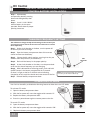
Control Battery Installation
Step 1. Open battery
compartment door by pressing
down and sliding battery door
down.
Step 2. Install 1 "A23" "MN21"
alkaline battery in the space
provided. Please observe proper
polarity placement.
-
+
Changing frequency setting
You will have to change the dip switch settings in the remote if you
are using more than one fan in the same area and want to control
them separately.
Step 1. At the circuit breaker or fusebox, turn the power off
for the fan you want to change.
Step 2. Open the battery compartment door of the remote
control and remove the battery.
ON
1
ECE
2
3
4
Step 3. Change the dip switch settings, assuring that they are
different from the previously installed fan(s).
Set
Button
Step 4. Re-install the battery in the proper polarity.
D
Step 6. Within 60 seconds of restoring power, push and hold
the SET button in the battery compartment for 5 seconds.
(If there is a light on the fan it will flash twice indicating
completion of this step) You should now have control of the fan.
ON
Step 5. At the circuit breaker or fuse box, turn the power back
on for the fan whose frequency you are changing.
ON
1
2
ECE
3
SET
4
Note: You may want to label your controls
to assure you do not mix them up.
Step 7. Reinstall battery compartment door.
Operation CFL Mode
Your fan has the ability to disable the dimming feature to allow the use of CFL bulbs.
ON
D
To activate CFL mode:
1. Open the battery compartment door.
Caution: CFL
bulbs will
not function
properly when
dimmed,
which may
result in
flickering or
reduced bulb
life.
2. With the fan power off, move the toggle switch towards "D".
3. Replace the battery compartment door.
4. Press the power button again to restore power to the fan.
7. Replace the battery compartment door.
22
D
6. With the fan power off, move the toggle switch towards "ON".
ON
To cancel CFL mode:
5. Open the battery compartment door.
ON
1
2
ECE
3
4
SET
DC Control
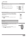
Control Holster Installation
Step 1. Locate a 2x4 wall stud in a convenient
location.
Step 1. Orient the control bracket as shown over
the 2x4 stud.
Step 1. Use the provided screws in the mounting
holes. Install and tighten screws by hand only.
Operation Speed Control
There are six individual speed settings for the fan. Each speed is
indicated by the number on the controller. To properly calibrate all
speeds of the motor, run the fan on speed "6" for 90 seconds after
each AC power reset.
To select the desired fan speed:
Press the number on the controller corresponding to the speed
desired. is off.
Note: It is normal for the fan to start in the "High" position from "Off " before changing to
the selected speed.
Operation Reversing Airflow
The direction of airflow can be changed from downward to upward
or from upward to downward.
To reverse the airflow:
1. Make sure the fan is on and blades are turning.
2. Press the
reverse button. The fan will stop and teeter back
and forth and then change directions.
23
DC Control
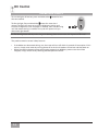
Operation Lights
To turn the lights off and on, press and release the
than one second.
button for less
To dim the light, Press and hold the button for more than 1
second. The light will come on at the last brightness setting and
increase in brightness until full power is reached, then start dimming
until the lowest setting is reached. This cycle will repeat until you
release the light button.
Note: The dimming feature will only work as long as the dimming feature remains active. See "Operation CFL mode".
The product contains several safety features:
•
•
If the blades are obstructed during use, the motor will turn off within 3 seconds of interruption. If this
occurs, simply reset motor by turning power off at the circuit breaker of fuse box and then back on.
When the receiver detects power consumption greater than 80 Watts, power to the fan will be
stopped, simply restart fan by selecting desired speed on control.
24
Holliston™DC
Troubleshooting tips
Please refer to this troubleshooting guide before requesting service or contacting your dealer for assistance.
PROBLEM
POSSIBLE REMEDIES
Fan will not start
• Check the main circuit fuses, circuit breakers, and wall switch position.
Check all wire connections. Make sure the power is turned off during
this inspection.
• Pin connectors are not making good contact. Check all connections.
• The fan receiver is defective. Replace the fan receiver.
• Reset the frequency setting: Turn the power off at the circuit breaker
for the fan that is not functioning only. Within 60 seconds of restoring
power, push and hold the SET button in the battery compartment for
5 seconds. You should now have control of the fan.
• Be sure the canopy pin is set properly into the slot on the ball.
• Check that the blade holders have not been bent during installation
and the blades are balanced.
• The hanger bracket and/or the ceiling outlet are attached too loosely.
Make sure the hanger bracket is attached tightly to the ceiling outlet
box and the downrod assembly is secured firmly.
• The downrod is attached to the downrod base too loosely. Make sure
all the screws are securely tightened.
• When changing fan speeds, you may hear several audible clicks. This
is normal operation.
• Check and tighten the light fixture retaining screws, glass shade screws,
and/or lightbulb(s).
• Tighten the canopy screws and mounting plate assembly. Make sure
the wire nuts inside the canopy and switch housing are not touching the
metal parts and that they have not fallen off the wire splices. Tighten
as necessary.
• Tighten the blade holders to the motor) and the blades to the bladeholder
screws.
• Make sure all the screws in the motor housing are snug but not overly
tight.
Fan wobbles or shakes excessively
Fan is noisy during operation
Fan speeds do not appear correct
• Reset A/C power to the fan and run on speed "6" for at least 90 seconds.
This device complies with RSS-210 of Industry Canada. Operation is subject to the following two conditions: (1) this device
may not cause interference, and (2) this device must accept any interference, including interference that may cause undesired operation of the device.
1. This device complies with part 15 of the FCC Rules. Operation is subject to the following two conditions: (1) this device
may not cause harmful interference, and (2) this device must accept any interference received, including interference that
may cause undesired operation.
2. This equipment has been tested and found to comply with the limits for a Class B digital device, pursuant to Part 15 of
the FCC Rules. These limits are designed to provide reasonable protection against harmful interference in a residential
installation. This equipment generates, uses and can radiate radio frequency energy and, if not installed and used in accordance with the instructions, may cause harmful interference to radio communications. However there is no guarantee
that interference will not occur in a particular installation. If this equipment does cause harmful interference to radio or
television reception, which can be determined by turning the equipment off and on, the user is encouraged to try to correct
the interference by one or more of the following measures: Reorient or relocate the receiving antenna, Increase the separation between the equipment and receiver, Connect the equipment into an outlet on a circuit different from that to which the
receiver is connected. Consult the dealer or an experienced radio/TV technician for help. Note: Any changes or modifications to the transmitter or receiver not expressly approved by Casablanca Fan Company may void one’s authority to operate
this remote control.
25
Care Recommendations
Fan Finishes
• For cleaning, a soft brush or lint-free cloth should be used to prevent scratching the finish.
• A vacuum cleaner brush nozzle can remove heavier dust.
• Surface smudges or an accumulation of dirt and dust can be removed easily using a mild detergent and slightly
dampened soft cloth. An antistatic agent may be used, but never use abrasive cleaning agents as these will
damage the finish.
Blades
• Wood-finish blades should be cleaned with a furniture polishing cloth. Occasionally, a light coat of furniture polish
may be applied for added protection and beauty.
• For painted and high-gloss blades, surface smudges or an accumulation of dirt and dust can be removed easily
using a mild detergent and slightly dampened soft cloth. An antistatic agent may be used, but never use abrasive
cleaning agents as these will damage the finish.
No Need for Lubrication
• Never lubricate this fan! The precision motor at the heart of your Casablanca fan features sealed bearings
that are lubricated for life.
• Do not attempt to oil the motor.
For questions or to locate the nearest Casablanca Authorized Service Center
call toll free: 1-888-227-2178
or visit us on the web at: www.casablancafanco.com
The product contains several safety features:
•
•
If the blades are obstructed during use, the motor will turn off within 3 seconds of interruption. If this
occurs, simply reset motor by turning power off at the circuit breaker of fuse box and then back on.
When the receiver detects power consumption greater than 80 Watts, power to the fan will be
stopped, simply restart fan by selecting desired speed on control.
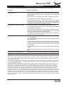
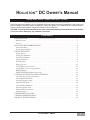
Product Specifications
Model Name:
Holliston
Model Number: C31UxxB
Dimensions:
A =11.7"
B =13.1"
C = 3"
D =13.9"
E = 7"
Weight:
26 lbs.
26
Motor:
DC Motor
Blade Span:
60"
Blade Iron Pitch: 15°
No. of Blades:
5
Technology:
DC Control
Airflow:
7102 cfm
Electricity Use: 32 watts
Airflow Efficiency:222 cfm/watt