1
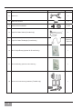
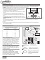
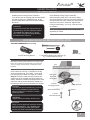
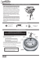
Panama® Owner’s Manual Read and Save These Instructions! Safety and the proper operation of your Casablanca fan both require a thorough knowledge of the product and proper installation; therefore, before attempting to install and operate your Casablanca fan, read this owner’s manual completely and carefully. Retain this manual for future reference. Caution: To avoid possible electrical shock, make certain that electricity is turned off at the circuit breaker or fuse box before attempting any installation procedure. CONTENTS Before You Start���������������������������������������������������������������������������������������������������������������������������������������������������������������������5 Safe Use���������������������������������������������������������������������������������������������������������������������������������������������������������������������������������������5 MOUNTING RECOMMENDATIONS������������������������������������������������������������������������������������������������������������������������������������������������6 SLOPED CEILING INSTALLATIONS����������������������������������������������������������������������������������������������������������������������������������������������6 Getting Started������������������������������������������������������������������������������������������������������������������������������������������������������������������������7 Crossbar Mounting Bracket Installation������������������������������������������������������������������������������������������������������������������� 7 LAG SCREW INSTALLATION (OPTIONAL)����������������������������������������������������������������������������������������������������������������������������������� 8 perma•lock™ hardware�������������������������������������������������������������������������������������������������������������������������������������������������������8 FAN PREPARATION������������������������������������������������������������������������������������������������������������������������������������������������������������������������8 CANOPY HARDWARE��������������������������������������������������������������������������������������������������������������������������������������������������������������������9 CANOPY INSTALLATION���������������������������������������������������������������������������������������������������������������������������������������������������������������9 HANGING THE FAN������������������������������������������������������������������������������������������������������������������������������������������������������������������������9 CANOPY ELECTRICAL CONNECTIONS�������������������������������������������������������������������������������������������������������������������������������������10 CANOPY HATCH INSTALLATION������������������������������������������������������������������������������������������������������������������������������������������������10 BLADE HOLDER & BLADE ASSEMBLY������������������������������������������������������������������������������������������������������������������������������������10 4-SPEED OPERATION������������������������������������������������������������������������������������������������������������������������������������������������������������������ 11 4-SPEED • OPTIONAL LIGHT FIXTURE INSTALLATION����������������������������������������������������������������������������������������������������������� 11 4-SPEED OPTIONAL WALL CONTROL • W-41��������������������������������������������������������������������������������������������������������������������������� 11 4-SPEED • OPTIONAL WALL CONTROL • W-81������������������������������������������������������������������������������������������������������������������������� 11 4-SPEED • W-41 WALL CONTROL OF THE FAN������������������������������������������������������������������������������������������������������������������������ 12 4-SPEED • W-81 WALL CONTROL OF THE FAN & LIGHT(S)���������������������������������������������������������������������������������������������������� 12 Installing the W-85 Wall Control�����������������������������������������������������������������������������������������������������������������������������������15 single W-85 Installation������������������������������������������������������������������������������������������������������������������������������������������������������15 Dual W-85 Installation���������������������������������������������������������������������������������������������������������������������������������������������������������16 Operation Speed Control��������������������������������������������������������������������������������������������������������������������������������������������������17 Operation Reversing Airflow�������������������������������������������������������������������������������������������������������������������������������������������17 Operation lights��������������������������������������������������������������������������������������������������������������������������������������������������������������������17 Operation Power��������������������������������������������������������������������������������������������������������������������������������������������������������������������17 Automatic Demonstration Program������������������������������������������������������������������������������������������������������������������������������18 changing frequency setting��������������������������������������������������������������������������������������������������������������������������������������������18 Operation Home-Safe® Program�������������������������������������������������������������������������������������������������������������������������������������19 Operation Safe-Exit® and light-minder® Program�������������������������������������������������������������������������������������������������� 19 Operation Fan-Minder™ Program������������������������������������������������������������������������������������������������������������������������������������� 20 Troubleshooting tips����������������������������������������������������������������������������������������������������������������������������������������������������������21 P/N 6643Z HN0210 1 PLEASE INSPECT ALL PACKAGING PRIOR TO DISCARDING! Your Casablanca fan was crafted with pride and care and inspected thoroughly prior to shipment. Before you begin to assemble and install your Casablanca fan, remove all parts from the carton and check them against the Parts Guide in this manual. Make sure all parts are included in the box using the Parts Guide on the following pages. If there are missing or broken parts: Call 1-888-227-2178 Monday through Friday, 7 a.m. to 4 p.m. PST. Your request will be handled immediately. Replacement parts will be sent to you via Federal Express. Proper Parts Handling Do not remove lightbulbs from their packaging until you are ready to install them. Before discarding packaging materials, be certain that all parts have been removed. Use a clean, dry paintbrush to remove small Styrofoam pieces that may remain after unpacking. Do not brush Styrofoam into wiring cavities. The blades in each pack are matched for equal weight to assure smooth fan operation. If more than one fan is being installed, do not mix blades from different cartons. When cleaning, painting, or working near your fan, be cautious of the fan and blades. Always turn power to the ceiling fan OFF before replacing lightbulbs or working on your fan. Never insert anything into the path of the fan blades while the fan is in operation. Never install a fan over a pool or spa. Never operate a fan that has been damaged in any way. Install the fan according to the instructions in this manual. If the fan does not work: Refer to the Troubleshooting Tips in this Owner’s Manual. Call Technical Support at 1-888-227-2178. Contact your local Authorized Service Center. Our Web site at www.casablancafanco.com contains additional information on Casablanca products, troubleshooting, and Authorized Dealer or Service Centers. Please do not return this product to the store. RECORD MODEL AND SERIAL NUMBERS BEFORE INSTALLATION! Please take a moment to locate the model number and serial number from your fan (see below) and record this information on the Warranty page inside the front cover of your Owner’s Manual if it does not appear there already. These numbers are found on the motor identification plate affixed to the fan motor in the location shown below: Motor Identification Plate Holliston® TYPEHANGER TYPE POMONA, CA SERIAL No.: DJ06 2237 66xxZ 2 DJ01 1151 MODEL #66xxG/Z or 66DxxG Serial Number Model Number Panama® Parts Guide Item # Description Picture (not to scale) Quantity 1. Motor Housing 1 2. Ceiling plate 1 3. Phillips Screwdriver 1 4. 11/2" x 8-32" Roundhead screws and Washers , 2 EA 5. Screw Pack: Lag Screw and Washer (1) 1 EA 6. Wire Nuts (4), 7. Canopy and Canopy Hatch 8. Perma•Lock™ Downrod and Ball Assembly 9. Canopy Screws and Lock Washers, 10. Allen Wrench 4 1 1 5 EA 1 3 Item # Description Picture (not to scale) Quantity 11. Blade Irons 5 12. Blade Iron Screws 11 13. Blade Screws and Washers 14. Light Pull Chain Switch (G model only) 15. Light Pull Chain Fandangle (G model only) 16. W-41 Single Rotary (optional for G model only) 1 17. W-81 Dual Rotary (optional for G model only) 1 16 EA 1 2 -(66xxG) 3 -(66DxxG) ` 18. 4 W-85 Control and Mounting Hardware (Z model only) 1 Panama® Introduction Before You Start • CAUTION: RISK OF ELECTRICAL SHOCK! Installation is to be in accordance with the National Electrical Code, ANSI/NFPA 70-1999 and local codes. If you are unfamiliar with the wiring codes, you should use a qualified electrician. To avoid overheating and possible damage to other equipment, do not install control to a receptacle, fluorescent light fixture, motor-operated appliance, or transformer-supplied appliance. • This fan is designed to be installed on an existing electrical outlet box. The outlet box must be UL Listed for ceiling fan installations. If it is not, a new box must be installed. Casablanca extension poles are available for sloped or high ceiling installations. • This ceiling fan requires a grounded electrical supply of 120 VAC, 60 Hz and a minimum 15 amp circuit. The maximum current requirement for the fan with light fixture is 3.8 amps. The fan uses about 1 amp or 100 watts. Maximum light current is 2.8 amps or 340 watts of lighting. • Where wire nuts are employed, be sure all bare wires are within the connectors. When installing the canopy hatch, make sure all wires are within the canopy and that no wires are being pinched. • WARNING: Do not bend the blade brackets when installing the brackets, balancing the blades, or cleaning the fan. Do not insert foreign objects in between the rotating fan blades. Unpacking Before assembling and installing your ceiling fan, remove all parts from the shipping cartons and check them against the parts listed in the Parts Guide. Before discarding packaging materials, be certain that all parts have been removed. For best performance and for your warranty to be valid, use only genuine Casablanca blades, light fixtures, and accessories. Safe Use • The blades in each pack are matched for equal weight to assure smooth fan operation. If more than one fan is being installed, be careful not to mix blades from different cartons. • Inspect the contents of your carton for possible shipping or handling damage. If parts are missing or damaged, call 1-888-227-2178. • It is always a good idea to have an assistant to help with the installation. • When cleaning, painting, or working near your fan, be very careful of the fan and blades. Always turn the power OFF to the ceiling fan before working on it or replacing lightbulbs. • Never insert anything into the path of the fan blades while the fan is in operation. • Never install a fan over a pool or spa. • Never operate a fan that has been damaged in any way. Contact Casablanca Fan Company by calling 1-888-227-2178, or contact your local authorized Casablanca dealer for assistance in obtaining service. Fuse Box (Remove fuse for the circuit you will be working on) Circuit Breaker (Trip breaker for the circuit you will be working on) 18" 70" 84" 5 MOUNTING RECOMMENDATIONS Before mounting your Casablanca fan, read the following helpful recommendations. The location of the fan, air circulation, and fan size are all important factors to consider before installation. Location Ceiling fans have practical uses in almost every room in your home. support brace We suggest you follow these mounting recommendations as you decide where to install your Casablanca fan. • For safety reasons, the fan blades must be a minimum of 7' above the floor. standard ceiling outlet • Do not locate the fan in a doorway or above a swinging door. mounting box style • In bedrooms, fans work best when mounted above the foot of the bed. • Over pool tables, be sure to provide plenty of clearance to avoid damage from pool cues. • In kitchens be sure to allow for open cupboard doors to clear the fan blades. • Do not install a fan close to or over a pool or spa. High humidity combined with corrosive gases will destroy the finish and warp the blades. Fan Size Variable fan speed capability permits the use of a full-size 52" fan even in smaller rooms. For very large rooms, two fans may be needed. SLOPED CEILING INSTALLATIONS Suggested Extension Pole Lengths Ceiling Height 8' 0" 8' 6" 9' 0" 9' 6" 10' 0" 11' 0" 12' 0" 13' 0" 14' 0" Pole Length Extension Pole standard standard 6" 12" 12" 18" 24" 36" 48" Blades must be a minimum of 7 feet above the floor 7' minimum When to Use Extension Poles For optimum performance and appearance, an extension pole should be used with your Casablanca fan when installing on high (cathedral) ceilings or sloped ceilings. Casablanca offers standard poles in increments of 6" up to 5'. Custom poles are available in lengths up to 9'9". See your Authorized Casablanca Dealer for details. Note: Fan may wobble or vibrate if pole length is not long enough and inside blade is too close to downslope or side wall. Extending pole length will usually solve problem. Calculation of Ceiling Angle Use the tear-off Ceiling Angle Template card inserted in this manual. It provides you with a simple “go” or “no-go” for installing your fan on a sloped ceiling. 6 Maximum Hang-Tru® angle 32º EXAMPLE 1 EXAMPLE 2 EXAMPLE 3 This slope is less than 32º. It is OK to install your fan. This slope is 32º. This is the maximum slope that will allow the fan to hang straight down. It is OK to install your fan. This slope is more than 32º. Your fan will not hang straight down, an adaptor is necessary. Contact your local Authorized Casablanca Dealer in regards to purchasing a “Sloped Ceiling Adaptor.” Fan Installation Getting Started Installing a New Ceiling Fixture Outlet Box If you do not have an existing fixture located where you wish to place your Casablanca fan, an approved ceiling fixture outlet box must be installed and wired. warning! To reduce the risk of fire, electrical shock, or personal injury, mount to outlet box marked “Acceptable Fan Support of 22.7 kg (50 lbs.) or less” using the mounting hardware provided with the outlet box. Panama® Using Existing Ceiling Fixture Outlet Box After turning the power OFF at its source (either the circuit breaker or fuse box), lower the old fixture and disconnect the wiring. Check the ceiling fixture outlet box to be sure it is marked “Approved for Ceiling Fan Mounting.” If it is not, a new box must be installed. Note: The weight of this fan is 24 to 26 pounds, depending on model. Crossbar Mounting Bracket Installation Ceiling Hardware (not to scale) Crossbar Mounting Bracket Lag Screw and Washer (1) 1" x 8-32 Roundhead Screw and Washer (2) 21/4" x 8-32 Roundhead Screw (2) Note: After removing the old fixture, check the outlet box to insure that it is supported by a joist or beam across its upper surface. If not, a 2 x4 stud must be installed. Step 1a. Remove the knockout plug in the center of the outlet box or drill a 1/2-inch hole for the lag screw to pass through. Then drill a 1/4-inch guide hole into the joist or beam to a depth of 3 inches. Step 1b. Route the outlet box wires through the keyhole slot of the crossbar mounting bracket as shown. Attach the crossbar mounting bracket to the outlet box with the screws provided, making sure the outlet box wires are not pinched by the washer. CAUTION: To reduce the risk of personal injury, use only the mounting hardware provided with the approved outlet box to install the crossbar mounting bracket. warning! Support directly to building structure only. Wire Nut (4) Joist Ceiling-FanApproved Wiring Box Crossbar Mounting Bracket Green Ground Wire Ceiling Wiring Ridge side down Washer 1" x 8-32 Roundhead Screw CAUTION: Damp Location rated fans required a Ground Fault Interrupter(GFI). use a weather-proof outlet box, properly connect ground wires, and use only under a weather-proof structure 7 LAG SCREW INSTALLATION (OPTIONAL) NOTE: This step is required only under two conditions: If the fan weighs 36 lbs. or more (which does not pertain to this fan) or if the existing ceiling fixture outlet box needs to be modified for a ceiling fan application (for example, if the house is not new construction and you are replacing an existing light fixture). We recommend that the ceiling box be of sufficient capacity to support the weight of the fan and light fixture under any conditions. If in doubt whether you need to install the lag screw, consult a qualified electrician. lag screw Step 2 (optional). With the large washer attached, pass the lag screw (Pack A) through the center hole of the crossbar mounting bracket and screw into the guidehole. Tighten until the outlet box is mounted firmly to the beam. This box must be secured to the ceiling firmly. LARGE WASHER perma•lock™ hardware ALLEN SET SCREW 1 ⁄4-20 x 1⁄4” (pre-installed) 1/8" allen wrench downrod & Ball assembly FAN PREPARATION important safety information! before starting the installation of your ceiling fan, install the threaded downrod into the motor coupling and lock the assembly Prepare for fan installation as follows: 3a. Route the wires from the motor through the Perma•Lock™ downrod and ball assembly. Tip: The downrod has a tapered thread that is designed to lock completely when correctly installed. tapered thread ALLEN SET SCREW 3b. Using the provided allen wrench, loosen the set screw several turns to allow installation of the downrod. Thread the downrod into the motor coupling until it stops turning, this will take at least four and a half full turns. 3c. Securely tighten the set screw with the provided allen wrench to ensure safe operation of your fan. CAUTION: Failure to fully lock in the downrod before securely tightening the set screw may cause the fan to separate from the downrod during normal operation! 8 motor coupling motor wires ground wire downrod & Ball assembly Panama® CANOPY HARDWARE CANOPY SCREW (5) CANOPY LOCK WASHER (5) CANOPY HATCH CANOPY CANOPY INSTALLATION Step 4. Attach the canopy to the crossbar mounting bracket with three of the 8-32 x 2 1/2” long canopy screws and lock washers provided with your Casablanca fan. Hand tighten until snug against the ceiling. Note: On sloped ceilings, align the canopy opening toward the top or peak of the room. canopy lock washer FEED OUTLET BOX WIRES THROUGH CANOPY OPENING canopy screw HANGING THE FAN Step 5. To hang the fan body in the canopy, hold the fan body firmly and insert the ball into the canopy opening. Check that no wires were pinched. Rotate the fan body until the slot in the nylon ball fits into the pin opposite the canopy opening. Note: Independent control of the light fixture using a W-81 accessory control requires an additional power wire run from the wall switch to the fan. See Page 12 for wiring. CAPPED BLUE D1-OPTION WIRE (ON 3-SPEED ONLY) FOR LIGHT CONTROL ball slot pin 9 CANOPY ELECTRICAL CONNECTIONS Step 6a. Attach the fan wires to the ceiling fixture outlet box wiring by twisting the bare ends of the wires together and then securing with a wire nut. Test that the connection is secure by pulling on the wire nut. Connect in this order: Step 6b. W-85 Wiring Connections • GREEN leads from mounting plate and fan to GROUND conductor of power source. Secure with wire nut. •WHITE wire from fan to white NEUTRAL wire in ceiling fixture outlet box. Secure with wire nut. • BLACK power wire from fan to BLACK power wire in ceiling outlet box. Secure with wire nut. Step 6c. Pull Chain Connections • GREEN leads from mounting plate and fan to GROUND conductor of power source. Secure with wire nut. •WHITE wire from fan to white NEUTRAL wire in ceiling fixture outlet box. Secure with wire nut. • BLACK power wire from fan to Black wire from W-81 in ceiling outlet box and the BLUE wire form light kit. Secure with wire nut. • BLUE wire from fan to YELLOW wire from W-81 in ceiling outlet box. Secure with wire nut. If you will be installing an accessory light kit, also connect the BLUE light power wire from fan to the BLACK wires). wire nut w-85 connections 2 BLACK 2 WHITE WIRES 3 GREEN WIRES Pull Chain Connections 2 Black + 1 Blue 2 WHITE WIRES 3 GREEN WIRES CANOPY HATCH INSTALLATION Step 7. Tuck the wires into the canopy with the wire nuts pointed upwards, so that the WHITE and BLACK wires are on opposite sides of the canopy and all wires are clear of the canopy opening. Step 8. Install canopy hatch with the last canopy screw and lock washer. To do this, tilt the fan body away from the hatch opening. Tighten the screws firmly by hand only, Step 9. Straighten the fan, then check to ensure that there is no movement between the canopy and ceiling or Hang-Tru ball and top support shaft. 10 canopy hatch lock washer canopy screw tilt the fan to install last canopy screw Panama® blade/blade holder installation Step 10. Attach the blades to the blade holders with the three blade screws and flat washers provided for each blade. Hand tighten securely. Install the assembled blade and blade holder to the fan motor. Hand tighten securely. Repete for each blade assembly. BLADE SCREW (3 PER BLADE) flat washer (3 PER BLADE) BLADE HOLDER SCREW (2 PER BLADE HOLDER) Your fan is equipped with a flywheel that allows for both 4 and 5 blade installation. The screw holes surrounded by squares are for 4 blade installation, while the screw holes in circles are for 5 blade installation as shown above. WARNING: To reduce the risk of personal injury, do not bend blade holders when installing, balancing, or cleaning. Do not insert foreign objects between rotating fan blades. PROCEED TO YOUR FAN’S CONTROL FEATURE SECTION FOR INSTALLATION/OPERATING INSTRUCTIONS: 4-SPEED - PAGE 12 | INTELI•TOUCH3 - PAGE 14 11 4-SPEED OPERATION Pull-chain switches on the fan control the fan and lights. Using the fan control pull-chain switch: Fan off at start. First pull: fan ON, High speed Second pull: Medium speed Third pull: Medium Low speed Fourth pull: Low speed Fifth pull: Fan OFF Using the optional light pull-chain switch: Light off at start. First pull: light ON Second pull: light OFF Direction of blade rotation is controlled by the reverse slide switch on the side of the switch housing. No changes in household wiring are required. OPTIONAL LIGHT PULL CHAIN SWITCH FAN & SPEED CONTROL PULL CHAIN SWITCH REVERSE SWITCH 4-SPEED • OPTIONAL LIGHT FIXTURE INSTALLATION NOTE: If a separate circuit is used to control the lights from a wall control, the BLUE D1-Option wire in the canopy should be connected to that switch leg. 1.Refer to light kit instructions to assemble and attach your light kit correctly. 2.Remove the two 8-32 screws from the switch housing cap. 3.Remove the plug from switch housing. 4. Install pull-chain switch and finger tighten collar on switch. 5. Connect one wire from pull-chain switch to the BLUE D1-Option wire. Secure splice with a wire nut. 6. Connect other wire from pull-chain switch to BLACK wire from light kit. Secure splice with a wire nut. 7. Connect WHITE wire from switch housing to WHITE wire from light kit. Secure splice with a wire nut. 8.At the canopy, connect the BLACK and BLUE wires. SWITCH HOUSING COLLAR white Blue D-1 black light fixture 4-SPEED OPTIONAL WALL CONTROL • W-41 The W-41 wall control provides four-speed control of fan from a convenient wall location. The W-41 is designed to replace a standard wall switch and will fit wall boxes with a depth of 2” or greater. Not for use with single pull-chain fan/light option wiring. To install a W-41 wall control in place of an existing wall switch, follow the instructions on the W-41 package. Note: No rewiring is required if the fan is replacing an existing light fixture. Operation of the fan from the wall switch is simple: 1. Turn knob to obtain desired speed setting. R CAUTION! Failure to set the pull-chain speed to HIGH can result in faulty operation of the fan and damage to the W-41 wall control. To confirm fan is set to HIGH: Turn W-41 fan speed switch to ‘HI’ - set fastest fan speed with pull chain. 4-SPEED • OPTIONAL WALL CONTROL • W-81 The W-81 wall control provides separate control of fan and light with two separate knobs from a convenient wall location. The W-81 is designed to replace a standard wall switch and wall boxes with a depth of 2” or greater. Requires two hot leads from wall box to ceiling wiring box. CAUTION! Failure to set the pull-chain To install a W-81 wall control in place of an existing wall switch, follow the instructions on the W-81 package. speed to HIGH can result in faulty operation of the fan and damage to the W-81 wall Operation of the fan from the wall switch is simple: control. To confirm fan is set to HIGH: Turn 1. Turn the upper knob to the desired fan speed. W-81 fan speed switch to ‘HI’ - set fastest 2. Turn the lower knob to the desired light setting. fan speed with pull chain. 12 LO MED MED HI OFF OFF HI MAX 4-Speed Panama® 4-SPEED • W-41 WALL CONTROL OF THE FAN • The W-41 allows the choice of four (4) different speed settings. • No light fixture is used. • Set the FAN pull chain switch to the HIGH speed setting. • No changes in household or fan wiring are required. • The fan may be turned ON and OFF by the W-41 wall control. CAUTION! Failure to set the pull-chain speed to HIGH can result in faulty operation of the fan and damage to the W-41 wall control. To confirm fan is set to HIGH: Turn W-41 fan speed switch to ‘HI’ - set fastest fan speed with pull chain. R 4-SPEED • W-81 WALL CONTROL OF THE FAN & LIGHT(S) • The fan may be turned ON and OFF by the W-81 wall control. • The lights may be turned ON and OFF by the W-81 and the intensity adjusted from low to high. • The fan must be supplied with two independent 120V AC supply wires. • Set the FAN pull chain switch to the HIGH speed setting. • Turn the lights ON at the fan. • The W-81 allows the choice of four (4) different speed settings. CAUTION! Failure to set the pullchain speed to HIGH can result in faulty operation of the fan and damage to the W-81 wall control. To confirm fan is set to HIGH: Turn W-81 fan speed switch to ‘HI’ - set fastest fan speed with pull chain. 13 ® 3 W-85 Control INSTALLATION WALL CONTROL AND Hardware (not to scale) W-85 Switch Mounting Wall Control Screws (2) Switch Bezels (1) White (1) Almond White Wall Plate(1) Almond Wall Plate(1) Wall Plate Screws (2) White (2) Almond Warning! To avoid possible electrical shock, make certain that electricity is turned off at the circuit breaker or fuse box before attempting any installation or repair procedure (4) Wire Cap BEZEL CAUTION! NOT turning the power OFF at the circuit breaker or fuse box may cause damage to the electronics within the wall control and or the PC board on the fan. BEZEL TABS Before installing the W-85 wall control you will need to check and see if you will need to change the bezel on the front of the wall control from WHITE to ALMOND. If you are going to use white, skip these steps and go to wall control installation starting on page 15. The bezel can be changed at any time before or after installation. The wall control does not need to be uninstalled to replace the bezel. Figure #1 WHITE BEZEL W-85 Wall Control Bezel Replacement installation as follows Step 17a. Locate the four (4) tabs holding the bezel to the front of the switch, then press in on each tab one at a time, removing the bezel as shown in Figure #1. Step 17b. Locate the rubber key pad attached to the four (4) locating pins as shown in Figure #2 and remove rubber key pad from the WHITE bezel, also as shown in Figure #2. 14 LOCATING PINS (4) LOCATING PINS HOLES(4) RUBBER KEY PAD Figure #2 ® 3 W-85 Wall Control Bezel replacement: CONTINUED - ALMOND BEZEL Step 17c. Reinstall the rubber key pad on to the four (4) locating pins located on the almond bezel as shown in Figure #3 and #4. RUBBER KEY PAD Figure #3 Step 17d. To attach the bezel back on to the front of the switch you will need to align the four (4) tabs on the bezel with the front of the wall control and by gently pressing on both top and button of the bezel at the same time, snap the bezel back on to the front of the switch as shown in figure #5. RUBBER KEY PAD ALMOND BEZEL Figure #4 LOCATING PINS (4) ALMOND BEZEL Step 17e. Check your work by pressing on the light, fan, reverse and power buttons, making sure that the buttons do not stick and that each switch functions properly. BEZEL TABS BEZEL ALIGNMENT PIN AND HOLE Figure #5 15 ® 3 W-85 Control INSTALLATION Installing the W-85 Wall Control NOTE: W-85 Wall Control should only be installed on Casablanca's Inteli-Touch® 3 fans with DOWNLIGHTS ONLY. The wall control installs in the same manner as an ordinary light switch, using an existing wall box and wiring. This controller is designed to signal the fan microcomputer as well as perform normal switching operations. For this reason the following precautions must be observed: 3.Do not use more than one fan per wall control. 1.Use only the Casablanca W-85 wall control. 2.Do not use any additional control with your Inteli4.No other light fixtures or electrical appliances Touch 3 fan (for example, dimmer, or fan speed may be connected on the circuit controlled by the control). W-85 wall control. single W-85 Installation CAUTION! Ensure power is turned OFF at the breaker or fuse panel before starting installation. W-85 is used to describe either white (-11) or almond finish. If you have multiple Inteli-Touch 3 fans, refer to the section "Changing Frequency Setting" on page 18. 1.Remove the screws and switch plate from the existing switch box. 2.Remove the screws holding the switch in the switch box. 3.Pull the existing switch from the switch box to expose the wire connections. 4.Remove the two wires from the switch. 5.Connect the BLACK wire from the POWER SOURCE that you just removed from the switch to the BLACK/ NOTE: The RED wire is not used in this application, DO NOT remove the crimped cap from the wire.. WHITE STRIP wire on the W-85 wall control. Secure this connection with a wire nut. 6.Connect the second BLACK wire that you just removed from the switch to the second BLACK wire on the located on the back of the W-85 wall control. Secure this connection with a wire nut. 7.Connect the green ground wire coming from the back of the W-85 control to the ground wire in the switch box. Secure the splice with a wire nut. 8.Check your work by using the wiring diagrams as shown in Figures # 1 and #2. 9. Install the W-85 in the wall box with the two long screws provided. 10. Install the wall plate with the two colormatched screws. 16 W-85 (FIGURE #1) 2 BLACK WIRES W-85 Wall Control RED WIRE NOT USED (FIGURE #2) BLACK AND WHITE STRIPED WIRE ® 3 Dual W-85 Installation To control the fan and lights from two locations (a three-way circuit), use two W-85 wall controls as shown in the wiring diagram in Figure #5. Before installing the two switches into the wall, place both switches side by side, then locate the 4 dip switches on the side of the two switches. Then make sure that the dip switches are set to the same address on both switches as shown in Figure #4. When setting these dip switches you are setting the channel number that is required to control both your fan and lights from both sides of the room. If you are installing other Inteli-Touch® 3 fans within your home you may need to reset the dip switches on these other fans to a different channel before installing your W-85 wall control into the wall. Please review the section on channel changing on this instruction sheet. DIP SWITCHES CAUTION! Ensure power is turned OFF at the breaker or fuse panel before starting installation. (FIGURE #4) NEUTRAL WHITE GREEN BLACK BLACK BLACK WITH WHITE STRIPE W-84 W-85 W-85 W-84 RED BLACK WITH WHITE STRIPE BLACK BLACK RED RED BLACK BLACK RED 120V AC BLACK 2. Pull the existing switch from the switch box to expose the wire connections. GREEN GREEN To control the fan and lights from two locations (a three-way circuit), use two W-85 wall controls. 1. Remove the screws and switch plate from the existing switch box and the screws holding the switch in the switch box. 3. Determine which wire is connected to the common terminal from the power source (120V AC) of the three-way switch. (The terminal will be marked on switch). BLACK 4. Remove the wire from the common terminal of the three-way switch. Connect this wire to the remaining black/white striped wire on the W-85 control. Secure this splice with a wire nut. 2 BLACK WIRES W-85 Wall Control 5.Remove the two remaining wires from the three-way switch. Connect the black wire of these wires to a black wire on the W-85 control. Secure the splice with a wire nut. The remaining red wire is to be connected to the other red wire on the W-85. Secure the splice with a wire nut. 6.Connect the green ground wire coming from the back of the W-85 control to the ground wire in the switch box. Secure the splice with a wire nut. 2 RED WIRES 7.Check your work by using the wiring diagrams as shown in Figure #5 on this page. 8.Install the W-85 in the wall box with the two long screws provided. 9.Install the wall plate with the two short color-matched screws provided. (FIGURE #5) BLACK AND WHITE STRIPED WIRE 10.Installation of the second W-85 control is identical. Repeat steps 1 through 9. 17 ® 3 Operation Power The button is normally left in the on position. Always turn the power off during cleaning or servicing the fan and during thunderstorms. It is also used to exit or enter additional programs. The button must be left on to retain a previously set fan speed or light level. Operation Speed Control There are six individual speed settings for the fan; each speed is indicated by an audible tone of increasing pitch. To select the desired fan speed: 1. With fan off, press and hold the button labeled . The fan blades will start rotating at the slowest speed, and will increase in steps. 2. Release the button when the desired speed is reached. The fan speed is now in memory and will automatically come on at the same speed each time the button is used. To maintain this level of speed, turn the fan on by pressing less than one second. To lower speed, turn fan off, then on by pressing and holding the button until the desired speed is reached. When the fan is on, you may increase the speed by pressing and holding the button until the desired speed is reached, then release it. Fan Control ON - OFF: A momentary press of the FAN button Change speed: Press and hold FAN button longer than one second Operation Reversing Airflow The direction of airflow can be changed from downward to upward or from upward to downward. To reverse the airflow: 1. Make sure the is on and blades are Turning. 2. Press the button. Note: A four-toned signal indicates the command was accepted by the fan. A few seconds later the fan will slow to a stop and then reverse direction. Operation lights To turn the lights off and on, press and release the one second. 1) First press/release of the button for less than button- The light will turn ON. 2) Second press/release of the button- The light will turn OFF. To vary the light brightness at each touch level: To vary the light brightness: 1. With lights off, press and hold the button. After one second the lights will come on at their lowest level and gradually become brighter. NOTE: Light Operation - the light varies from “bright” to “dim” over approximately 8 seconds. This sequence will reverse the light when it reaches the brightest or dimmest level if you continue to hold the LIGHT button. Release the button when the desired level is reached. 2. Release the button when the desired brightness level is reached. The brightness level is now in the fan memory and will automatically come on at the same brightness the next time the button is used. 18 Light Control ON - OFF: A momentary press of the LIGHT button Change brightness: Press and hold LIGHT button longer than one second ® 3 changing frequency setting NOTE: All fans leave the factory set to “1111” DIP SWITCHES You will only have to change the dip switch settings in the remote if you are using more than one fan in the same area and want to control them separately. NOTE: DO NOT set dip switch setting in the remote to ‘0000’, this may cause frequency interference from other Casablanca Products. Step 1. Turn power OFF at the circuit breaker or fuse box and at the toggle switch, for the fan you want to change. Step 2. Remove the screws and switch plate from the existing switch box. Step 3. Remove the screws holding the switch in the switch box. Step 4. Pull the existing W-85 switch from the switch box to expose the dip switches located on the side of the control as shown in Figure #1. DIP SWITCHES SET TO ‘1111’ (Factory Setting) DIP SWITCHES SET TO ‘1001’ Step 5. Change the dip switch settings, assuring that they are different from the previously installed Inteli-Touch® 3 fan. Step 6. Mount the W-85 Wall Control unit back into the wall electrical box. Step 7. At the circuit breaker or fuse box and at the toggle switch, turn the power off for the fan whose frequency you are changing. Step 8. Within 20 seconds of restoring power to the ceiling fan and the W-85 Wall Control press and hold both the “FAN” and “REVERSE” buttons as shown in Figure #2 for 3 seconds, you will hear one tone from the Piezo Buzzer indicating the command has been accepted. Automatic Demonstration Program Programmed into every Inteli-Touch® 3 Series fan is an Automatic Demonstration Program. It can be used to fully demonstrate and test the operation of the fan. To enter the demonstration program: 1.Turn off for at least 5 seconds. This will clear the fan memory ready for programming. 2.Turn on. 3.Immediately operate the buttons in the following sequence: + + + + A multi-tone signal will verify the start of the test program which proceeds as follows: • Lights slowly increase to full intensity. • Fan accelerates to speed three with audio tones. • Light dims to half intensity. • Fan accelerates to full speed with audio tones. • Fan reverses at full speed with audio tones. • Fan operates at full speed. • Fan turns off with audio tones (blades coast for a short time). • Lights turn off. The complete cycle lasts slightly over one minute. It will continue to repeat until the is turned off for more than five seconds, cancelling the program. 19 ® 3 Operation Safe-Exit® and light-minder® Program NOTE: Both Light-Minder and Safe-Exit programs will always run at the same time. The Safe-Exit Program gives you about thirty seconds of light when you turn the lights off, enabling you to exit your home before the lights go out. To enter the SafeExit Program: Safe-Exit 1) To operate the lights for Safe-Exit Program – Press the button off for at least five seconds. 2) Turn the Power on. Immediately press the buttons in the following sequence: + + + . Immediately press the Button after an audio tone is heard from the fan controller. The lights will blink to indicate this command has been accepted. The lights will stay on for 30 seconds and then begin to dim. After thirty seconds have elapsed, the lights will turn completely off. 3) To cancel the Safe-Exit Program, press the button off for five seconds. NOTE: If the lights are left on in the room, the lights will automatically turn OFF after 2 hours. ( this is Light-Minder) The Light-Minder Program automatically turns OFF the fan mounted lights after two hours. To enter the Light-Minder Program: 1) To operate the lights for Light Minder Program – Press the button off for at least 5 seconds. 2) Turn the on. Immediately press the buttons in the following sequence: + + + . A series of tones will be heard through the piezobuzzer indicating the command has been accepted. Once the lights turn on, they will automatically turn off after 2 hours. 3) Light operation still remains normal, if you leave the room and turn OFF the lights will blink to indicate this Safe-Exit command has been accepted. The lights will stay on for 30 seconds and then begin to dim. After thirty seconds have elapsed, the lights will turn completely off. 4) To cancel the Light-Minder and Safe-Exit Programs, press the button. Operation Home-Safe® Program The Home-Safe Program makes an unoccupied home appear occupied by turning the lights on and off at random times. To enter the Home-Safe Program: 1) To operate the lights and fan for Home Safe Program – Press the Button off for a least 5 seconds. 2) Turn the on. Immediately press the buttons in the following sequence: + + + . A series of tones will be heard through the piezo-buzzer and flashing lights indicating the command has been accepted will follow. This program overrides all manual control of lights and fan. Once the lights turn on, they will automatically turn off after 2 hours. 3) The lights will automatically cycle on and off in a controlled sequence as follows: ON 1 hour, OFF ½ hour, ON 2 hours, OFF 1 hour, ON ½ hour then OFF 2 hours. This seven hour pattern will repeat continuously so that a different pattern of lighting is seen each day of the week. 4) To cancel the Home-Safe Program, press the Button OFF for five seconds. 20 Light-Minder ® 3 Operation Fan-Minder™ Program The Fan-Minder feature will add to your comfort when used in the bedroom. The program reduces the speed of the fan each two-hour interval to compensate for cooling night air. To enter the Fan-Minder Program: 1. Turn the OFF for at least 5 seconds. 2. Turn the ON. 3. Immediately operate the buttons in the following sequence: + + + 4. The fan will respond with three descending tones. A timer is now initiated and the fan will reduce one speed for each two-hour interval. The fan will not, however, descend below the second lowest speed. 5. You may increase the fan speed by pressing and holding the button until the desired speed is reached, then release it. The fan will again reduce one speed for each 2 hour interval. 5. To cancel the Fan-Minder Program, turn the OFF for three seconds. 21 ® 3 Troubleshooting tips Please refer to this troubleshooting guide before requesting service or contacting your dealer for assistance. PROBLEM POSSIBLE REMEDIES Fan will not start Fan wobbles or shakes excessively Fan is noisy during operation Fan does not run on low speed • Check the main circuit fuses, circuit breakers, and wall switch position. Check all wire connections. Make sure the power is turned off during this inspection. • Pin connectors are not making good contact. Check all connections. • The fan receiver is defective. Replace the fan receiver. • Reset the frequency setting: Turn the power off at the circuit breaker for the fan that is not functioning only. Within 20 seconds from restoring power to the ceiling fan and the W-85 Wall Control press and hold both the “Fan” and “REVERSE” buttons as shown in Figure #2 for 3 seconds, you will hear one tone from the Piezo Buzzer indicating the command has been accepted. The Fan will come on at “low” speed in the reverse direction. • Be sure the canopy pin is set properly into the slot on the ball. • Check that the blade holders have not been bent during installation and the blades are balanced. • The hanger bracket and/or the ceiling outlet are attached too loosely. Make sure the hanger bracket is attached tightly to the ceiling outlet box and the downrod assembly is secured firmly. • The downrod is attached to the downrod base too loosely. Make sure all the screws are securely tightened. • When changing fan speeds, you may hear several audible clicks. This is normal operation. • Check and tighten the light fixture retaining screws, glass shade screws, and/or lightbulb(s). • Tighten the canopy screws and mounting plate assembly. Make sure the wire nuts inside the canopy and switch housing are not touching the metal parts and that they have not fallen off the wire splices. Tighten as necessary. • Tighten the blade holders to the flywheel (or Direct Drive motor) and the blades to the bladeholder screws. • Make sure all the screws in the motor housing are snug but not overly tight. • If fan is new, it may need to be “broken in.” Run at high speed for several days. This device complies with RSS-210 of Industry Canada. Operation is subject to the following two conditions: (1) this device may not cause interference, and (2) this device must accept any interference, including interference that may cause undesired operation of the device. 1. This device complies with part 15 of the FCC Rules. Operation is subject to the following two conditions: (1) this device may not cause harmful interference, and (2) this device must accept any interference received, including interference that may cause undesired operation. 2. This equipment has been tested and found to comply with the limits for a Class B digital device, pursuant to Part 15 of the FCC Rules. These limits are designed to provide reasonable protection against harmful interference in a residential installation. This equipment generates, uses and can radiate radio frequency energy and, if not installed and used in accordance with the instructions, may cause harmful interference to radio communications. However there is no guarantee that interference will not occur in a particular installation. If this equipment does cause harmful interference to radio or television reception, which can be determined by turning the equipment off and on, the user is encouraged to try to correct the interference by one or more of the following measures: Reorient or relocate the receiving antenna, Increase the separation between the equipment and receiver, Connect the equipment into an outlet on a circuit different from that to which the receiver is connected. Consult the dealer or an experienced radio/TV technician for help. Note: Any changes or modifications to the transmitter or receiver not expressly approved by Casablanca Fan Company may void one’s authority to operate this remote control. 22