1
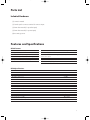
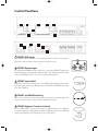
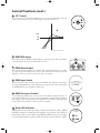
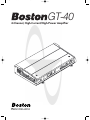
GT-40_manual
4/10/03
4:17 PM
Page 1
GT-40
4-Channel, High-Current/High-Power Amplifier
S ta
tus
On
Sa
fe
GT-40_manual
4/10/03
4:17 PM
Page 2
Table of Contents
Parts List
Features and Specifications
Control Functions
3
3
4
Control functions (cont.)
Control functions (cont.)
5
6
Mechanical Functions
6
Control cover removal & reinstallation
Multi-position mounting feet
Mechanical functions (cont.)
Amplifier linking
Wire connection
Fuses
General Installation Precautions
Before you install
Battery & charging system
Wire routing
Installation—Amplifier Mounting
Choose the mounting location
Installation—amplifier mounting (cont.)
Passenger & trunk compartment mounting
Installation—Fuses & Wiring
6
6
7
7
7
7
8
8
8
8
9
9
10
10
10
Amplifier fuses
Wire gauge
Installation—fuses & wiring (cont.)
Power/B+ & power/ground connection
Remote input connection
Speaker output connection
Installation—fuses & wiring (cont.)
Mono subwoofer operation
10
10
11
11
11
11
12
12
Setup Tuning—Full-range Speakers
12
Music
Front & rear sensitivity controls
Front & rear crossover controls
Setup tuning—full-range speakers (cont.)
Head unit
Volume
Front input sensitivity control
Front crossover controls
Setup tuning—full-range speakers (cont.)
Q-factor adjustments
Rear input sensitivity & crossover controls
12
12
12
13
13
13
13
13
14
14
14
Setup Tuning—Rear Fill Speakers & Subwoofers
Subwoofer level control
Rear input switch
Setup tuning—rear fill speakers & subwoofers (cont.)
Head unit
Volume
Rear input sensitivity control
Rear crossover control
Phase
System Examples
Amplifier Troubleshooting Guide
Contact and Warranty Information
2
14
14
14
14
15
15
15
15
15
16,17
18
19
GT-40_manual
4/10/03
4:17 PM
Page 3
Parts List
Included Hardware
(1) owner’s manual
(1) female quick-connect terminal for remote input
(1) 2mm hex wrench (for speaker input)
(1) 3mm hex wrench (for power input)
(4) mounting screws
Features and Specifications
GT-40 Features
4-Channel, High-Current Amplifier
2Ω Bridge Stable Operation
Power Increase with Input Voltage Rise
Advanced Cooling Allows Varied Mounting Positions
Adjustable Feet for Varied Mounting Surfaces
Security Cover Protects Control Settings
Continuously Variable Crossover and Q-factor Settings
Selectable Highpass Front Channels
Selectable Mono/Stereo Rear Highpass (Rear Fill) or
Subwoofer Lowpass
Selectable Rear Channel Signal Derived from Front Channel Input
Optional Remote Bass Control
Enhanced Switching Assignments
GT-40 Specifications
14.4VDC Power
@ 4 Ohms
@ 2 Ohms
@ 4 Ohms (dual-mono)
@ 2 Ohms (dual-mono)
4x55W
4x90W
2x190W
2x240W
12.6VDC Power
@ 4 Ohms
@ 2 Ohms
@ 4 Ohms (dual-mono)
@ 2 Ohms (dual-mono)
4x45W
4x70W
2x140W
2x190W
14.4VDC Multi-channel Power
12.6VDC Multi-channel Power
Frequency Response (-3dB)
Signal-to-Noise Ratio (A Weighted)
Dimensions
2x55W (4 ohm), 1x240W (2 ohm)
2x45W (4 ohm), 1x190W (2 ohm)
10Hz–95kHz
>100dB
21/4x141/8x8 7/8” (57 x 358 x 225mm)
3
GT-40_manual
4/10/03
4:17 PM
Page 4
Control Functions
3
5
9
12
10
6
4
4
11
1
2
7
8
12
1 FRONT RCA Inputs
RCA cables marked “FRONT” from head unit or from other line level device
should be connected here. Use both inputs (L & R) for stereo.
1
2
2 FRONT Remote Input
Use the supplied FEMALE quick connector to connect the REMOTE trigger lead
from the head unit to the amplifier. Amplifier turns “ON” when head unit is turned
“ON.” One FEMALE .210" connector is supplied with amplifier.
3 FRONT Input Switch
In the left position, the L & R inputs go to the FRONT L & R channels of the amplifier. In the right position, the L & R inputs go to the FRONT and REAR L & R channels of the amplifier.
4 FRONT and REAR Sensitivity
Turn control clockwise to increase the amplifier sensitivity to incoming signals. Turn
control counterclockwise to decrease the amplifier sensitivity.
5 FRONT Highpass Crossover Controls
To use 12dB/octave crossover, move switch to right-hand position. Highpass
crossover frequency is adjustable from 20Hz to 350Hz by rotary control. (Moving
switch to left-hand position will bypass crossover functions.)
4
GT-40_manual
4/10/03
4:17 PM
Page 5
Control Functions (cont.)
6 “Q” Control
“Q” Control is active when the highpass crossover is engaged and is centered
on the selected crossover point. The range of operation is 0.7–1.2.
dB
Q
+1.6dB
0dB
-3dB
.707 .95 1.2
t (tuned crossover frequency)
7 REAR RCA Inputs
RCA cables marked “REAR” from head unit or other line level device should be
connected here. Use both inputs (L & R) for stereo.
7
8
8 REAR Remote Input
This remote input is parallel to the FRONT remote input and does not need to
be connected for the amplifier to operate. Use either remote input to turn the
amplifier on. Do not connect 12V accessories to this input.
9 REAR Input Switch
In the left position, the L & R inputs go to the REAR L & R channels of the amplifier. In the right (MONO) position, the inputs are summed. Use this setting when
the REAR channels are used with a subwoofer.
10 REAR Crossover Controls
To use highpass 12dB/octave crossover, move left switch to upper position. To
use lowpass 12dB/octave crossover, move left switch to lower position. Highpass
and lowpass crossover frequencies are adjustable from 50Hz to 350Hz by rotary
control. Move filter switch to “ON” position to engage.
11 Status LED Indicators
GREEN indicates the normal operating condition; the amplifier is “ON.” GREEN
and RED together are normal when the amplifier is first turned “ON”; RED will
turn off after a few seconds. When both GREEN and RED remain on, the amplifier is in thermal shutdown condition. RED only indicates a fault condition, “SAFE.”
5
GT-40_manual
4/10/03
4:17 PM
Page 6
Control Functions (cont.)
12
Subwoofer Level Control Port
Switch should be set to “OFF” when control circuit is not installed,
(see optional “subwoofer level control” owner’s manual).
cover panel
Mechanical Functions
Recessed RCA Inputs
The input jacks are recessed into the body of the amplifier to provide clearance in tight mounting locations.
1 inch
1 inch
Control Cover Removal & Reinstallation
The cover panel is secured with two (2) captive coin-slotted screws. Coin-slotted
screws allow a coin edge to be used as a screwdriver to remove the panel.
Multi-position Mounting Feet
The mounting feet are designed to slide in both directions to clear installation
obstructions on the mounting surface.
WARNING! Before driving the mounting screws through any surface, be sure
of what is behind that surface. Check for the gas tank, brake lines, and any vehicle wiring harness.
Vents (Side & Rear)
The cooling vents must be kept clear of obstructions once the amplifier is installed. Failure to do this could
lead to premature thermal shutdown or amplifier failure.
upper side vent
6
lower side vent
GT-40_manual
4/10/03
4:17 PM
Page 7
Mechanical Functions (cont.)
Amplifier Linking
The design of the side panels enables multiple amplifiers to be used together without additional hardware.
Wire Connection
Amplifier accepts stripped wire directly into the terminal blocks. Speaker outputs accept 8-gauge, and the
DC power and ground accept 4-gauge. Tighten with supplied hex wrenches.
Fuses
Amplifier accepts standard AT-style automotive blade fuses.
7
GT-40_manual
4/10/03
4:17 PM
Page 8
General Installation Precautions
WARNING! Before driving the amplifier mounting screws through any surface, be sure of what is behind
that surface. Check for the gas tank, brake lines, and any vehicle wiring harness. Never run wires outside
or under the vehicle or where they could become broken or interfere with the safe operation of the
vehicle.
Before You Install
Before you install the unit, disconnect the negative (–) battery cable in the engine compartment of the vehicle. Doing so will prevent damage to both the electrical system of the vehicle and the amplifier during
installation.
Battery & Charging System
In order for the amplifier to function correctly, the electrical system of the vehicle should be professionally checked for overall electrical capacity. When used, the amplifier will increase the demand on the battery
and alternator. Therefore both should be thoroughly evaluated before installing the amplifier to ensure they
are in normal operating condition and able to handle the increased demand the amplifier will present to
the vehicle’s electrical system.
Wire Routing
Do not run the power wire near any low-level signals or audio cables such as the RCAs from the head
unit. (Noise can be introduced into the amplifier when this occurs.) It is helpful to diagram the wire layout
first before any installation is attempted.
8
GT-40_manual
4/10/03
4:17 PM
Page 9
Installation—Amplifier Mounting
Choose the Mounting Location
Plan your installation so that the amplifier is mounted where adequate ventilation is available.
Never mount an amplifier in the engine compartment of a vehicle!
WARNING! Before driving the mounting screws through any surface, be sure of what is behind that surface. Check for gas tank, brake lines, and any vehicle wiring harness.
13mm (1/2”)
225mm (87/8”)
57mm (21/2”)
358mm (141/8”)
9
GT-40_manual
4/10/03
4:17 PM
Page 10
Installation—Amplifier Mounting (cont.)
Passenger & Trunk Compartment Mounting
If the amplifier is mounted under a seat, be sure that the vents do not become
blocked. Do not allow seat padding or other obstructive material to press
down on the amplifier.
All Boston GT amplifiers have top panel controls. If the amplifier is mounted
under a seat, position the amplifier so the cover panel can be removed with
the seat forward or back to allow adjustment of the audio settings.
When mounting in a trunk, choose a location that will be protected from sliding cargo or other materials. Mount the amplifier to solid surfaces only. Do not
mount to plastic trim panels. Do not mount the amplifier with Velcro, doublestick tape, or by wedging into position. Amplifier should be mounted using
the movable mounting feet and the provided mounting screws.
Installation—Fuses & Wiring
Amplifier Fuses
Although the amplifier has internal fuses, additional fusing should be provided
at the battery on the positive (+) power wire going to the amplifier. An inline
fuse should be installed at no more than 18" (46cm) on the positive (+) power
wire. The rating of the inline fuse should equal the value of the internal fuses
of the amplifier if only the amplifier is connected to this wire. If other devices
are connected to this wire, the fuse value should be of sufficient capacity to
handle the demand.
Wire Gauge
The amplifier accepts up to 4-gauge stripped wire at the DC power and ground input terminals, and 4-gauge
is recommended. Wire runs should be kept to the minimum practical length.
10
GT-40_manual
4/10/03
4:17 PM
Page 11
Installation—Fuses & Wiring (cont.)
Power/B+ & Power/GND Connection
Strip approximately 5/8" (16mm) of insulation. The positive (+) power wire
is installed into the amplifier terminal marked “B+.” The negative (–) wire
is installed into the terminal marked “GND.” The ground wire should be
as short as possible and connected directly to the chassis of the vehicle.
Make sure that the chassis connection point is free of rust, grease, dirt,
paint, and other materials that may insulate the ground wire from making
proper connection. Tighten the B+ and GND terminals with the supplied
3mm hex wrench to secure the wire into the terminals. If the power wire
must be routed through a drilled or existing hole, use a nylon panel grommet to prevent fraying the wire insulation. Failure to do so could lead to
an electrical short if the wire insulation is worn through and the power wire
is shorted to ground.
1/ "
4
Strip 5/8" (16mm)
Remote Input Connection
Use the supplied FEMALE slide connector to connect the REMOTE trigger lead from the head unit to the amplifier. Crimp connector to wire from
head unit that controls remote turn-on (refer to head unit owner’s manual). Once the slide connector is crimped into place, carefully push connector
onto recessed male REMOTE terminal adjacent to the RCA Input pair. Only
one (1) remote turn-on terminal should be connected.
Speaker Output Connection
Prepare each wire by stripping approximately 5/8" (16mm) of insulation. The positive (+) speaker wire is
installed into the amplifier terminal marked “SPEAKER OUTPUT” / “+.” The negative (–) speaker wire is
installed into the amplifier terminal marked “SPEAKER OUTPUT” / “-.” Tighten the “Speaker Output”, “+”,
and “-” terminals with the supplied 2mm hex wrench to secure the wire into the terminals. If the speaker
wires must be routed through a drilled or existing hole, use a nylon panel grommet to prevent fraying the
wire insulation. Failure to do so could lead to an electrical short if the wire insulation is worn through and
the speaker wires are shorted to ground.
11
GT-40_manual
4/10/03
4:17 PM
Page 12
Installation—Fuses & Wiring (cont.)
Mono Subwoofer Operation
If the amplifier is to be bridged and used with a subwoofer connected to the REAR channels, use the
“SPEAKER OUTPUT” terminals marked for mono use.
WARNING! Subwoofer impedance must not fall below 2 ohms when in MONO mode.
2-ohm minimum
Setup Tuning—Full-range Speakers
1) Music
The material chosen for head unit/amplifier system setup must be both clear in recording quality and dynamic in amplitude. Many audiophile “test” discs have musical tracks with both of these characteristics and should
be used.
2) FRONT & REAR Sensitivity Controls
Turn controls all the way counterclockwise (minimum position). In this position,
the amplifier will be less sensitive to the input signal from the head unit.
3) FRONT & REAR Crossover Controls
Crossovers should be turned off during this phase of set-up. Move the HIGHPASS and FILTER switches to
the “OFF” position—with these settings, full-range signal is sent to the FRONT & REAR speaker outputs.
FRONT crossover control
12
REAR crossover control
GT-40_manual
4/10/03
4:17 PM
Page 13
Setup Tuning—Full-range Speakers (cont.)
4) Head Unit
The head unit should have all controls such as bass, treble, balance, and fader set to the flat or centered
position. The volume control should be at the minimum setting. If the head unit has any equalization or bass
management features such as boost, they should be defeated at this time. Turn head unit on, and verify
that the GREEN status LED is lit on the amplifier.
5) Volume
With the chosen musical track playing, turn the head unit volume control up until the maximum level of
undistorted signal is heard from the speakers. (For most head units, this will be near the end of the volume
control range.)
WARNING! A distorted signal from the head unit sent to the amplifier can cause loudspeaker failure at higher listening levels!
6) FRONT Input Sensitivity Control
Slowly rotate control clockwise until maximum undistorted playing level is heard
from the speakers. Listen closely for bottoming from the speakers. If detected, rotate FRONT Input Sensitivity counterclockwise until it is eliminated.
7) FRONT Crossover Controls
To achieve higher undistorted playing levels from the front speakers, the FRONT
crossover must be engaged. Rotate crossover control fully clockwise. The highpass crossover point is now set at 350Hz. Rotate FRONT “Q” Control fully counterclockwise. Move crossover switch to the right (ON) position.
Slowly rotate FRONT input sensitivity control clockwise until maximum undistorted playing level is heard from the speakers. Listen closely for bottoming from
the speakers. If detected, rotate FRONT input sensitivity control counterclockwise until it is eliminated. Slowly rotate FRONT highpass crossover control counterclockwise while listening for bottoming. You are lowering the
crossover point, which means that more bass signal is being sent to the speakers. If bottoming is detected, Rotate FRONT input sensitivity control counterclockwise until it is eliminated and/or rotate the FRONT
highpass crossover control clockwise to raise the crossover point.
13
GT-40_manual
4/10/03
4:17 PM
Page 14
Setup Tuning—Full-range Speakers (cont.)
8) FRONT “Q” Control
Once the FRONT highpass crossover point has been determined, use the
FRONT “Q” control to increase the bass information centered around the
crossover point.
Setting the front “Q” control is done in conjunction with setting the levels on
the input sensitivity and highpass crossover frequency controls. You may find
while setting the “Q” that bottoming may be detected in the front speakers;
lowering the “Q” input sensitivity or raising the highpass crossover point will
eliminate this. Minor adjustments to each setting are required to fine-tune the
system.
Setting the “Q” is a subtle process. It is recommended that the “Q” setting be left in the 0.7 position and
adjusted only after the input sensitivity and highpass crossover ranges are known. Small adjustments to the
“Q” setting are all that are required to fine-tune the system.
9) REAR Input Sensitivity & Crossover Controls
Setting levels for the rear channels proceeds the same as for the front except
for the elimination of the “Q” control settings. Crossover selector switch must
be set to “HP” and filter switch must be set to “ON.” If the loudspeaker being
used is capable of full-range operation, filter should be set to “OFF.”
Setup Tuning—Rear Fill Speakers
You may set the rear channels for summed mono operation from the L & R REAR RCA inputs by setting the
REAR INPUT switch to the right-hand MONO position and then connecting the L & R REAR loudspeakers
normally as you would for regular stereo operation. This configuration is beneficial for rear fill in some applications.
Setup Tuning—Subwoofers
1) SUBWOOFER LEVEL Control
Refer to subwoofer level control in owner’s manual. If the control is not used, SUBWOOFER LEVEL switch
must be set to “OFF.”
2) REAR Input Switch
Move switch to the right-hand (MONO) position, the inputs are summed to mono. Connect the subwoofer
to the REAR SPEAKER OUTPUT terminals marked for MONO operation. NOTE: Subwoofer impedance is
2 ohms minimum.
14
GT-40_manual
4/10/03
4:17 PM
Page 15
Setup Tuning—Subwoofers (cont.)
3) Head Unit
The head unit should have all controls such as bass, treble, balance, and fader
set to the flat or centered position. The volume control should be at the
minimum setting. If the head unit has any equalization or bass management
features such as boost, they should be deactivated at this time. Turn head unit
on, and verify that the GREEN status LED is lit on the amplifier.
4) Volume
With the chosen musical track playing, turn the head unit volume control up until the maximum level of
undistorted signal is heard from the speakers. For most head units, this will be at the end of the volume
control range.
WARNING! A distorted signal from the head unit sent to the amplifier can cause loudspeaker failure at
higher listening levels!
5) REAR Input Sensitivity Control
Turn controls all the way counterclockwise (minimum position). In this position, the amplifier will be less sensitive to the input signal from the head unit. Slowly rotate this control clockwise until maximum undistorted
playing level is heard from the subwoofers. Listen closely for faults such as bottoming from the subwoofer.
If fault is detected, rotate REAR input sensitivity control counterclockwise until fault is eliminated. At this
point, the maximum undistorted subwoofer playing level has been defined.
6) REAR Crossover Control
Move the selector switch to “LP” and the FILTER switch to “ON.” In this setting, lowpass signal is sent to
the REAR speaker outputs.
7) PHASE
Subwoofer phase is relative to the front loudspeakers. Correct electrical phase does not always mean
correct acoustic phase. Swap positive (+) and negative (-) connections at the speaker outputs where the
subwoofer is connected to the amplifier. It is beneficial to listen to the subwoofer connected in both phase
conditions. The subwoofer should be left in the condition in which the strongest bass response is noted.
15
GT-40_manual
4/10/03
4:17 PM
Page 16
System Examples
6.5LF
System A—Full-range Front with Full-range Rear
6.5LF
to ground
fuse
+ battery terminal
6.5LF
to
6.5LF
6.5LF
System B—Full-range Front with Rear Fill
6.5LF
to ground
fuse
+ battery terminal
6.5LF
to
6.5LF
16
GT-40_manual
4/10/03
4:17 PM
Page 17
System Examples (cont.)
6.5LF
System C—Main Speakers with Single Subwoofer (2Ω)
6.5LF
to ground
fuse
to
+ battery terminal
2Ω
10.5LF
6.5LF
System D —Main Speakers with Parallel 4Ω Subwoofers (2Ω load)
6.5LF
to ground
fuse
to
4Ω
10.5LF
+ battery terminal
4Ω
10.5LF
17
GT-40_manual
4/10/03
4:17 PM
Page 18
Amplifier Troubleshooting Guide
Status LEDs on Amplifier not Lit—Head Unit (Source) Turned “ON”
Verify
Remote turn-on wire from source to amplifier has proper voltage
Power (B+) connections at amplifier, terminal blocks, and battery are secure
Ground (GND) connections at amplifier and vehicle chassis are secure
Battery B+ fuse is OK
Amplifier fuse is OK
B+ at battery and B+ at amplifier have proper voltage
Status LEDs Lit, no Output from Speakers—Speakers in Normal Operating
Condition
Verify
High-level cables from speaker(s) to amplifier are securely connected
RCA cables from amplifier to source are securely connected
Sensitivity adjustment on amplifier is correctly adjusted
Engine Noise from Speaker(s)
Turn source “OFF”
Disconnect RCA cables at amplifier
If noise stops, check equipment & cables leading to amplifier
Verify
RCA cables are of good quality with no breakage to internal shields
RCA cables from source to amplifier are not run alongside power
Amplifier Output Distorted—Music not Recorded with Intentional Distortion
Verify
Source output to amplifier is not distorted
Amplifier input sensitivity is correctly adjusted
Amplifier Shuts Down, Red and Green LEDs are Lit—Amplifier is in Thermal
Protection Mode
Verify
Amplifier is mounted with adequate air circulation around vents
Amplifier does not have obstructions blocking back or side panel vents
Amplifier is not mounted under carpet
Speakers meet correct impedance for application (mono or stereo hookup)
Amplifier Does Not Turn “ON”, and Red LED is Lit—Amplifier not Connected to
a Shorted Speaker
Verify
Speaker crossover is not defective
High-level cables from speaker to amplifier are not shorted
Amplifier Does Not Turn “ON”, and Red LED Lit—Speakers, Crossovers, and
Cable are OK
Amplifier requires service
18
GT-40_manual
4/10/03
4:17 PM
Page 19
Contact and Warranty Information
Limited Warranty (US)
For one (1) year from the date of purchase, Boston Acoustics will repair for the original owner any defect in materials
or workmanship that occurs in normal use, without charge for parts and labor—when purchased from an authorized
Boston Acoustics retailer.
If an authorized Boston Acoustics retailer installs your amplifier, the warranty will be extended one (1) additional year.
Installation of the amplifier must be noted on the original purchase receipt. The receipt must be presented at the time
a warranty claim is made.
Your responsibilities are to use the system according to the instructions supplied, to provide safe and secure
transportation to an authorized Boston Acoustics service representative, and to present proof of purchase in the form
of your sales slip when requesting service.
Excluded from this warranty is damage that results from abuse, misuse, accidents, shipping, or repairs or modifications
by anyone other than an authorized Boston Acoustics service representative.
This warranty is void if the serial number has been removed or defaced.
This warranty gives you specific legal rights, and you may also have other rights that vary from state to state.
If Service Seems Necessary
First, contact the dealer from whom you purchased the amplifier. If that is not possible, write to:
Boston Acoustics, Inc. 300 Jubilee Drive Peabody, MA 01960 U.S.A., or your authorized Boston
Acoustics distributor
We will promptly advise you of what action to take. If it is necessary to return your unit to the factory, please ship it prepaid. After it has been repaired, we will return it freight prepaid in the U.S.A. and Canada.
Boston, Boston Acoustics, and the Boston logo are
registered trademarks of Boston Acoustics, Inc.
© 2003 Boston Acoustics, Inc. All rights reserved.
Specifications subject to change without notice.
www.bostonacoustics.com
300 Jubilee Drive
Peabody, MA 01960 U.S.A.
(978) 538-5000
P/N 042-001548-2
19