1
R4100A_Manual 2002-
25.02.2002
16:36 Uhr
Seite 1
INSTALLATION GUIDE
2-Channel Power Amplifier
2-Channel Power Amplifier
4-Channel Power Amplifier
R4100A_Manual 2002-
25.02.2002
16:36 Uhr
Seite 2
S2- AND 4-CHANNEL POWER AMPLIFIERS
2
R4100A_Manual 2002-
25.02.2002
16:36 Uhr
Seite 3
INHALTSVERZEICHNIS / CONTENTS
Seite
Seite
TECHNISCHE MERKMALE . . . . . . . . . . . . . . . . . . . . . . . . . . . . . 5
1. EINGÄNGE - AUSGÄNGE - BEDIENUNGSELEMENTE . 6-8
2. MONTAGE . . . . . . . . . . . . . . . . . . . . . . . . . . . . . . . . . . . . . . . . . . 9
2.1 WAHL DES EINBAUORTES . . . . . . . . . . . . . . . . . . . . . . . . . . 9
3. ELEKTRISCHER ANSCHLUSS. . . . . . . . . . . . . . . . . . . . . . . . 9
3.1 VERLEGEN VON CINCHKABEL / REMOTE-KABEL . . . 10
3.2 ANSCHLUSS DER LAUTSPRECHER-KABEL . . . . . . . . 10
3.3 ANSCHLUSS DER POWER-KABEL . . . . . . . . . . . . . . . . . 10
3.4 ERSTE FUNKTIONSPRÜFUNG . . . . . . . . . . . . . . . . . . . . . 10
SYSTEMKONFIGURATIONEN . . . . . . . . . . . . . . . . . . . . . . 11-15
4. EINSTELLUNG DER INTEGRIERTEN
FREQUENZWEICHEN . . . . . . . . . . . . . . . . . . . . . . . . . . . . . . . . . 16
4.1 MINIMALE LASTIMPEDANZ . . . . . . . . . . . . . . . . . . . . . . . . 16
4.2 WÄHLEN DES BETRIEBSMODUS . . . . . . . . . . . . . . . . . . 16
4.3 TRENNFREQUENZ EINSTELLUNGEN . . . . . . . . . . . . . . . 16
4.3.1 HIGHPASS FÜR KOMPONENTEN
UND KOAXIAL SYSTEME . . . . . . . . . . . . . . . . . . . . . . . . . . . . . 16
4.3.2 BANDPASS FÜR KICKBASS SYSTEME. . . . . . . . . . . . 17
4.3.3 BANDPASS FÜR SUBWOOFER SYSTEME . . . . . . . . . 17
4.4 ANPASSUNG DER EINGANGSEMPFINDLICHKEIT . . . 18
4.5 PHASE-SHIFT EINSTELLUNG . . . . . . . . . . . . . . . . . . . . . . 18
TECHNICAL FEATURES . . . . . . . . . . . . . . . . . . . . . . . . . . . . . . 20
1. INPUTS - OUTPUTS - CONTROLS . . . . . . . . . . . . . . . . 21-23
2. MOUNTING OF THE AMPLIFIER . . . . . . . . . . . . . . . . . . . . . 24
2.1 MOUNTING LOCATION . . . . . . . . . . . . . . . . . . . . . . . . . . . . 24
3. ELECTRICAL WIRING . . . . . . . . . . . . . . . . . . . . . . . . . . . . . . . 24
3.1 RCA INTERCONNECTS / REMOTE LEAD. . . . . . . . . . . . 25
3.2 LOUDSPEAKER CABLES . . . . . . . . . . . . . . . . . . . . . . . . . . 25
3.3 CONNECTION OF POWER CABLES . . . . . . . . . . . . . . . . . 25
4. CROSSOVER SETTINGS . . . . . . . . . . . . . . . . . . . . . . . . . . . . 26
4.1 MINIMUM IMPEDANCE LOAD . . . . . . . . . . . . . . . . . . . . . . 26
4.2 SELECTING THE OPERATION MODE. . . . . . . . . . . . . . . . 26
4.2.1 HIGHPASS FOR COMPONENT
AND COAXIAL SPEAKERS . . . . . . . . . . . . . . . . . . . . . . . . . . . . 26
4.2.2 BANDPASS FOR KICKBASS SYSTEMS . . . . . . . . . . . 27
4.2.3 BANDPASS FOR SUBWOOFER SYSTEMS . . . . . . . . . 27
4.2.4 ADJUSTING INPUT SENSITIVITY . . . . . . . . . . . . . . . . . 27
4.3 ADJUSTMENT OF PHASE SHIFT CONTROL. . . . . . . . . 28
5. TECHNICAL SPECIFICATIONS. . . . . . . . . . . . . . . . . . . . . . . 29
6. WARRANTY. . . . . . . . . . . . . . . . . . . . . . . . . . . . . . . . . . . . . . . . 31
6. GARANTIEBESTIMMUNGEN . . . . . . . . . . . . . . . . . . . . . . . . 31
GARANTIE-KARTE / WARRANTY-CARD
3
R4100A_Manual 2002-
25.02.2002
16:36 Uhr
Seite 4
2- AND 4-CHANNEL POWER AMPLIFIER
Herzlichen Glückwunsch!
Wir gratulieren Ihnen zum Kauf dieser RODEK Car-Hifi
Endstufe.
Damit Sie die Wiedergabequalität und die Leistungsfähigkeit dieses Verstärkers voll ausschöpfen können, bitten wir
Sie, sich eingehend mit den Möglichkeiten und technischen
Features dieses Car-Amps vertraut zu machen. Lesen Sie
deshalb die nachfolgenden Abschnitte sorgfältig durch und
bewahren Sie diese Bedienungsanleitung für eventuell später auftauchende Fragen auf.
Falls Sie weitere Fragen bezüglich der Anschluss- oder Einstellmöglichkeiten dieses Gerätes, oder dessen Installation
haben, lassen Sie sich von Ihrem autorisierten RODEK
Fachhändler beraten.
4
R4100A_Manual 2002-
25.02.2002
16:36 Uhr
Seite 5
TECHNISCHE MERKMALE
■ Car-Hifi Verstärker zur Realisierung eines einbaufreundlichen, leistungs- und klangstarken System Konzeptes
■ Phase Shift Control, variabel zwischen 0-180°
■ Zwei MOSFET Netzteile (R4100A / R2180A) sorgen für
kräftige Ausgangsleistung und hohe Stabilität
■ Innovatives Gehäusedesign mit Clam-Shell Aluprofil
Kühlkörper und innenliegendem, temperaturgesteuertem Lüfter
■ 2 Ohm Last-Stabilität aller Kanäle, jedes Kanalpaar lässt
sich im Brückenmodus betreiben
■ Massive gekapselte Anschlussblöcke für Power-Eingänge und Lautsprecher Ausgänge
■ Integrierte elektronische Frequenzweichen mit Flankensteilheiten von 12 dB/Okt. Pro Kanalpaar wahlweise
Hochpass (Subsonic), Bandpass oder Fullrange
Operation möglich. Einstellbereich der Trennfrequenz
stufenlos regelbar zwischen 10Hz - 400Hz im Hochpass
Betrieb und 30Hz bis 400Hz bei Tiefpass Betrieb, respektive beide kombiniert als Bandpass
■ Regelbare Eingangsempfindlichkeit mit einem großem
Einstellbereich von 0.2V bis 9V
■ Intelligente Schutzschaltung, welche Kurzschlüsse an
den Lautsprecherausgängen, Gleichspannung im Ausgangssignal und überhöhte Betriebstemperatur erkennt.
5
R4100A_Manual 2002-
25.02.2002
16:36 Uhr
Seite 6
1. EINGÄNGE - AUSGÄNGE - BEDIENUNGSELEMENTE
1. Cinch Eingangsbuchsen (CH1/CH2, CH3/CH4; jeweils
immer linker und rechter Kanal). NF-Signal Eingang für den
Anschluss der Cinch-Ausgänge des Steuergerätes
9. Regler zum Einstellen der Tiefpass-Trennfrequenz der
Kanäle CH3/4 (LOWPASS) an der integrierten elektronischen Frequenzweiche
2. Eingangsempfindlichkeitsregler - LEVEL - des
Kanalpaares CH1/2 für die Anpassung an die Ausgangsspannung des Steuergerätes
10. Schiebeschalter - PHASE - zum aktivieren/deaktivieren des stufenlosen Phase-Shifts
11. Regler zum Einstellen der Phase
3. Schiebeschalter zum Wählen des Betriebsmodus FULL, HIGHPASS oder BANDPASS - der Aktivweiche für
die Kanäle CH1/2
12. LED Statusanzeige, leuchtet grün wenn die Endstufe
eingeschaltet und betriebsbereit ist
4. Regler zum Einstellen der Hochpass/Subsonic-Trennfrequenz der Kanäle CH1/2 (HIGHPASS) an der integrierten
elektronischen Frequenzweiche
13. LED Statusanzeige, leuchtet rot bei Defekt, Kurzschluss am Eingang und bei Überhitzung der Endstufe
14. Anschlussklemmen für die Lautsprecher
5. Regler zum Einstellen der Tiefpass-Trennfrequenz der
Kanäle CH1/2 (LOWPASS) an der integrierten elektronischen Frequenzweiche
15. Sicherungen
6. Eingangsempfindlichkeitsregler - LEVEL - des
Kanalpaares CH3/4 für die Anpassung an die Ausgangsspannung des Steuergerätes
17. "GND" für den Anschluss an die Chassis-Masse des
Kfz
7. Schiebeschalter zum Wählen des Betriebsmodus FULL, BANDPASS oder HIGHPASS - der Aktivweiche für
die Kanäle CH3/4
18. "REM" (Remote) Anschluss für die Ein- bzw. automatische Abschaltung des Verstärkers über den Amp- oder Antenna-Remote Anschluss des Steuergerätes
8. Regler zum Einstellen der Hochpass/Subsonic-Trennfrequenz der Kanäle CH3/4 (HIGHPASS) an der integrierten
elektronischen Frequenzweiche
6
16. "+ 12 V" für den Anschluss an den Pluspol der Autobatterie über eine Haupt-Sicherung
R4100A_Manual 2002-
25.02.2002
16:36 Uhr
Seite 7
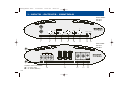
1. EINGÄNGE - AUSGÄNGE - BEDIENUNGSELEMENTE
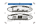
FRONT PANEL
R2100A
R2180A
CH 1
90°
FULL
9V
CH 2
0.2V
LEVEL
PHASE
HP
BP
10Hz
400Hz 30Hz
400Hz
HIGH PASS
LOW PASS
4
5
ON
OFF
0
POWER
180°
PROTECT
PHASE
CH 1/2
1
2
3
10
11
12
13
REAR PANEL
R2100A
R2180A
A
FUSE
FUSE
FUSE
BRIDGED
CH2
CH2
CH1
CH1
+12V
GND
REM
B
Amplifier internal ventilation
A = air inlets (top)
B = air outlets (bottom)
14
15
16
17
18
7
R4100A_Manual 2002-
25.02.2002
16:36 Uhr
Seite 8
1. EINGÄNGE - AUSGÄNGE - BEDIENUNGSELEMENTE
1
1
6
CH 1
CH 3
7
FULL
9V
0.2V
LEVEL
9V
CH 4
BP
1
0.2V
1
11
FRONT PANEL
R4100A
400Hz 30Hz
HIGH PASS
400Hz
LOW PASS
0
PHASE
180°
PHASE
HP
BP
CH 1/2
2
10
ON OFF
10Hz
CH 3 /4
LEVEL
9
HP
FULL
CH 2
8
3
10Hz
400Hz 30Hz
400Hz
HIGH PASS
LOW PASS
4
5
POWER
12
PROTECT
13
REAR PANEL
R4100A
A
FUSE
BRIDGED
CH4
CH4
CH3
FUSE
FUSE
BRIDGED
CH3
CH2
CH2
CH1
CH1
+12V
GND
REM
B
Amplifier internal ventilation
A = air inlets (top)
B = air outlets (bottom)
8
14
15
16
17
18
R4100A_Manual 2002-
25.02.2002
16:36 Uhr
Seite 9
2. MONTAGE
Bevor Sie mit der Montage beginnen, erstellen Sie am besten eine kurze Anschluss- und Installationsskizze. Beachten Sie bitte, dass die Kabelführung und der gewählte Massepunkt einen entscheidenden Einfluss auf das störungsfreie Funktionieren Ihrer Anlage hat.
Besondere Aufmerksamkeit verdient auch die korrekte Platzierung des Verstärkers (ausreichende Luftzufuhr!), sowie
die Qualität des verwendeten Zubehörs zur fachgerechten
Installation (Stromkabel, Cinchkabel, Sicherungshalter, Verteilerblöcke, etc).
2.1 WAHL DES EINBAUORTES
Der Montageort des Verstärker muss im Sinne einer guten
Wärmeabführung als auch für die weiteren Einstellarbeiten
an der Aktivweiche des Verstärkers entsprechend platziert
werden.
Als Montageort eignet sich z.B. ein Platz im Kofferraum, an
der Rücksitzbank oder an einem Seitenteil, bzw. jeder andere Ort der eine saubere Installation ermöglicht.
Die Endstufe wird im Betrieb heiß, es sollte also einen Abstand von mindestens 5 cm oberhalb und auf den Seiten des
Alu-Kühlkörpers geachtet werden. Der Luftein- und Auslass (innenliegender Lüfter!) befindet sich in den Seitenabdeckungen. Dort sollte genügend Luft zirkulieren können!
Vermeiden Sie Montageorte mit "unbekanntem Hintergrund". Es könnten sich der Benzintank, hydraulische
Bremsleitungen, Kabel etc. dahinter verbergen! Achten Sie
auch auf einen trocken, gegen mechanische Einwirkungen
geschützten Installationsort, der auch nach der Endmontage noch für die Bedienung und Einstellung (Trennfrequenzund Eingangsempfindlichkeits- Regelung) des Verstärkers
gut zugänglich ist. Die Endstufe darf nicht mit der KfzChassismasse in Berührung kommen, sie muss also in jedem Fall isoliert montiert werden.
3. ELEKTRISCHER ANSCHLUSS
ACHTUNG! Entfernen Sie vor Beginn der Arbeiten
immer das Pluskabel vom Pluspol der Batterie !!
Bei allen nachfolgend beschriebenen Installationsschritten muss der Stromkreis des Kraftfahrzeugs
unterbrochen sein! Erst nach Abschluss aller Installationsarbeiten wird über das Pluskabel der Stromkreis wieder geschlossen.
Der Stromkabelquerschnitt der Plus- und Minusleitung (bei
einer Kabellänge von ca. 5m) sollte mindestens 20mm2, besser jedoch 35mm2 betragen. Bedenken Sie, dass z.B. beim
Einsatz einer weiteren (zweiten) Endstufe der Strombedarf
nochmals entsprechend ansteigt. In diesem Falle (bei zwei
Endstufen) sind 35mm2 Power Kabel Querschnitt das Minimum!
Zu gering gewählte Batteriekabelquerschnitte führen zu einer übermäßigen Erhitzung der Endstufe(n), dies lässt die
Thermosicherung ansprechen und schaltet die Endstufe(n)
aus!
Verwenden Sie beim Einziehen der Stromkabel Kabeltüllen
aus Gummi, um ein Durchscheuern an Blechkanten, respektive den dadurch resultierenden Kurzschluss auf Chassismasse zu vermeiden!
9
R4100A_Manual 2002-
25.02.2002
16:36 Uhr
Seite 10
3. ELEKTRISCHER ANSCHLUSS
Speziell die musiksignalführenden (Cinch-) Kabel müssen
soweit wie möglich von allen potentiellen "elektrischen
Störsendern" wie Bordcomputer, Benzinpumpe, Kabelbäumen, Stromversorgungskabel für die Beleuchtung, etc. verlegt werden!
3.1 VERLEGEN VON CINCHKABEL /
REMOTE-KABEL
Verlegen Sie nun das (oder die) Cinchkabel und das Remote-Kabel vom Steuergerät zur Endstufe. Diese Kabel sollten
unbedingt räumlich getrennt von der Stromzuführung des
Verstärkers eingezogen werden. Verwenden Sie mindestens
doppelt oder besser dreifach geschirmte Cinch-Kabel!
Schließen Sie das Remote-Kabel an die mit "REM" bezeichnete Klemme an der Endstufe und an das mit "AntennaRem." oder "Amplifier-Rem." bezeichnete Kabel Ihres Steuergerätes an. Das Remote-Kabel führt eine 12 V Schaltspannung die den Verstärker einschaltet, wenn Sie das
Steuergerät aktivieren. Anschließend stecken Sie die Cinchkabel in die Cincheingangsbuchsen des Verstärker ein.
3.2 ANSCHLUSS DER
LAUTSPRECHER-KABEL
Verwenden Sie Lautsprecherkabel mit 2,5 mm2 Querschnitt.
Für den Anschluss am Verstärker benötigen Sie InbusSchlüssel der geeigneten Größe, sowie ein Messer oder
eine Abisolier-Zange. Entfernen Sie ca. 6-8 mm der Isolierung des LS-Kabels und beachten Sie beim Anschluss der
Kabel am Verstärker unbedingt die richtige Polung der Lautsprecherkabel (Plus auf Plus, Minus auf Minus) Ziehen Sie
die LS-Schraublemmen satt an.
10
3.3 ANSCHLUSS DER POWER-KABEL
Verlegen Sie nun das Pluskabel direkt von der Batterie zum
Verstärker. Innerhalb der ersten 30 cm nach dem Pluspolklemmenabgriff muss eine Hauptsicherung angebracht
werden. Diese sollte auf den Kabelquerschnitt und die maximale Stromaufnahme des Verstärkers abgeglichen werden.
Minimum 80A sind angebracht! Die Hauptsicherung dient
zur Absicherung des Pluskabels gegen Kurzschluss auf
Fahrzeug-Masse und den dadurch resultierendem Kabelbrand (Vorschrift der Kfz-Versicherungen!!)
Nun schließen Sie das Minuskabel am Verstärker und am
Fahrzeug an. Versuchen Sie dieses Kabel so kurz wie möglich zu halten. Es sollte denselben Querschnitt wie das Pluskabel besitzen. Verwenden Sie für den Massepunktanschluss einen vergoldeten Ringkabelschuh oder noch besser eine solide Massenklemme. Achten Sie auf eine perfekt
gesäuberte blanke Metalloberfläche am Fahrzeug (schlechte Massepunkte sind für über 90 % aller Fälle der auftretenden Störungen verantwortlich).
3.4 ERSTE FUNKTIONSPRÜFUNG
Drehen Sie den oder die LEVEL Regler am Verstärker im Gegenuhrzeigersinn auf Linksanschlag. Schließen Sie nun den
Stromkreis zum Verstärker durch das Einsetzen der Hauptsicherung. Ihr RODEK Verstärker sollte nun beim Einschalten des Steuergerätes durch aufleuchten der grünen PowerLED die Betriebsbereitschaft anzeigen. Leuchtet die rote
PROTECT-LED auf, ist Ihre Installation fehlerhaft. Schalten
Sie sofort wieder aus und gehen Sie die oben aufgeführten
Installationsanweisungen nochmals genau durch.
R4100A_Manual 2002-
25.02.2002
16:36 Uhr
Seite 11
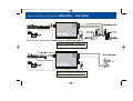
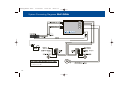
System Connecting Diagrams R2100A / R2180A
CH 1
CH1
CH 2
CH2
OPERATION MODE SELECTOR
CH1/2 set to HP
CH1
CH2
OPERATION MODE SELECTOR
CH1/2 set to BP
11
R4100A_Manual 2002-
25.02.2002
16:36 Uhr
Seite 12
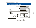
System Connecting Diagrams R2100A / R2180A / R4100A
CH1
CH2
OPERATION MODE SELECTOR
CH1/2 set to BP
CH1
CH2
CH3
CH4
OPERATION MODE SELECTOR
CH1/2 set to HP
CH3/4 set to BP
12
R4100A_Manual 2002-
25.02.2002
16:36 Uhr
Seite 13
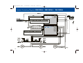
System Connecting Diagrams R4100A
CH1
CH2
CH3
CH4
MID/
WOOFER
MID/
WOOFER
MID/
WOOFER
MID/
WOOFER
OPERATION MODE SELECTOR
CH1/2 set to HP
CH3/4 set to HP
13
R4100A_Manual 2002-
25.02.2002
16:36 Uhr
Seite 14
System Connecting Diagrams R4100A
CH1
CH2
CH3
CH4
OPERATION MODE SELECTOR
CH1/2 set to HP
CH3/4 set to BP
14
R4100A_Manual 2002-
25.02.2002
16:36 Uhr
Seite 15
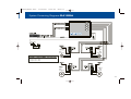
System Connecting Diagrams R4100A
CH1
CH2
CH3
CH4
OPERATION MODE SELECTOR
CH1/2 set to HP
CH3/4 set to BP
16CM
KICKBASS SYSTEM
16CM
KICKBASS SYSTEM
15
R4100A_Manual 2002-
25.02.2002
16:36 Uhr
Seite 16
4. EINSTELLUNG DER INTEGRIERTEN FREQUENZWEICHEN
4.1 MINIMALE LASTIMPEDANZ
Die RODEK Verstärker sind von der Auslegung der Endtransistoren-Sektion auf eine sehr hohe Ausgangsleistung im 4
und 2 Ohm stereo Betrieb ausgelegt, sie bieten hier eine gemessen am Preis überdurchschnittliche Performance. Die
RODEK Verstärker können auf eine 4 Ohm Last gebrückt
werden. Im Stereobetrieb darf die minimale Abschlussimpedanz von 2 Ohm pro Kanal auf keinen Fall unterschritten
werden. Dasselbe gilt auch für den Brückenmodus, wo 4
Ohm die minimal zulässige Lastimpedanz darstellen!
4.2 WÄHLEN DES BETRIEBSMODUS
Je nach Verwendung dieses Verstärkers müssen Sie nun
den oder die Schiebeschalter für die jeweiligen Betriebsmodi der Kanäle in die benötigte Stellung bringen. Hiermit
wird der Arbeitsbereich des angeschlossenen Lautsprecherpaars definiert. Also z.B. HIGHPASS wenn am betreffenden Kanalpaar ein Kompo- oder Koaxsystem angeschlossen ist, BANDPASS im Falle eines Kickbass-Systemes oder eines Subwoofers, respektive FULL, wenn die entsprechenden Filter schon über eine DSP Funktion im HeadUnit vorgewählt werden können.
4.3 TRENNFREQUENZ EINSTELLUNGEN
Die Hochpass-, Tiefpass- und Bandpassfunktion der integrierten Frequenzweichen Ihres Verstärkers teilt den eingesetzten Lautsprechersystemen wie Subwoofer, Koax- oder
Komponentensystemen nur den Frequenzbereich zu, für
welchen die Lautsprecher geeignet sind. Bevor abschließend die Eingangsempfindlichkeitsanpassung jedes
16
Kanalpaares in Angriff genommen werden kann, gilt es
zunächst die groben Trennfrequenzen für die angeschlossenen Lautsprecher vorzuwählen.
4.3.1 HIGHPASS FÜR KOMPONENTEN
UND KOAXIAL SYSTEME
Zuallererst müssen am Steuergerät alle Klangregler (Bass,
Treble), Fader als auch die Loudnessfunktion in die Mittel- oder
Neutral- Position gebracht werden.
Die Einstellung der Trennfrequenzen der Weichenzweige sollte gemäss den ungefähren nachfolgend gemachten Vorgaben
erfolgen. Die HochpassTrennfrequenz stellt immer einen Kompromiss zwischen der möglichen Pegelfestigkeit und der Midbass-Wiedergabe dar. Versuchen Sie eine Einstellung zu finden, die Ihrem Hörgeschmack als auch der Pegelfestigkeit der
angeschlossenen Kompo-/Koax Lautsprechern Rechnung
trägt.
Satelliten-System in den Vordertüren, empfohlene Trennfrequenz Highpass
10 cm Koax- oder Komponentensysteme 90 - 120 Hz
13 cm Koax- oder Komponentensysteme 80 - 100 Hz
16 cm Koax- oder Komponentensysteme 60 - 90 Hz
Satelliten-System in den Hintertüren oder der Heckablage,
empfohlene Trennfrequenz Highpass
10 cm Koax- oder Komponentensysteme 100 - 150 Hz
13 cm Koax- oder Komponentensysteme 120 - 150 Hz
16 cm Koax- oder Komponentensysteme 130 - 150 Hz
R4100A_Manual 2002-
25.02.2002
16:36 Uhr
Seite 17
4. EINSTELLUNG DER INTEGRIERTEN FREQUENZWEICHEN
4.3.2 BANDPASS FÜR KICKBASS
SYSTEME
Für den Betrieb von Kickbässen kommen zwei Filter, die
nacheinander geschaltet sind, zum Einsatz. Der Weichenzweig läuft also im Bandpass Modus, entsprechend einem
Hochpass (10-400Hz) mit nachgeschaltetem Tiefpass (30400 Hz). Das Hochpassfilter wird in der Regel um mindestens Faktor zwei kleiner eingestellt, wie die nachfolgende
Tiefpass-Trennfrequenz. Das Tiefpassfilter selbst sollte
meist leicht niedriger gewählt werden, wie die HochpassTrennfrequenz der beiden Kanäle, welche die Kompo/Koax
Lautsprecher treiben.
Kickbass-System in den Vordertüren, empfohlene Trennfrequenz Bandpass
16 cm Kickbassysteme
80 - 110 Hz Hochpass
200 - 250 Hz Tiefpass
4.3.3 BANDPASS FÜR SUBWOOFER
SYSTEME
Die aktive Frequenzweiche für den oder die angeschlossenen Subwoofer läuft auch im Bandpass Modus. Hierzu wird
zuerst der Highpass Regler des betreffenden Kanalpaares
im Gegenuhrzeigersinn auf 10Hz gestellt. Er wird nach der
Einstellung der Subwoofer (Lowpass) Trennfrequenz später
noch ermöglichen, das Subwoofer System etwas pegelfester zu machen.
Nun wird zuerst die Tiefpass (Lowpass) Frequenz am betreffenden Regler eingestellt. Sinnvollerweise sollte diese im
Bereich zwischen 50 bis 90 Hz liegen. Justieren Sie den
Regler nach Gehör, dass der Klang im Bassbereich satt und
trocken mit genügend Tiefbassanteil wiedergegeben wird.
Dazu müssen Sie das Head Unit einschalten und den Level
Regler des Kanalpaares welches den Subwoofer treibt auf
ca. auf 12 Uhr aufdrehen, damit der Subwoofer gut hörbar
wird. Eine zu tiefe Trennfrequenz lässt den Bassbereich tiefbassbetont, kraftlos und unkonturiert wirken. Eine zu hohe
Trennfrequenz bewirkt ein Dröhnen des Bassbereichs. Ist
diese Einstellung gefunden, sollte der Highpass Regler, der
hier als Subsonicfilter verwendet wird, eingestellt werden.
Er schneidet extrem tiefe Frequenzen, welche der angeschlossene Subwoofer nicht mehr wiedergeben kann ab.
Drehen Sie also den Highpass Regler des Subwoofer Kanalpaares (meist CH3/4) soweit im Uhrzeigersinn auf, bis Sie
gerade hören, dass die Basswiedergabe "dünner" wird.
Abschließend - nach der gleich folgenden Einstellung der
Eingangsempfindlichkeit - sollte noch eine Feineinstellung
der oben grob gesetzten Bandpass Trennfrequenz(en) erfolgen. Diese Feineinstellung muss gehörmässig erfolgen und
orientiert sich am akustisch harmonischen Zusammenspiel
der diversen installierten Lautsprechersysteme.
17
R4100A_Manual 2002-
25.02.2002
16:36 Uhr
Seite 18
4. EINSTELLUNG DER INTEGRIERTEN FREQUENZWEICHEN
4.4 ANPASSUNG DER EINGANGSEMPFINDLICHKEIT
Die korrekte Eingangsempfindlichkeitseinstellung ist wichtig für die Ausnutzung des optimalen Dynamikspielraumes
Ihrer Steuergerät / Verstärker / Lautsprecherkombination.
Diese Empfindlichkeitseinstellung beeinflusst das Grundrauschen ebenso wie die verzerrungsfrei erzielbare Maximallautstärke.
Schalten Sie das Steuergerät ein. Stellen Sie nun den
Lautstärkeregler Ihres Steuergerätes auf ca. 3/4 der Maximallautstärke und verwenden Sie für die nun kommende
Einstellung ein gut aufgenommenes, dynamikreiches Musikstück.
Erhöhen Sie nun den Level vom Kanalpaar, welches den
oder die Subwoofer antreibt. Drehen Sie gerade soweit auf,
bis Sie deutliche Verzerrungen im Bassbereich hören. Reduzieren Sie die Lautstärke am Head-Unit auf ein mittleres
Maß und drehen Sie nun den LEVEL Regler des Kompo/Koax oder Kickbass Kanalpaares am Verstärker langsam
auf, bis sich ein gut ausbalanciertes Klangbild mit leichter
Bass (oder Kickbass)betonung einstellt. Nun können Sie falls noch weitere Lautsprechersysteme und/oder Verstärkerkanäle vorhanden sind - mit den jeweiligen Level Reglern
einpegeln.
Eine leichte Bassbetonung ist übrigens vorzuziehen, weil
sie später von den auftretenden Fahrgeräuschen wieder
überdeckt wird.
18
4.5 PHASE SHIFT EINSTELLUNG
Der Phase-Shift Regler ermöglicht die Beeinflussung der
Phasenlage des angeschlossenen Subwoofer Systems. Mit
diesem Regler - und gegebenenfalls durch zusätzliches
Umpolen des Subwoofers, ist es möglich eine perfekte akustische Phaselage zwischen dem Subwoofer und dem
Frontsystem (oder auch den Kickbässen, wenn vorhanden)
zu erzielen. Wenn die Einstellung "passt", ist der Subwoofer
nicht mehr im Kofferraum des Fahrzeuges ortbar, und die
subjektive Sauberkeit der Wiedergabe des oberen Bassbereiches nimmt zu. Die Anpassung der Phasenlage des Subwoofers lässt sich nur mit der Hilfe einer zweiten Person
bewerkstelligen. Der hörbare Effekt, wenn der Phase-Shift
Regler verstellt wird, muss auf dem Fahrersitz beurteilt werden. Wenn Ihnen diese Einstellung zu tricky ist, kann auch
nur mittels umpolen des Subwoofers die generell richtigere
Anschlussvariante ausgetestet werden, hier wird dann der
Phase-Shift mittels Schiebeschalter auf OFF abgeschaltet.
R4100A_Manual 2002-
25.02.2002
16:36 Uhr
Seite 19
Congratulations!
and thank you for choosing this RODEK Car Audio Power
Amplifier!
To maximize the performance of your complete car audio
system, it is recommended that you acquaint yourself
thoroughly with the capabilities and features of this amplifier. Therefore read this manual carefully, before attempting the installation of this multichannel amplifier
and retain the manual and your purchasing/installation
receipts for future reference.
19
R4100A_Manual 2002-
25.02.2002
16:36 Uhr
Seite 20
TECHNICAL FEATURES
■ Car audio amplifier for a compact and user friendly
realization of a powerful car audio system.
■ Two independent MOSFET power supplies (R4100A /
R2180A) for high power output and best stability into
low impedance loads
■ Versatile integrated electronic crossovers with filter
slopes of 12/dB/octave. Independently selectable
operation modes: Highpass, bandpass and
fullrange. Fully variable crossover frequency ranges
in between 10Hz - 400Hz for highpass, and 30Hz 400Hz for lowpass, or both cascaded for bandpass
operation.
■ Phase shift control, fully variable in between 0-180°
20
■ Uncompromising heatsink design, introducing a new
clamshell structure with temperature controlled
internal fan
■ CNC machined power input and speaker output
blocks
■ Adjustable input sensitivity, fully variable from 0.2V
to 9V
■ Advanced protection circuitry, sensing overload,
short-circuits at the speaker outputs, DC voltage at
the outputs and overheating of power electronics
R4100A_Manual 2002-
25.02.2002
16:36 Uhr
Seite 21
1. INPUTS - OUTPUTS - CONTROLS
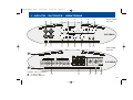
1. RCA inputs (CH1/2, CH3/4, left and right channels).
Line inputs for connection with RCA line-out’s of the
head-unit
2. Input gain control LEVEL adjustment for channels
CH1/2. Used to match the RCA line output voltage of the
head-unit to the amplifier input section.
3. Operation mode selector, slide switch to select Highpass, Bandpass or Fullrange operation of the active
crossover for channels CH1/2
4. Highpass crossover frequency control, to adjust
the cut-in frequency of the channels CH1/2
5. Lowpass crossover frequency control, to adjust
the cut-off frequency of the channels CH1/2
9. Lowpass crossover frequency control, to adjust
the cut-off frequency of the channels CH3/4
10. Slide switch to activate/deactivate the phaseshift control
11. Phase-shift control, to alter the acoustical phase
of the output signal
12. Operation LED, is lit green when power is on
13. Protection LED, is lit red when the amplifier is shut
down because of malfunction, overheating or short-cut
on speaker cable leads
14. Terminal block for the speaker wire connection
15. Fuses
6. Input gain control LEVEL adjustment for channels
CH3/4. Used to match the RCA line output voltage of the
head-unit to the amplifier input section.
7. Operation mode selector, slide switch to select Highpass, Bandpass or Fullrange operation of the active
crossover for channels CH3/4
8. Highpass crossover frequency control, to adjust
the cut-in frequency of the channels CH3/4
16. "+12V" for connection to the positive terminal of car
battery
17. "GND" for connection to chassis ground or negative
terminal of car battery
18. "REM" for the automatic (remote) turn-on / turn-off
of the power amplifier from the head-unit's remote or antenna control lead
21
R4100A_Manual 2002-
25.02.2002
16:36 Uhr
Seite 22
1. INPUTS - OUTPUTS - CONTROLS
FRONT PANEL
R2100A
R2180A
CH 1
90°
FULL
9V
CH 2
0.2V
LEVEL
PHASE
HP
BP
10Hz
400Hz 30Hz
400Hz
HIGH PASS
LOW PASS
4
5
ON
OFF
0
POWER
180°
PROTECT
PHASE
CH 1/2
1
2
3
10
11
12
13
REAR PANEL
R2100A
R2180A
A
FUSE
FUSE
FUSE
BRIDGED
CH2
CH2
CH1
CH1
+12V
GND
REM
B
Amplifier internal ventilation
A = air inlets (top)
B = air outlets (bottom)
22
14
15
16
17
18
R4100A_Manual 2002-
25.02.2002
16:36 Uhr
Seite 23
1. INPUTS - OUTPUTS - CONTROLS
1
1
6
CH 1
CH 3
7
FULL
9V
0.2V
LEVEL
9V
CH 4
BP
1
0.2V
1
11
FRONT PANEL
R4100A
400Hz 30Hz
HIGH PASS
400Hz
LOW PASS
0
PHASE
180°
PHASE
HP
BP
CH 1/2
2
10
ON OFF
10Hz
CH 3 /4
LEVEL
9
HP
FULL
CH 2
8
3
10Hz
400Hz 30Hz
400Hz
HIGH PASS
LOW PASS
4
5
POWER
12
PROTECT
13
REAR PANEL
R4100A
A
FUSE
BRIDGED
CH4
CH4
CH3
FUSE
FUSE
BRIDGED
CH3
CH2
CH2
CH1
CH1
+12V
GND
REM
B
Amplifier internal ventilation
A = air inlets (top)
B = air outlets (bottom)
14
15
16
17
18
23
R4100A_Manual 2002-
25.02.2002
16:36 Uhr
Seite 24
2. MOUNTING OF THE AMPLIFIER
Before you attempt the installation of your RODEK amplifier, it is recommended to map out the complete audio
system and the respective wiring required. Please note
that - because of possible interference problems with
the existing car electrics and electronics - especially the
routing of the signal cables and the chassis ground
connection will have a profound impact on the performance of the overall system. Secondly, the correct mounting location needs your attention too (proper cooling
of the amp!). Use only quality installation material and if
you have only little or no experience with complex car audio installations, we strongly recommend you to consult
your nearest authorized RODEK dealer/installer.
2.1 MOUNTING LOCATION
The mounting location should be carefully selected, preferably in the trunk compartment of your car! In the interest of passive driver and passenger safety, the amplifier
must be securely mounted, and special precautions
must be taken to allow sufficient cooling. The amp can
get quite hot during operation, so a clearance of at least
5cm from both sides and from the top of the amp must
be considered.
Furthermore, this amplifier features an internal fan, so
the side panels must not be covered to allow for a good
air flow in and out of the side-panels windows.
Make sure there is no wiring harness, fuel tank etc. behind or below the mounting surface that may be dama24
ged by the drilling of the holes for the amplifier mounting
screws. The above mentioned clearance of at least 5cm to all
sides of the amplifier is not only for proper cooling, but also
because the crossover controls must remain accessible. The
amplifier must NOT be mounted directly to the chassis
ground of the vehicle, this may cause to ground loops with
loud hum noise.
3. ELECTRICAL WIRING
IMPORTANT! Disconnect the positive battery terminal (+12V) or remove the main fuse near the car
battery before you start any wiring work!
The power supply of the car audio system must be
dis-connected until the entire wiring installation is
completed.
The recommended minimum power cable cross-section of the main power supply cable is 20mm2, but if
you drive the amp hard, or you have multi amplifier
setup, a 35mm2 power cable is needed.
Using main power cables with smaller cross sections
potentially result in unnecessary over-heating of the
amplifier circuitry, distortion at high volume levels
and may also cause the thermal protection circuitry
to shut-off the amplifier(s).
Use rubber grommets when running cables through any metal or sharp plastic panels, to prevent accidental shorting or
shearing. Make sure the cables do not interfere with normal
operation of the vehicle.
R4100A_Manual 2002-
25.02.2002
16:36 Uhr
Seite 25
3. ELECTRICAL WIRING
Especially the music signal cables (RCA interconnects)
should be kept far away from any potential sources of electrical interference i.e. electronic vehicle management
systems (engine computers, relays etc.) fuel pumps, wiring harnesses etc.!
3.1 RCA INTERCONNECTS / REMOTE
LEAD
Carefully run the RCA audio signal interconnect(s) and
the remote switching cable from the head-unit to the amplifier. The audio signal cables should be routed completely separate from the power cables. Use only double or
triple shielded quality cables!
Connect the remote wire lead to the remote output of the
head-unit and to the remote input terminal of the amplifier. Finally connect the RCA interconnect cable(s) to the
respective outputs on the head-unit and the RCA inputs
of the amplifier.
3.2 LOUDSPEAKER CABLES
Connect the loudspeaker wires to the speaker terminals
of the amplifier. Use good quality wires of 2.5mm2 crosssection. You will need a set of Allen wrenches for the
connection of the wires!
When baring wires, remove approximately 6-8mm of the
insulation and after axially twisting the wires; insert the
bare ends into the corresponding speaker terminal output on the amplifier. Be sure to follow correct polarity
("+" to "+"; "-" to "-"). Tighten the terminal screws on
the amplifier.
3.3 CONNECTION OF POWER CABLES
Run the positive power cable ("+12 V") directly from the
positive terminal of the car battery to the amplifier.
Make sure the power cable makes good contact to the
battery; i.e. use an appropriate battery clamp that accepts big gauge power cables! For protection of your car
audio system and your entire car against electrical fire
hazards from a short-circuit of the main power cable
with chassis ground, you must insert a main fuse (holder) within the first 30cm of the battery. The fuse type/value should be matching the limitations of your main power cable and the requirements of your car audio system.
Preferably a minimum of 80 Amperes with this amplifier
and an appropriate power cable cross-section.
Now you route the ground cable to the amplifier. It is best
to keep the ground cable ("-12V") as short as possible,
i.e. to find a chassis contact very close to the amplifier.
The ground power cable must have the same cross-section as the positive power cable. It is recommended to
use a corrosion-resistant gold-plated power ring or a
massive ground clamp between the ground cable and
the chassis ground point. Keep in mind that audible interferences and problems originating in the power supply of the amplifier, are mostly based on a bad ground
contact. So a good (and clean) grounding to the vehicle
chassis is absolutely crucial, to obtain best performance
of your amplifier.
25
R4100A_Manual 2002-
25.02.2002
16:36 Uhr
Seite 26
4. CROSSOVER SETTINGS
4.1 MINIMUM IMPEDANCE LOAD
The output stages of the RODEK amplifiers are designed
to give you extraordinary output power into 4 or 2 Ohms
loads in normal stereo configurations. In bridged mode,
the minimum impedance load is 4 Ohms. We put emphasis on the fact, that the amplifier might suffer from thermal shut-down or even damage, if these recommended
minimum impedance load ratings are not considered appropriately.
4.2 SELECTING THE OPERATION MODE
The RODEK amplifiers feature an active crossover section with full versatility and thus, offer different amplification modes, which can be set by the operation mode
slide switch(es). The operation mode switch enables you
to configure each stereo channel pair to work in either
fullrange, highpass or even bandpass mode. Therefore before you get started with the settings of crossover frequencies and input gain adjustments - you must select
the appropriate operation mode for each channel pair,
depending on the speaker system that is connected and
driven by the amplifier. This will make sure that every
speaker system is only working in its proper frequency
operation range, for which the speaker was designed. For
example select HIGHPASS, if the speaker is a component- or coaxial type, or BANDPASS in case of a kickbass or subwoofer system - and finally FULL(range) if the
passband frequency of the stereo channel is already controlled by a head-unit with an integrated DSP based active crossover.
26
4.2.1 HIGHPASS FOR COMPONENT
AND COAXIAL SPEAKERS
Before you start your adjustments, all tone controls (i.e.
Bass, Treble), fader/balance and the loudness function
featured on the head unit, must be set to their respective
neutral or center position.
Please take a look at the chart below, stating the recommended high-pass cross-over frequency settings for coaxial- and component speaker systems - and adjust the
highpass control of each channel pair that drives satellites speaker systems accordingly. The most important
factor for the individual adjustment of the highpass crossover frequency is the reproduction of mid-bass frequencies and the resulting power-handling of the speaker
system. This setting is always a compromise. Try to find a
highpass crossover frequency point, that will suit your
personal listening preferences and - at the same time also considers the physical (cone excursion) capabilities
of your speakers best.
Satellite speaker system, front door mounted, recommended highpass frequency
10 cm Coaxial- or Component System 90 - 120 Hz
13 cm Coaxial- or Component System 80 - 100 Hz
16 cm Coaxial- or Component System 60 - 90 Hz
Satellite speaker system, rear mounted, recommended
highpass frequency
10 cm Coaxial- or Component System 100 - 150 Hz
13 cm Coaxial- or Component System 120 - 150 Hz
16 cm Coaxial- or Component System 130 - 150 Hz
26
R4100A_Manual 2002-
25.02.2002
16:36 Uhr
Seite 27
4. CROSSOVER SETTINGS
4.2.2 BANDPASS FOR KICKBASS
SYSTEMS
If you intend to operate a kickbass loudspeaker system in
the front doors of your vehicle, you must select two crossover frequencies at the active crossover of your RODEK
amplifier. The operation mode must be set to bandpass.
The bandpass filter contains a highpass (10 - 400Hz) with
a cascaded lowpass (30 - 400Hz) filter. The lowpass
crossover frequency point is usually set at a frequency
that equals at least twice the value of the highpass
crossover frequency setting. The lowpass filter is mostly
set a little lower, than the highpass crossover frequency
setting of the satellite channel.
Kickbass speaker system, front door mounted,
recommended bandpass frequencies
16 cm Kickbass Speaker System 80 - 110 Hz Highpass
200 - 250 Hz Lowpass
Now you can set an appropriate lowpass crossover frequency. For this purpose, open the input gain control the arrow of the knob should point to "noon" - so you can
hear the subwoofer playing. Ideally, the low-pass cut-off
frequency should be set between 50 to 90 Hz - and this
setting has to be entirely determined by ear. Try to find
lowpass crossover frequency setting, that gives you a
"full-bodied" bass reproduction with enough impact in
the upper bass range.
Note: If the lowpass crossover frequency is set too low,
the sound will have a tendency to sound extremely soft
and low-end heavy!
Now you can adjust the subsonic-highpass, if you wish
to squeeze out the most (max-dB) of your subwoofer
system. Turn the highpass frequency control up, to a
point where you can hear that the bass reproduction
starts to get "thinner". The subsonic highpass frequency
should be set to a value between 20 to maximum 50 Hz.
4.2.4 ADJUSTING INPUT SENSITIVITY
4.2.3 BANDPASS FOR SUBWOOFER
SYSTEMS
To drive a subwoofer system, the integrated electronic
crossover must also operate in bandpass mode. Before
you attempt to adjust the lowpass crossover frequency,
you must first turn the (subsonic)highpass frequency
control counterclockwise to its lowest position at 10 Hz.
To reach a maximum noise-free dynamic headroom from
each individual head unit/amplifier/speaker combination, it is important to set the respective input gain controls correctly. The input level settings determine the actual signal-to-noise ratio, and they are also responsible
for obtaining the maximum distortion-free SPL (sound
pressure level) from your specific setup.
27
R4100A_Manual 2002-
25.02.2002
16:36 Uhr
Seite 28
4. CROSSOVER SETTINGS
Turn-on your head-unit and set the volume control to approximately 3/4 of full volume, while playing a dynamic
track from a CD. Slowly increase the LEVEL adjustment
control of the channel pair section to which your subwoofer system is connected to. Turn up the (sub channel)
level control knob until you can just about hear distorted
bass sounds. Now you reduce the volume level of your
head unit to a "normal" listening level and "add" all the
remaining channel pairs, by turning up the corresponding level controls - aiming for a balanced sound with a
slight emphasis in the bass range. All remaining channels, no matter if this concerns rear mounted coaxials,
component- or kickbass systems installed in the front
doors - must be balanced against the main level setting
of your subwoofer. Usually, it's best to start with the adjustment of the front door mounted speaker system level.
4.3 ADJUSTMENT OF PHASE SHIFT
CONTROL
The phase shift function of your RODEK amplifier can be
activated with the corresponding slide switch. The phase-shift control enables you to match the acoustical
phase relations of subwoofer and the speaker system
playing in the front doors, either a component or a kickbass system. The idea is that both speaker systems, normally separated by aprox. 3m of distance are intended to
play acoustically "in-phase" at the drivers seat location.
A good match of the acoustical phase between subwoofer and the system in the front doors will give you the im28
pression of bass sounds coming from a place in front of
you. Or the other way round, the subwoofer playing in the
trunk of your car can not be localized that easily.
The second advantage is, that the upper bass region - i.e.
where the sound waves radiated by the subwoofer and
the kickbass or front door mounted component system
are crossing over - will sound considerably more precise
and tight. This phase adjustment can only be determined
by ear, there is no rule of thumb to find a good match,
and you will definitely need somebody to help you. To judge the effect of the phase-shift adjustment, you must sit
in the drivers seat, and somebody must adjust the phase
shift control knob until the sound reproduction in the
bass region is best. Furthermore, it might be necessary
to invert the (connection) polarity of your subwoofer and re-adjust the phase, if you can not find a proper
match with the correct polarity in-phase subwoofer
connection.
R4100A_Manual 2002-
25.02.2002
16:36 Uhr
Seite 29
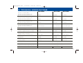
5. TECHNICAL SPECIFICATIONS
R4100A
R2180A
Rated Power Output (RMS)
All channels driven simultaneously
@ 13.8 V into 4 Ohms (THD<0.1%)
R2100A
4x85W
2x185W
2x10⁵W
Rated Power Output (RMS)
All channels driven simultaneously
@ 13.8 V into 4 Ohms (THD<1%)
4x95W
2x190W
2x110W
Rated Power Output (RMS)
All channels driven simultaneously
@ 13.8 V into 2 Ohms (THD<1%)
4x140W
2x310W
2x150W
Rated Power Output (RMS)
All channels driven simultaneously
@ 13.8 V into 4 Ohms (THD<1%)
2x280W Bridged
1x610W Bridged
1x300W Bridged
Damping Factor @ 4 Ohms Load All Channels
> 200
> 200
> 200
Signal-to-Noise Ratio (A-Filter Weighted)
All Channels @ full rated power output
> 95dB
> 95dB
> 95dB
Frequency Response (-3dB)
Operation Mode set to FULL,
All Channels driven simultaneously
10Hz - 40kHz
10Hz - 40kHz
10Hz - 40kHz
Channel Separation
All Channels
> 55dB
> 55dB
> 55dB
Input Sensitivity
All channel Pairs
0.2V - 9V
0.2V - 9V
0.2V - 9V
Integrated Cross-Over/Filtering
Slope Rates
12 dB/Octave High- & Lowpass
Highpass Cross-Over Frequency Range
Lowpass Cross-Over Frequency Range
continuously variable 10 - 400 Hz
continuously variable 30 - 400 Hz
Fuses
Dimensions (W x H x D)
3 x 25 A
384 x 65 x 265 mm
3x25A
405 x 65 x 265 mm
2x20A
292 x 65 x 265 mm
29
R4100A_Manual 2002-
30
25.02.2002
16:36 Uhr
Seite 30
R4100A_Manual 2002-
25.02.2002
16:36 Uhr
Seite 31
6. WARRANTY
Thank you for purchasing this RODEK R680A amplifier. It is advisable to keep the original packing material for future transporting of the
product. Please read the warranty specifications below carefully.
Should your RODEK product require warranty service, please return
it to the retailer from whom it was purchased, or the distributor in your
country. Please do not send any product to RODEK Inc. U.S.A. Should
you have difficulty in finding an authorized RODEK service center, details are available from your local distributor or from the ACR address
below.
The RODEK amplifier listed below is fully warranted against defective materials or workmanship for a period of TWO YEARS from date
of purchase. Warranty work will not be carried out unless this warranty
certificate is presented fully completed with model, serial number,
purchaser's address, purchasing date and dealer stamp together with
the original sales slip!
WARRANTY LIMITATIONS
This warranty does not cover any damage due to:
1. Improper installation, incorrect audio or mains connection(s).
2. Exposure to excessive humidity, fluids, sun rays or excessive
dirt or dust.
3. Accidents or abuse
4. Unauthorized repair attempts and modifications not explicitly authorized by the manufacturer.
This warranty is limited to the repair or the replacement of the defective product at the manufacturer's option and does not include any
other form of damage, whether incidental, consequential or otherwise. The warranty does not cover any transport costs or damages
caused by transport or shipment of the product.
GARANTIEBESTIMMUNGEN
Vielen Dank, dass Sie sich zum Kauf eines RODEK R680A Verstärkers entschlossen haben. Wir möchten Sie bitten, die Originalverpackung für einen allfälligen Transport aufzuheben und die untenstehenden Garantie-Bestimmungen genau durchzulesen.
Sollten Sie für Ihren Verstärker Garantie-Leistungen beanspruchen,
wenden Sie sich bitte direkt an den Händler, bei dem Sie das Gerät
gekauft haben. Bitte senden Sie keine Geräte an RODEK Inc. U.S.A.
Bei Schwierigkeiten, ein geeignetes RODEK Service-Center zu finden, erhalten Sie bei Ihrem jeweiligen Landes-Vertrieb weitere Informationen.
Der Hersteller gewährleistet auf diesen RODEK-Verstärker für den
Fall von Material- oder Herstellungsfehlern ZWEI JAHRE Garantie.
Garantie-Ansprüche können nur mit einer korrekt und vollständig
ausgefüllten Garantie-Karte und dem Original-Kaufbeleg geltend
gemacht werden.
GARANTIE-EINSCHRÄNKUNGEN
Nicht unter Garantie fallen Schäden infolge von:
1. unsachgemäßem Einbau oder inkorrekten Audio- oder Stromanschlüssen.
2. schädlichen Einwirkungen von übermäßiger Feuchtigkeit,
Flüssigkeiten, Hitze und übermäßiger Verschmutzung.
3. mechanischer Beschädigung durch Unfall, Fall oder Stoss.
4. Schäden durch nicht autorisierte Reparaturversuche oder nicht
durch den Hersteller ausdrücklich autorisierte Modifikationen.
Die Garantie dieses Produkts bleibt in jedem Fall auf die Reparatur
bzw. den Ersatz (Entscheidung beim Hersteller) des jeweiligen RODEK-Produkts beschränkt. Schäden durch unsachgemäße Verpackung
oder Transportschäden sind durch diese Garantie nicht gedeckt. Jeder über diese Garantie-Erklärung hinausgehende Anspruch und jede
Haftung für direkte oder indirekte Folgeschäden werden ausdrücklich abgelehnt.
31
R4100A_Manual 2002-
25.02.2002
16:36 Uhr
Seite 32
4.
R680i Trouble
Shooting Guide
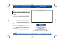
WARRANTY
CERTIFICATE
Model:
POWER AMPLIFIER RODEK R2180A
POWER AMPLIFIER RODEK R2100A
POWER AMPLIFIER RODEK R4100A
nth s
Lim ite d W arr an ty : 24 Mo
Dealer's address & stamp
Serial Number:
Date of purchase:
Your name:
Your address:
City:
State:
ZIP or Postal Code:
Country:
Exclusive distribution for Europe and Asia
Your phone number:
ACR, Brändli & Vögeli AG
Bohrturmweg 1, CH-5330 Zurzach , Switzerland
Phone: +41 (0)56 - 269 64 64, Fax: +41 (0)56 - 269 64 65
1 2 3 0 0 E D I S O N WAY · G A R D E N G R O V E · C A 9 2 8 4 1 U .
S.
A.