1
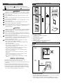
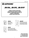
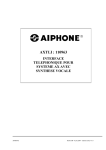
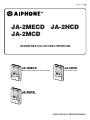
834571 1004 B
JA-2MECD JA-2HCD
JA-2MCD
HANDSFREE COLOR VIDEO INTERCOM
JA-2MECD
JA-2HCD
Master monitor station(with Picture memory)
Sub monitor station
JA-2MCD
Master monitor station
INSTALLATION & OPERATION MANUAL
1
PRECAUTIONS
General Prohibitions
Prohibitions to dismantle the unit
Prohibitions to subject the unit to water
PACKAGE CONTENTS
1
General Precautions
2
WARNING
(Negligence could result in death or serious injury to people)
1. High voltage is present internally. Do not open the case. Electric
shock could result.
2. Do not dismantle or alter the unit. Fire or electric shock could
result.
3. Do not connect the unit with any non-specified power source. Fire
or electric shock could result.
4. Keep the unit away from water or any other liquid. Fire or electric
shock could result.
5. Do not put any metal into the unit through the openings. Fire,
electric shock, or unit trouble could result.
6. When existing chime wires are used, it is possible that they contain
AC voltage. Electric shock or unit damage could result. Ask a
qualified technician.
JA-2MECD
4
3
5
JA-2MCD
6
CAUTION
(Negligence could result in injury to people or damage to property)
1. Do not put anything on or cover the unit with cloth, etc. Fire or
unit trouble could result.
2. In case of electrical storms, unplug the unit from AC outlet. If not,
fire or electric shock could result. (If AC cord is not seen, turn off
the Power switch on the left side.)
3. If LCD is punctured, do not allow contact with the liquid crystal
inside. Inflammation could result. If necessary, gargle your mouth
and clean your eyes or skin with clear water for at least 15
minutes, and consult your doctor.
4. Do not install the unit in any of the following locations.Fire,
electric shock,or unit trouble could result.
* Places under direct sunlight, or near heating equipment that
varies in temperature.
* Places subject to dust, oil, chemicals,
* Places subject to moisture and humidity extremes, such as
bathroom,cellar, greenhouse, etc.
* Places where the temperature is quite low, such as inside a
refrigerated areaor in front of air-conditioner.
* Where noise generating devices such as dimmer switches,
invertor electrical products.
* Places subject to steam or smoke (near heating or cooking
surfaces).
* Where noise generating devices such as dimmer switches,
invertor electrical appliances, are closeby.
* Places subject to steam or smoke (near heating or cooking
surfaces).
JA-2HCD
Package contents
1
2
3
4
5
6
JA-2MECD, JA-2MCD or JA-2HCD
Packet of screws
Optional function connector
Door release connector
Mounting bracket
INSTALLAITON & OPERATION MANUAL
2
2-1
INSTALLATION
[1]
GENERAL PRECAUTIONS
1. The unit is for domestic use only. Do not use outdoors.
2. When power fails, the unit becomes inoperative.
3. The unit is for wall-mount use only. For desktop applications, use
desk stand.
4. In areas where broadcasting station antennas are close by, the
intercom system may be affected by radio frequency interference.
5. If the phone is operated near OA equipment, Radio or TV, they
interactively influence by radio frequency interference. Carefully
select both locations for installation and operation.
[2]
50mm+
(2")
Installation locations
1. Do not mount the inside monitor station in areas directly facing bright
lighting. Viewing image may be affected.
2. On the left side, the monitor station has a POWER switch. Secure a
space of 50mm(2") or more between the unit and a wall or furniture.
-2-
2-2
Wiring distance
JA-2MECD
JA-2MCD
JA-DAC
JA-2HCD
B1, B2
2
JA-DAC
B1, B2
B1, B2
B1, B2
JA-2SD
JA-2SD
JA-2HCD
JA-2MECD
JA-2MCD
0.65mm
50m
50m
50m
5m
50m
50m
A
A'
B
C
D
E
4
4
2
JA-2HCD
1.0mm
100m
100m
100m
10m
100m
100m
22AWG
165'
165'
165'
16'
245'
165'
18AWG
330'
330'
330'
33'
330'
330'
JA-2HCD
3
4
JA-DAC
MOUNTING
2
[3]
B1, B2
JA-2SD
JA-2SD
4
JA-2HCD
[1]
[2]
46mm
(1-13/16")
JA-2MECD
JA-2MCD
JA-2HCD
JA-2HCD
JA-2MECD
JA-2MCD
JA-DAC
2
83.5mm
(3-5/16")
4
JA-2SD
4
B1, B2
JA-2SD
8
Wiring method
Wire the inside stations in a station-to-station (daisy-chained) manner.
2-3
1
(x2)
JA-2MECD
JA-2MCD
JA-DAC
JA-D
A1
A2
A1
A2
A1
A2
A1
A2
9mm
(3/8")
JA-2HCD
B1
B2
+
-
2
B1 B1
B2 B2
+
-
120
3.
120
Cable
1. Use 2-conductor, non-shielded cable. Vinyl-jacketed cable with
PE(polyethylene) insulated wires is recommended.
2. Never use loose wires, shielded wire, twisted pairs, or coaxial cable.
3. When using existing cable with multiple wires, terminate both ends of
each unused pair with a 120 ohm resistor.
PS-2420
PS-2420S
PS-2420UL
PS-2420DIN
PS-2410DIN
[2] [3]
2-4
D1
A
83.5mm
(3-5/16")
D2
A'
[4]
JA-DAC
JA-D
JA-DAC
E
M
PS
C
JA-2MECD
JA-2MCD
D
Mounting
IER-2
[1] Screw (x4)
[2] Mounting bracket
[3] Two-gang box
• Provide a box DEEP enough to accommodate all cables incl. options.
[4] DIN rail
1. Depress UNLOCK button (to unlock or to insert the wire securely).
2. Insert the cable into terminal.
3. When GANG BOX is not provided, the cable can be surface run from
the top or bottom of the unit. Cut open the cable inlet hole to run
wires to the back of the unit.
PS-2420
PS-2410
S1
B
ADAP
JAW-AZ
JA-2HCD
JA-2SD
CAM
S2
JA-2HCD
JA-2SD
CAM : motion detect sensor or sensor / camera
-3-
4
WIRING
[1] JA-2MECD
[5]
JA-2MCD
PS-2420DIN
230V AC
[6] OP
N
L
2
EL-9S
IN 230V~ 50/60Hz
NL
2A - +
NP
PT
24V DC2A -+
PS-2420
2
[3]
A1 A2
EL-9S
PT
B1
B2
2
A1
A2
NP
A1
JA-DAC
A2
C1
[4]
C2
A1 A2
C1
C2
AIPHO
NE
MK-DV
F
S
2
S
SUBMASTER
DOOR-1
L1
L1
L2
L2
24V DC
2A
100V-240V~
50/60Hz
DOOR-2
PS-2410DIN
ADAPTER-1
230V AC
N
ADAPTER-2
CALL EXT
SPEAKER
NP
JA-DAC
-
NP
OPTION
AIPHO
NE
MK-DV
F
+
L
DC24V
+ -
IN 230V~ 50/60Hz
NL
1A - +
-
JA-D
24V DC1A
4
+
DC 24V
JAW-AZ
[9]
2
[2]
+
2
Motion detect
Camera
-
P
+
NP
Adaptor
JAW-AZ
[8]
2
Motion detect
Camera
NP
OP IER-2
1
E
[10]
SUB OUT
2
[8]
NP
-
OP
ON - OFF
JA-2MECD JA-2HCD
JA-2SD
ON
4
RY-3DL
PT
SUB IN
A
B1
B2
B1
B2
Adaptor
[7]
[2] JA-2SD
JA-2HCD
L1
C1 b1
L1 b2
b3
L2 L
C2
D1
L2 E
D2
JA-2MECD
[2]
#1
+
-
OG(b1)
YE(b2)
#2
BR(L1)
RD(L1)
OG(L2)
YE(L2)
[2] JA-2SD
JA-2HCD
[8]
DC24V
+
-
+
-
PS24
B1
B2
B1
B2
SUB IN
A
SUB OUT
[8]
OG: Orange
YE: Yellow
BR: Brown
RD: Red
-4-
JA-2MECD JA-2HCD
JA-2SD
OFF
ON - OFF
JA-2HCD
JA-2SD
ON
4-1
5
5-1
Wiring
Insert the wire into the terminal securely.
[1] Master monitor station JA-2MECD, JA-2MCD
[2] Sub monitor station JA-2HCD or Sub master station JA-2SD
(Audio only)
[3] Video door station JA-DAC
[4] Video or audio door station JA-DAC, JA-D
[5] Power supply +, – (DC 24V)
[6] OPTION Door release EL-9S (12V AC 0.35A) or equivalent
Requires a separate AC transformer. Separately run a cable
for each audio/video and door release.
[7] OPTION Call extension speaker IER-2
[8] Impedance matching switch
Terminate the last sub station, putting SW to A position.
Otherwise both video image and audio quality will be
affected.
[9] Adaptor for Motion Detect Sensor & Camera (SOP available
in USA only)
[10] OPTION Use RY-3DL adaptor to connect 1~2 door releases
of other manufacture, rated more than EL-9S.
NP: Non-polarized P: Polarized
NAMES
JA-2MECD
[7]
[1]
DOOR
1
[8]
2
[9]
[3]
[4]
MONITOR
SET
SET SAVE
PLAY
CALL
[5]
JA-2MECD
BRIGHT
L
H
REC
[2]
[6]
TALK
[10]
[11]
[12]
[13]
[14]
[15]
4-2
JA-2MECD
JA-2MCD
VIDEO OUT
#1 #2
#1
(PR)
E
(BL)
+
B1
[1]
B2
[2]
(GR)
(YE)
b1
V-
(OG)
A2
V+
(RD)
(BR)
C1
C2
C1
C2
S
[4]
DC24V
S
[5]
#2
L1
(BR)
(RD)
EL-9S
1
JA-2HCD
#1
L1
L2
(OG)
(YE)
[16]
[19]
[17]
[18]
Names (JA-2MECD)
[1] LCD (4 inch color)
[2] POWER Switch
[3] Speaker for chime & internal pre-tone/voice
[4] ABSENCE SET button
[5] PLAY button
[6] REC button
[7] Mic.
[8] Door call-in LED (red)
[9] PanTilt control pad
[10] MONITOR button
[11] Screen brightness control
[12] ROOM CALL button
[13] Transmit LED (red)
[14] Door release button
[15] TALK button
[16] VIDEO output (JA-2MECD only)
[17] Camera white light auto ON/OFF switch
[18] Active door call-in selector switch 1, 2 & 1&2
[19] Chime TONE volume control
A1
[3]
DOOR CALL TONE
1 2 1&2
A1
A2
b2
LIGHT
OFF AUTO
EL-9S
2
L2
Options
1 Foot talk switch
Connect foot call switch (locally available) to PURPLE, BLUE
wires (dry contact closure).
2 Manual press-to-talk restriction
Short between PURPLE and GREEN wires to prevent manual
TALK button operation.
3 Local door release
Connects a local door release which has bigger contact
capacity than EL-9S. For two door releases, use an RY-3DL
adaptor (See Wiring diagram of RY-3DL on Page 4).
4 Video output to video apparatus, video printer, etc. (NTSC,
1Vp-p/75 Ω).
5 Two EL-9S door releases
Connect an EL-9S to BROWN & RED leads, which
corresponds to Door station 1. And, for door station 2, connect
the other EL-9S to ORANGE & YELLOW wires.
• For JA-2HCD, only the functions No.1 & 2 are available.
• Cut off unused wires to prevent shorting.
-5-
5-2
6
INITIAL PICTURE MEMORY SETTING
JA-2MCD/JA-2HCD
[5]
[1]
DOOR
1
2
[6]
12/OCT/03
12/OCT/03
15:30
15:30
12/OCT/03
12/OCT/03
15:30
15:30
1
2
2
1
[7]
10/OCT/03
[3]
[4]
CALL
JA-2MCD
BRIGHT
L
H
[2]
TALK
20:25
10/OCT/03
09/OCT/03
MONITOR
SET
3
[8]
[9]
[10]
[11]
[12]
4
09:48
20:03
5
PLAY
SET
[1]
[13]
REC
2 Sec. +
VIDEO OUT
LIGHT
OFF AUTO
DOOR CALL TONE
1 2 1&2
[2]
[14]
[17]
[15]
[16]
1/JAN/04
0:00
1/JAN/04
0:00
1/JAN/04
0:00
1/JAN/04
0:00
1/JAN/04
PLAY
Names (JA-2MCD / JA-2HCD)
[1] LCD (4 inch color)
[2] POWER Switch
[3] Speaker for chime & internal pre-tone/voice
[4] Motion detect camera SET button (JA-2MCD only)
[5] Mic.
[6] Door call-in LED (red)
[7] PanTilt control pad
[8] MONITOR button
[9] Screen brightness control
[10] ROOM CALL button
[11] Transmit LED (red)
[12] DOOR RELEASE button
[13] TALK button
[14] VIDEO output (JA-2MCD only)
[15] Camera white light auto ON/OFF switch (JA-2MCD only)
[16] Active door call-in selector switch
[17] Chime TONE volume control
SET
[3]
REC
1/ JAN/ 04
D ay
Month
PLAY
0:00
Year
Ti me mi n
SET
REC
16 (4-frame in one picture)
[4]
16 (4-FRAME IN
ONE PICTURE)
16
32
60
SET
[5]
SET
PLAY
PLAY
REC
REC
-6-
0:00
7-3
Initial picture memory setting
Before use, be sure to program in the following manner:
1. Place the unit in SET mode. Press SET button and hold down
for more than 2 seconds. Both PLAY & REC buttons start
flashing.
2. Choose on-screen DATE location. As desired, move up with
PLAY button, and move down with REC button. Press SET
button to select. Next, “2003” flashes.
3. Set time in the order of; (1) Year, (2) Month, (3) Day, (4) Hour,
and (5) Minute.
1/JAN/04 0:00
4. Choose PICTURE MEMORY mode. Move cursor to the mode
desired. (Most recommended is 16 picture, 4-frame). Press SET
button to select.
5. When finished, press TALK button, or programming will
terminate in approx. 2-1/2 minutes. All the buttons are no
longer lit to indicate unit is in standby mode.
Notes:
• When changing PICTURE MEMORY mode, all the previously
saved pictures will be erased. Never change if the saved pictures
MUST be kept.
• It is not possible to go back and partially reprogram DATE
location or TIME. Go back to initial SET mode.
• If setting has ended incompletely within approx. 2-1/2 minutes,
go back to initial SET mode.
7
7-1
[1]
MONITOR
[2]
JA-DAC 1
MONITOR
[3]
MONITOR
[4]
JA-DAC 2
Monitor a door station
1. Momentarily press MONITOR button.
2. Video monitor turns on image of DOOR 1.
3. Press MONITOR button again to switch to DOOR 2.
4. Press MONITOR button to end monitoring.
Notes:
• Inside audio cannot be heard at door station.
• Press TALK button to establish communication with door
station.
• The image automatically turns off in approx. 30 sec.
• When DOOR2 is audio-only type (JA-D), it is skipped while
monitoring and audio door cannot be monitored.
OPERATIONS
7-4
[1]
[2]
DOOR
1
2
[3]
[4]
Pan and tilt the door station camera
The monitor station is equipped with Aiphone's exclusive Panand-Tilt control pad. When the video door station is on, press on
each edge of pad to move the camera up down and right left.
7-2
[1]
Answering a door call (AUTO mode)
The station is initially set to AUTO voice switch activation.
1. Momentarily press CALL button.
2. Chime tone sounds, and the monitor turns on with caller’s
image. Door call-in LED 1 or 2 is lit.
3. Press TALK button momentarily and reply handsfree.
4. When finished, press TALK button once to turn off.
Timer; Call-in, 30 sec. Communication, 1 min. (approx.). Press
TALK button to turm back on (if within 30 sec.)
[2]
Instant voice calling for family use
1. Momentarily press CALL button.
2. When chime sounds, the monitor turns on with the image of
the caller. Sound from the entry area is heard through the
speaker of the inside station(s).
Note: Not available on JA-D door station.
-7-
7-5
[1]
7-7
[2]
[1]
[2]
DOOR
CALL
1
2
[3]
[4]
[5]
[3]
Answering a door call (MANUAL Press to Talk mode)
1. Momentarily press CALL button.
2. Chime tone sounds, and the visitor’s voice is heard. The
monitor turns on with caller’s image. Door call-in LED 1 or 2
is lit.
3. Depress and hold down TALK button for 1 second or more.
4. To transmit, talk while pressing TALK button, and release
TALK button to listen.
5. When finished, press TALK button once to turn off.
Timer; Call-in, 30 sec. Communication, 1 min. (approx.). Press
TALK button to turm back on (if within 30 sec.)
Room-to-room communication
1. Press CALL button once. Call by voice to the other inside
station(s).
2. The called station(s) sounds a pre-tone and voice.
3. Press TALK button once, and reply handsfree.
4. When finished, press TALK button once to turn off.
Note: Communication is approx. 1 minute.
7-8
[1]
7-6
[1]
[4]
[2]
CALL
[2]
[3]
Activating door release
1. Press and hold down DOOR RELEASE button.
2. The door release mechanism will be activated while the button
is pressed.
[4]
Transfer a door call
1. While viewing the visitor, press ROOM CALL button. After
pre-tone, call a person desired by voice.
2. At the called stations, after pre-tone, image and audio of door
will be activated.
3. At a responding station press TALK button to reply. When
finished, press TALK at either station.
4. Second person presses TALK once to connect to the door
station. Communicate with visitor. To return to standby, press
TALK button.
-8-
8
8-1
8-3
PICTURE MEMORY
[1]
[2]
[3]
1sec
16-picture, 4-frame
1
2
3
4
4
PLAY
200 1
5 sec
1 sec
5sec
SE P
1
3
2
15: 30
REC
PLAY
9 sec
1 / JAN / 01
9sec
1
15:30
13sec
13 sec
1 / JAN / 01
[2]
15:30
REC
TALK
PLAY
Automatic picture memory
When video door station calls in, picture memory is automatically
activated (JA-2MECD only). REC button is steadily lit to indicate.
Put JA-2MECD in Surveillance-SET mode to receive image from
Motion-detection camera.
Notes:
• Automatic picture memory is a built-in feature, and cannot be
turned off.
• Auto picture memory is not effective;
- During video monitoring.
- For approx. 4 sec. after ending replay.
- For approx. 15 sec. after the previous save.
REC
Replay
1. Press PLAY button. The latest picture is displayed.
2. Press PLAY button repeatedly to view each previous picture
that has been saved. The screen with
means the last page.
Press REC button to view retroactively.
3. In replay of 16 (4 frame) pictures, press REC button to view
each frame picture in full screen.
4. To end, press TALK button once, or it will automatically turn
off in approx. 1 minute.
8-2
[1]
[4]
[2]
8-4
[1]
[2]
M5
MONITOR
REC
20 01
SET
SE P
1
15 :3 0
SET
Manual picture memory
1. Press Monitor button to display the image on the monitor.
2. Press REC button. The REC button is lit to indicate the image
is being saved.
Notes:
• When door calls in, an auto-saved image will be overwritten if
saved manually.
• Manually picture memory is a full-screen image regardless of
the initial program mode.
M5
12 / OCT / 03 15:30
M5
12 / OCT / 03 15:30
JA-2MECD
SET
[3]
12/OCT/03 16:40
Save in memory
1 (During replay) Press SET button. The image on the screen is
stored in memory. On the screen, M5 indicates the 5th image
(Max. 8 per system).
Note:The image stored in memory will not be overwritten
during another operation. To erase, proceed to ERASE
operation.
2 To release (During replay) While the image is on the screen,
press SET button. The “M” goes out, and memory is cleared.
Note:The image in memory will not be erased, but overwritten
(erased) when new picture is saved.
3 The “on-screen” FULL indicates it is the 9th picture whose
memory is void.
Note:When one frame picture is memorized, all four frame
pictures are memorized as one picture.
-9-
8-5
9-2
[1]
SET
[2]
PLAY
14 / OCT / 03 13:30
12 / OCT / 03 14:30
PLAY
2/5
SET
1 / S E P /0 1
REC
20 01
SE P
1
15 :3 0
1 4 :3 0
2/5
Number Total
[3] [4]
JA-2MECD
Erase
While replaying
Display the picture to be erased on monitor. Holding down SET
button, press “REC” for 2 sec. Next picture appears. Release
“REC” button.
Note:
This also applies to erasing saved pictures. The picture, once
erased, cannot be restored. One picture in 4-frame mode cannot
be erased, but all four at once.
To erase all the pictures
Return to initial picture save mode, and change to any other
mode (16 in 4-frame, 32, or 60).
9
9-1
[5]
[6]
:1
rrrrr
Prrr Prr :2
Prr
SURVEILLANCE-SET
[1]
Surveillance / Absence-SET
1. The flashing SET button indicates visitor(s) called during your
absence.
2. Number of visitors is shown on the screen. Example: 2/5
(2nd/# total visits).
3. When motion detection surveillance camera is installed: After 1
minute, the camera is placed in surveillance mode. When
motion detector is activated, inside monitor turns on and a
unique alarm sounds and saves the image.
4. At approx. 1 second after activation, a picture will be taken. If
recording mode is set in 4-frame mode, pictures will be taken
in 4-second intervals, starting at 1 second (1, 5, 9, and 13
seconds after activation).
5. Both alarm sound and image will automatically time out in
approx. 30 seconds. Alarm may be silenced.
6. Press TALK button. The alarm stops. Press TALK again to turn
off image. Communication is not available.
Notes:
• To change setting on camera and motion detector, refer to
instruction manual(s) for those components.
• Automatic update
When capacity is exceeded, the saved pictures will be erased
from the oldest one first, with each new one replacing the oldest
(including non-replayed images).
Note: The image can be saved in memory if needed.
[2]
SET
JA-2MECD
JA-2MECD
Surveillance-SET (Absence-SET)
Press “SET” button once. The button is lit in red. The system goes
into “Absence-SET” mode or Motion-detection Camera-SET”
mode.
Press “SET” button to reset. The button is no longer lit.
Notes:
Press and hold “SET” button for 2 seconds or more to go into
INITIAL PROGRAM mode.
When “SET” button is flashing, view newly recorded pictures
first by pressing PLAY button.
When the button is steadily lit, press “SET” to return to normal.
- 10 -
10-3
10 MULTI-MODE OPERATIONS
10-1
ENTRANCE
1
2
14 / OCT / 01 13:30
ENTRANCE
MONITOR
SET
VIDEO OUT
ROOM
PLAY
BRIGHTNESS
DARK
BRIGHTNESS
RELEASE
REC
TALK
1 2 / OC T / 0 1 1 4 :3 0
JA-2MECD
During replay
During replay; When a door station has called or camera has
been activated, it is indicated by an “on-screen” mark, and its callin image is viewed and saved automatically. (Replay mode is
ended.) View visitor and communicate.
Notes:
• Room call-in has no on-screen mark shown. The replay mode is
terminated.
• When initiating replay, auto-picture memory (for door call-in) is
not effective for approx. 2 seconds.
NTSC
14 / OCT / 01 13:30
To send video signal to AV equipment
The image on the monitor is printable via composite VIDEO OUT
terminal, connected to a Video printer, etc. (Select a model which
handles NTSC signals).
10-2
11
[1]
Technical Precautions
• Operating temperature: 0°C ~ 40°C (+32°F ~ +104°F).
• Image may vary when Door release button is held down. This is
not a malfunction.
• Cleaning: Clean the units with a soft cloth dampened with
neutral household cleanser. Do not use any abrasive cleaner or
cloth.
• Door station is weather-resistant. But do not spray high-pressure
water on door station directly. Unit trouble could result.
• In case of system malfunction, turn off the power switch of
master station. If this doesn’t solve the problem, disconnect DC
power and contact qualified technician.
ENTRANCE
1
PLAY
2
SET
ENTRANCE
MONITOR
SET
REC
ROOM
REPLAY
BRIGHTNESS
DARK
BRIGHTNESS
RELEASE
REC
TALK
JA-2MECD
[2]
SET
SET
PLAY
TECHNICAL PRECAUTIONS
SET
12
SET
SPECIFICATIONS
Specifications
• Power source:
• Consumption:
When PLAY & REC buttons are both lit
1. When the system has not been used for months or turned off
for more than 30 minutes after power failure, etc., PLAY &
REC buttons are lit. In this case, press SET button. Two
buttons lights turn off. Set PICTURE MEMORY MODE again.
2. If SET button is still lit or flashing, turn it off by following
these steps: Release SURVEILLANCE-SET mode (Page10).
SET flashes
Press PLAY
SET lit
Press SET
SET
light turns off
Notes:
• When changing PICTURE MEMORY MODE, all the pictures
previously saved will be erased.
•
•
•
•
•
•
•
- 11 -
DC 24V
(MAX) 750mA (JA-2MECD)
(MAX) 680mA (JA-2MCD).
(MAX) 290mA(JA-2HCD).
Calling:
Chime & image, Approx. 30 sec.
Communication: AUTO Handsfree voice activation
MANUAL Press to talk, release to listen
Video-monitor:
4 inch direct view TFT color LCD
Scanning line:
525 lines
Door release contact:
AC 12V, 0.35A (dry closure contact L, L).
Run a separate cable for audio/video signal
and door release contact.
Dimensions:
210H x 160W x 42D(mm).
8-1/4”H x 6-5/16”W x 1-5/8”D.
Weight:
820g (1.81 lbs.) (aprox.) (JA-2MECD)
770g(1.70 lbs.) (approx.) (JA-2MCD)
730g (1.61 lbs.) (approx.) (JA-2HCD)
WARRANTY
Aiphone warrants its products to be free from defects of material and
workmanship under normal use and service for a period of two years after
delivery to the ultimate user and will repair free of charge or replace at no
charge, should it become defective upon which examination shall disclose to
be defective and under warranty. Aiphone reserves unto itself the sole right
to make the final decision whether there is a defect in materials and/or
workmanship; and whether or not the product is within the warranty. This
warranty shall not apply to any Aiphone product which has been subject to
misuse, neglect, accident, or to use in violation of instructions furnished, nor
extended to units which have been repaired or altered outside of the factory.
This warranty does not cover batteries or damage caused by batteries used in
connection with the unit. This warranty covers bench repairs only, and any
repairs must be made at the shop or place designated in writing by Aiphone.
Aiphone will not be responsible for any costs incurred involving on site
service calls.
This equipment has been tested and found to comply with the limits for a
Class B digital device, pursuant to Part 15 of the FCC Rules. These limits are
designed to provide reasonable protection against harmful interference in a
residential installation. This equipment generates, uses, and can radiate radio
frequency energy, and if not installed and used in accordance with the
instructions, may cause harmful interference to radio communications.
However, there is no guarantee that interference will not occur in a particular
installation. If this equipment does cause harmful interference to radio or
television reception, which can be determined by turning the equipment off
and on, the user is encouraged to try to correct the interference by one or
more of the following measures: • Reorient or relocate the receiving antenna.
• Connect the equipment into an outlet on a circuit different from that to
which the receiver is connected. Increase the separation between the
equipment and receiver. • Consult the dealer or an experienced radio/TV
technician for help.
http://www.aiphone.com/
AIPHONE CO., LTD., NAGOYA, JAPAN
AIPHONE CORPORATION, BELLEVUE, WA, USA
AIPHONE S.A., WISSOUS, CEDEX, FRANCE
Printed in Japan
- 12 -