1
Sequoia
Model 2160
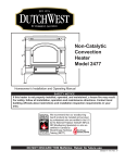
Homeowner’s Installation and Operating Manual
SAFETY NOTICE
If this Sequoia is not properly installed, operated, and maintained, a
house fire may result. For safety, follow all installation, operation and
maintenance directions. Contact local building officials about restrictions and installation inspection requirements in your area.
CFM Specialty Home Products
410 Admiral Blvd. • Mississauga, Ontario, Canada L5T 2N6 • 905-670-7777
www.majesticproducts.com • www.vermontcastings.com
DO NOT DISCARD THIS MANUAL: Retain for future use
2001049 4/04 Rev. 4
Dutchwest Sequoia
Welcome
Congratulations on your choice of a Dutchwest Sequoia. With this purchase, you have made a commitment to make
the hearth a place of warmth, beauty and comfort in your home. At CFM Specialty Home Products, we share that joy
and appreciation for the hearth, and we show it in all our cast iron stoves and fireplaces.
As you become acquainted with your new stove or fireplace, you will find that its visual appearance is matched by its
functionality, due to cast iron’s unique ability to absorb and radiate heat.
Also, Dutchwest products are among the cleanest-burning wood stoves and fireplaces available today. And as an
owner of a Dutchwest stove or fireplace, you are making a strong statement for pollution-free energy. But clean
burning depends on both the manufacturer and the operator. Please read this manual carefully to understand how to
operate your stove or fireplace properly.
At CFM Specialty Home Products, we are equally committed to your satisfaction as a customer. That is why we
maintain an exclusive network of the finest dealers in the industry. These dealers are chosen for their expertise and
dedication to customer service. They are factory-trained to know the most minute detail of every Dutchwest product.
Feel free to contact your local Authorized Dutchwest Dealer anytime you have a particular question about your stove
or its performance.
Be assured that your cast iron Dutchwest stove or fireplace has been made with the utmost care and will provide you
with many years of service.
This manual contains valuable instructions on the installation and operation of your Dutchwest stove or fireplace. It
also contains useful information on maintenance and assembly of this product. We urge you to read the manual
thoroughly and to keep this manual as a reference.
Sincerely,
All of us at Dutchwest
Table of Contents
Accessories
Specifications ................................. 3
#6061 Rear Heat Shield
Installation ...................................... 4
#6062 Bottom Heat Shield
Assembly ...................................... 16
#0134 Fire Screen
Operation ..................................... 18
Maintenance ................................. 23
Warranty ....................................... 33
Proposition 65 Warning: Fuels used in gas,
woodburning or oil fired appliances, and the products
of combustion of such fuels, contain chemicals
known to the State of California to cause cancer,
birth defects and other reproductive harm.
California Health & Safety Code Sec. 25249.6
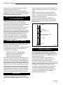
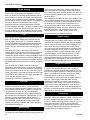
This manual describes the installation and operation of the Sequoia Model 2160 catalytic-equipped wood heater. This heater meets the U.S.
Environmental Protection Agency’s emission limits for wood heaters sold after July 1, 1990. Under specific test conditions this heater has been
shown to deliver heat at a rate ranging from 10,400 to 31,700 Btu’s/Hr. A Sequoia equipped with an 8” (200mm) flue collar also burns coal. Coalburning in the Sequoia is not allowed with the 6” (150mm) flue collar. In addition, the catalytic combustor must be removed before burning coal. In
addition to directions on installation and operation, this manual includes directions on maintenance and assembly.
We recommend that you hire a professional solid fuel stove installer to install your stove, or to advise you on the installation should you attempt to
install it yourself.
The Sequoia has been tested and is listed by Warnock Hersey of Middleton, Wisconsin. The test standards for the Sequoia equipped with a 8”
(200mm) flue collar are ANSI/UL 1482 and ANSI/UL 737 for the United States and CAN/CSA-B366.2 for Canada. The Sequoia equipped with a 6”
(150mm) flue collar is not tested to ANSI/UL 737 and should not be used in conjunction with fireplace screen. The Sequoia is not listed for
installation in mobile homes.
2
2001049
Dutchwest Sequoia
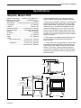
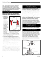
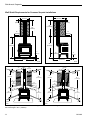
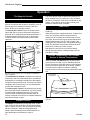
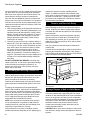
Specifications
Sequoia, Model 2160
Range of heat output ...... 10,400 to 31,700 Btu’s/hr.***
Maximum heat output .................. 50,000 Btu’s/hr.*****
Maximum burn time ........................................ 8 hours*
Area heated** .... 1,000-2,000 Square feet (65-130m2)
Log lengths ............................................. 23” (580mm)
Loading .................................................. Side or Front
Chimney Flue Size ............ 6” (150mm) or 8” (203mm)
Flue exit position ................... Reversible, Top or Rear
Weight .............................................. 540 lbs. (245kg.)
Air Control ................................................... 3 controls
Width ...................................................... 26” (660mm)
Depth ................................................... 15¹⁄₂” (395mm)
Height
w/6” standard legs .......... Top exit: 29¹⁄₂” (750mm)
...................................... Rear exit: 30¹⁄₂” (775mm)
w/Pedestal ...................... Top exit: 32³⁄₄” (835mm)
...................................... Rear exit: 33³⁄₄” (855mm)
* General guidelines only; may vary with fuel type,
moisture content, load size and installation variables.
**These values are based on operation in building-code
conforming homes under typical winter climate conditions in New England. If your home is of nonstandard
construction (e.g., unusually well-insulated, not insulated, built underground, etc.) or if you live in a more
severe or more temperate climate, these figures may
not apply. Since so many variables affect stove sizing,
consult your local dealer to determine realistic expectations for your home.
*** These values were obtained under specific laboratory test conditions using Douglas fir dimensional
lumber test fuel.
**** These values can vary depending on how the stove
is operated, the type and moisture content of the fuel
used, as well as the design, construction and climate
location of your home. Figures shown are based on
maximum fuel consumption obtained under laboratory
conditions using cordwood fuel and on average wood
stove efficiencies.
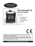
25"
(640mm)
22¹⁄₄"
(565mm)
25" (640 mm)
19" (480mm)
30"
(750mm)
Top of Collar,
Rear Exit
8" - 30¹⁄₂" (760mm)
6" - 30⁵⁄₈" (762mm)
Center of Collar,
Rear Exit
8" - 28" ( 710mm)
6" - 27³⁄₈" (695mm)
17¹⁄₂" (450mm)
25¹⁄₂" (650mm)
Fig. 1 Sequoia specifications.
2001049
3
Dutchwest Sequoia
Installation
SAFETY NOTICE: IF YOUR SEQUOIA HEATER IS
NOT PROPERLY INSTALLED, OPERATED AND
MAINTAINED, A HOUSE FIRE MAY RESULT. FOR
SAFETY, FOLLOW ALL INSTALLATION,
OPERATION AND MAINTENANCE DIRECTIONS.
CONTACT LOCAL BUILDING OFFICIALS ABOUT
RESTRICTIONS AND INSTALLATION INSPECTION
REQUIREMENTS IN YOUR AREA.
Chimney Types
Your Sequoia must be connected to a sound masonry
chimney that meets local codes, a relined masonry
chimney that meets local codes, or to an approved
prefabricated metal chimney. Whatever kind you use,
the chimney and chimney connector must be in good
condition and kept clean.
Before you begin the installation, review your plans to
confirm that:
• Your stove and chimney connector will be far enough
from combustible materials to meet all clearance
requirements.
• The floor protector is large enough and is constructed
properly to meet all requirements.
• You have obtained all necessary permits from local
authorities.
Your local building official is the final authority for
approving your installation as safe and for determining
that it meets local and state codes.
The metal label permanently attached to the back of the
stove indicates that it has been tested to current UL and
ULC standards, and gives the name of the testing
laboratory. Clearance and installation information is
also printed on the label. Local authorities generally will
accept the label as evidence that, when the stove is
installed according to the information on the label and
in this manual, the installation meets codes and can be
approved.
Codes vary in different areas, however. Before starting
the installation, review your plans with the local building
authority. Your local dealer can provide any additional
information needed.
For any unresolved questions about installation, refer to
the National Fire Protection Association’s publication
ANSI/NFPA 211-1988 Standard For Chimneys, Fireplaces, Vents and Solid Fuel Burning Appliances. In
Canada, the equivalent publication is CSA CAN-B365,
Installation Code for Solid Fuel Burning Appliances and
Equipment. These standards are the basis for many
national codes. They are nationally recognized and are
accepted by most local authorities. Your local dealer or
your local building official may have a copy of these
regulations.
Important: Failure to follow these installation instructions may result in a dangerous situation, including a
chimney or house fire. Follow all instructions exactly,
and do not allow makeshift compromises to endanger
property and personal safety.
Masonry Chimneys
If you use an existing masonry chimney, it must be
inspected to ensure safe condition before the stove is
installed. Your local professional chimney sweep,
building inspector, or fire department official will be
able either to make the inspection or to direct you to
someone who can.
An inspection of the chimney must confirm that it has a
lining. Do not use an unlined chimney. The chimney
should also be examined for cracks, loose mortar, other
signs of deterioration, and blockage. Repair any
defects before the chimney is used with your stove.
Unused openings in an existing masonry chimney must
be sealed with masonry to the thickness of the chimney
wall, and the chimney liner should be repaired. Openings sealed with pie plates or wallpaper are a hazard
and should be sealed with mortar or refractory cement.
In the event of a chimney fire, flames and smoke may
be forced out of these unused thimbles.
The chimney should be thoroughly cleaned before use.
A newly-built masonry chimney must conform to the
standards of your local building code or, in the absence
of a local code, to a recognized national code. Masonry chimneys must be lined, either with code-approved masonry or pre-cast refractory tiles, stainless
steel pipe, or a code-approved, “poured-in-place” liner.
The chimney’s clean-out door must seal tightly.
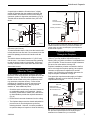
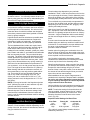
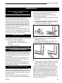
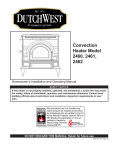
Prefabricated Double-Wall
Insulated Chimney
Tile Lined
Masonry
Chimney
ST241
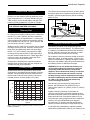
Fig. 2 If in sound condition and approved for use, either a
masonry or a prefabricated chimney may be used.
4
2001049
Dutchwest Sequoia
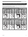
Prefabricated Chimneys
A prefabricated metal chimney must be one tested and
listed for use with solid-fuel burning appliances to the
High-Temperature (H.T.) chimney Standard UL-1031985 (2100°F.) for the United States, and High Temperature (650°C) Standard ULC S-629 for Canada.
DO NOT CONNECT THIS UNIT TO A CHIMNEY
FLUE SERVING ANOTHER APPLIANCE.
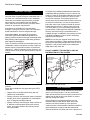
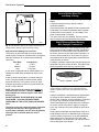
The chimney should extend at least 3’ (914mm) above
the highest point where it passes through the roof, and
at least 2’ (610mm) higher than any part of a building
within 10’ (3m).
0 To 10’
2’ Min.
3’
Min.
0 To 10’
2’ Min.
3’
Min.
Chimney Size
A Sequoia with an 8” (203mm) flue collar is approved
for venting into a masonry chimney with a nominal flue
size of 8” x 8” (203 x 203mm), and into a round flue
size of 8” (203mm). A Sequoia with a 6” (152mm) flue
collar is approved for venting into a masonry chimney
with a nominal flue size of 8” x 8” (203 x 203mm), and
into a round flue size of 6” (152mm).
Whatever the flue collar size, a Sequoia may be vented
into larger chimneys as well. However, chimneys with
larger liners and particularly those with liners larger
than 8” x 12” (203 x 305mm) may experience rapid
cooling of smoke and reduction in draft, especially if
they are located outside the home. These large chimneys may need to be insulated or have their flues
relined for proper stove performance.
Accessories to help make the connection between
stainless steel chimney liners and your Sequoia are
available through your local dealer.
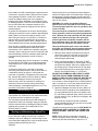
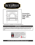
Chimney Height
Altitude affects chimney performance. Refer to the
chart below for suggested chimney heights at various
altitudes. Chimney height should be measured form
the flue collar to the top of the chimney. The recommended minimum chimney height is 16’ (4.9m).
25
Height
AC617
Fig. 4 The 2/3/10 rule for chimneys.
Chimney Connector Guidelines
The chimney connector is the single-wall pipe that
connects the stove to the chimney. The chimney itself
is a masonry or prefabricated structure that encloses
the flue. Chimney connectors are used only to make
the connection from the stove to the chimney.
Do not pass the chimney connector through a combustible wall or ceiling, or through an attic, a closet or any
similar concealed space. If passage through a combustible wall is unavoidable, follow the recommendations in
the following section on Wall Pass-Throughs.
WARNING: Do not use double-wall chimney connectors with the Sequoia unless they have been
specifically tested and listed for use with this
appliance. Use of double-wall chimney connectors
that have not been tested and listed for use with
the Sequoia may result in temperatures exceeding
the limits established by the test standards ANSI/
UL-1482 or ULC S627. A potential hazard may
result, including a house fire.
Use chimney connector that is 24 gauge steel or
heavier, with a diameter of 8” (203mm) for an 8”
(203mm) flue collare or 6” (152mm) for the 6” (152mm)
flue collar.
30
20
15
0
2000
4000
6000
8000
10000
12000
Altitude
Fig. 3 Chimney height requirements with 6” chimney and/or
chimney connector.
2001049
Reference
Point
Install the chimney connector not less than 18"
(457mm) from the ceiling. Keep the passage as short
and direct as possible, with no more than two 90° turns.
Slope horizontal runs of connectors upward 1/4” per
foot (20mm per meter) going from the stove toward the
chimney. The recommended maximum length of
horizontal run is 3’ (914mm), and the total length of
chimney connector should be no longer than 8’(2.4m).
In cathedral ceiling installations, extend the prefabricated chimney downward to within 8’ (2.4 meters) of the
5
Dutchwest Sequoia
stove. The entire chimney connector should be exposed and accessible for inspection and cleaning.
Do not use galvanized chimney connector; it cannot
withstand the high temperatures that can be reached by
smoke and exhaust gases and it may release toxic
fumes under high heat.
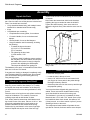
Assembling the Chimney Connector
SAFETY NOTE: Always wear gloves and safety
goggles when drilling, cutting or joining sections
of chimney connector.
• Beginning at
the flue collar
Toward
of the stove,
Stove
assemble the
chimney
connector.
Insert the first
crimped end
into the stove’s
flue collar, and
keep each
Flue Gas
crimped end
Direction
pointing toward
the stove.
Using the
ST242
holes in the
Fig. 5 Crimped sections always point
flue collar as
toward the stove so that any liquid
guides, drill
condensation will not leak out.
1/8” (3mm)
holes in the bottom of the first section of chimney
connector and secure it to the flue collar with three
#10 x 1/2” sheet metal screws.
• Secure each joint between sections of chimney
connector, including telescoping joints, with at least
three sheet metal screws. The predrilled holes in the
top of each section of chimney connector serve as
guides when you drill 1/8” (3mm) holes in the bottom
of the next section.
• Secure the chimney connector to the chimney.
Securing the Connector
to a Prefabricated Chimney
Follow the installation instructions of the chimney
manufacturer exactly as you install the chimney. The
manufacturer of the chimney will supply the accessories to support the chimney, either from the roof of the
house, at the ceiling of the room where the stove is
installed, or from an exterior wall.
Special adapters are available from your local dealer to
make the connection between the prefabricated chimney and the chimney connector. The top of such
adapters attach directly to the chimney or to the
chimney's ceiling support package, while the bottom of
the adapter is screwed to the chimney connector.
These adapters are designed so the top end will fit
outside the inner wall of the chimney, and the bottom
end will fit inside the first section of chimney connector.
Any soot or creosote falling from the inner walls of the
chimney will stay inside the chimney connector.
Securing the Connector
to a Masonry Chimney
The Sequoia may be connected to either a freestanding masonry chimney or a masonry fireplace chimney.
Freestanding Installations
If the chimney connector must pass through a combustible wall to reach the chimney, follow the recommendations in the wall pass-through section that follows.
The opening through the chimney wall to the flue (the
“breech”) must be lined with either a ceramic or metal
cylinder, called the “thimble”, which is securely cemented in place. (Fig. 5) Most chimney breeches
incorporate thimbles, but check to be sure the fit is
snug and the joint between thimble and chimney wall
firmly cemented.
Chimney
Flue Liner
Flue
Elbow
Instructions for various installations follow.
Thimble
• Be sure the installed stove and chimney connector
are correct distances from nearby combustible
material.
NOTE: Special slip pipes and thimble sleeves that form
telescoping joints between sections of chimney connector are available to simplify installations. They can
eliminate the need to cut individual connector sections.
Consult your local dealer about these special pieces.
Slip Pipe
Chimney
Connecotor Pipe
Flue Collar
Floor Protector
ST747
Fig. 6 Installing the chimney connector to a lined masonry
chimney.
6
2001049
Dutchwest Sequoia
A special piece called the "thimble sleeve," slightly
smaller in diameter than the standard connector and
most thimbles, will ease the removal of the chimney
connector system for inspection and cleaning. (Fig. 6)
Thimble sleeves should be available from your local
dealer.
24"
(610mm)
Chimney
Connector Shield
Block-Off Plate
Thimble
Sleeve
Flue
Elbow
Chimney Connector
Thimble
Keep
Sleeve
End Flush
with Flue
Tile
Chimney
Connector
ST244b
Flue Liner
ST243
Fig. 7 The thimble, made of either ceramic or metal, must be
cemented in place securely.
To install a thimble sleeve, slide it into the breech until it
is flush with the inner flue wall. Do not extend it into the
actual flue passage, as that could interfere with the
draft.
The thimble sleeve should protrude 1-2" (25-50 mm)
into the room. Use furnace cement and thin gasketing
to seal the sleeve in place in the thimble. Secure the
chimney connector to the outer end of the sleeve with
sheet metal screws.
Fireplace Installations Above the Fireplace
In this installation, the chimney connector rises from
the stove, turns ninety degrees, and goes back into the
fireplace chimney. The liner of the fireplace chimney
should extend at least to the point at which the chimney connector enters the chimney. Follow all the
guidelines for installing a chimney connector into a
freestanding masonry chimney, and pay special
attention to these additional points:
• Check the stove and chimney connector clearances
Fig. 8 The connector enters flue above the fireplace. If the
clearance between the chimney connector and either the
mantel and/or the ceiling is inadequate, special protective
shields will be required.
Fireplace Installations Through the Fireplace
If the height of your fireplace opening is at least 30”
(762mm), you may install a Sequoia through the
opening using a “positive connection” kit available from
your local dealer. These kits ensure a tight fit between
the stove flue collar and the chimney flue.
Fireplace installations, whether connected to the flue
above or through the fireplace opening, have special
clearance requirements to adjacent trim and the
mantel. You will find the required safe clearances for
Sequoia fireplace installation on Page 10.
Floor protection requirements also apply to fireplace
installation. Be sure to review the floor protection
requirements on Page 8.
Flue Liner
Extend Chimney
Connector to the First
Tile of the Flue Liner
to combustible mantel or trim materials. Use the
necessary combination of mantel, trim, and connector heat shields to provide the required clearances.
(Fig. 8)
Damper
Plate is
Remvoed
or Locked
in Open
Position
Observe
Miniumum Clearances
• Double-check connector clearance from the ceiling.
• The fireplace damper must be closed and sealed to
prevent room air from being drawn up the flue,
reducing the draft. However, it must be possible to
re-open the damper to inspect or clean the chimney.
Fireplace
Adapter Kit
ST245a
Close Off the
Damper
Opening with
Sheet Metal
and Sealant
Fig. 9 The connector passes through the fireplace to enter
flue. Special Fireplace Adapter Kits to simplify fireplace
installations are available from your local dealer.
2001049
7
Dutchwest Sequoia
Wall Pass-Throughs
Whenever possible, design your installation so the
connector does not pass through a combustible wall. If
you must use a wall pass-through in your installation,
check with your building inspector before you begin
and construct it in accordance with local building
codes. Also check with the chimney connector manufacturer for any specific requirements.
Accessories are available for use as wall passthroughs. If using one of these, make sure it has been
tested and listed for use as a wall pass-through.
In the United States, the national Fire Protection
Association (NFPA) has established guidelines for
passing chimney connectors through combustible walls.
Many building code inspectors follow these guidelines
when approving installations.
Figure 10 shows one NFPA-recommended method. All
combustible material in the wall is cut away a sufficient
distance from the single-wall connector to provide the
required 12” (305mm) clearance for the connector. Any
material used to close up the opening must be noncombustible.
In Canada, the Canadian Standards Association has
established different guidelines. Figure 11 shows one
method, in which all combustible material in the wall is
cut away to provide the required 18” (457mm) clearance for the connector. The resulting space must
remain empty. A flush-mounted sheet metal cover may
be used on one side only. If covers must be used on
both sides, each cover must be mounted on noncombustible spacers at least 1” (25mm) clear of the wall.
Your local dealer or your local building inspector can
provide details of other approved methods of passing a
chimney connector through a combustible wall. In
Canada, this type of installation must conform to CAN/
CSA-B365, Installation Code for Solid Fuel Burning
Appliances and Equipment.
NOTE: Do not vent your Sequoia into a factory-built
(zero-clearance) fireplace. These appliances and their
chimneys are specifically designed as a unit for use as
fireplaces. It may void the listing or be hazardous to
adapt them to any other use.
DO NOT CONNECT THE HEATER TO ANY AIR
DISTRIBUTION DUCT OR SYSTEM.
18” (450mm)
Empty Space All
Around the
Chimney
Connector
Chimney
Connector
Sheet Metal
Cover
(One side
only)
1/2” (13mm)
Noncombustible
Material
ST728
ST727
Fig. 10 Wall pass-through enclosed with noncombustible
materials.
Three other methods are also approved by the NFPA.
These are:
• Using a section of double-wall chimney with a 9”
•
•
8
clearance to combustibles.
Placing a chimney connector pipe inside a ventilated
thimble, which is then separated from combustibles
by 6” of fiberglass insulating material.
Placing a chimney connector pipe inside a section of
8” diameter, solid-insulated, factory-built chimney,
with 2” of air space between the chimney section
and combustibles.
Fig. 11 Hollow wall pass-through.
Floor Protection
A tremendous amount of heat radiates from the bottom
plate of your Sequoia stove. The floor area directly
under and around the stove will require protection from
radiant heat as well as from stray sparks or embers
that may escape the firebox.
Heat protection is provided through the use of a
Dutchwest Bottom Heat Shield. Spark and ember
protection must be provided by a floor protector
constructed with noncombustible material as specified.
Most installations will require that the bottom heat
shield be attached. Only when the stove is placed on a
2001049
Dutchwest Sequoia
completely noncombustible surface such as unpainted
concrete over earth may be used without the heat
shield.
Even when the bottom heat shield is installed, you
must provide special protection to the floor beneath.
For installation with the heat shield attached, use a
noncombustible floor protector such as 1/4" nonasbestos mineral board or equivalent, or 24 gauge
sheet metal. The floor protector may be covered with a
decorative noncombustible material if desired. Do not
obstruct the space under the heater.
Protection requirements vary somewhat between the
United States and Canada as follows:
U.S. Installations: The floor protector is required
under the stove and must extend at least 16” from the
front and left (loading door) side of the stove, and at
least 6” from the right side and rear. (Fig. 12) It must
also extend under the chimney connector and 2” to
either side. Refer to Figure 12 for minimum noncombustible floor protection dimensions.
To meet these requirements, a floor protector must be
at least 48” wide and 42” deep.
In Canada: a noncombustible floor protector is required under the heater also. The floor protector must
extend 18” (457mm) from the front and left (loading
door) side of the stove, and at least 6” (150mm) from
the right side and rear. (Fig. 12) It must also extend
under the chimney connector and 2” to either side.
Refer to Figure 12 for minimum noncombustible floor
protection dimensions.
In addition, a pad measuring 18” (457mm) wide by 24”
(610mm) long consisting of 1/2” (13mm) thick rigid
insulation board with a K value of .23 or less (such as
Carborundum Duraboard LD or Manville Ceraform
126) is also required; it must be centered and must
extend 16” (406mm) in front of and 8” (203mm) under
the unit. The floor protector may be covered with a
noncombustible decorative material if desired. Do not
obstruct the space under the heater.
C
C
E
B
E
D
D
E
D
D
A
A
A.
B.
C.
D.
E.
U.S.
48”
42”
2”
16”
6”
Canada
50” (1270mm)
44” (1118mm)
2”
(51mm)
18” (457mm)
6”
(152mm)
ST729
Fig. 12 Required floor protection dimensions.
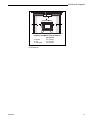
Floor Protection for Fireplace
Do not assume that your fireplace hearth is completely
noncombustible. Many fireplace hearths do not satisfy
the “completely noncombustible” requirement because
the brick or concrete in front of the fireplace opening is
supported by heavy wood framing. Because heat
passes readily through brick or concrete, it can easily
pass through to the wood. As a result, such fireplace
hearths can be a fire hazard and are considered a
combustible floor. (Fig. 13)
To meet these requirements, a floor protector must be
50” (1270mm) wide and 44” (1118mm) deep.
Due to the side loading door, floor protector requirements call for more protection on the left side than on
the right. If you wish a more balanced look, increase
the other side of the hearth as well. Do not reduce
side protection under any circumstances.
NOTE: In both the United States and Canada, no
bottom heat shield is required when the optional
pedestal base is used in place of the standard legs.
2001049
Wood Framing
ST730
Fig. 13 Combustible supporting timbers may lie beneath
fireplace hearths; such situations require additional floor
protection.
For all fireplace installations, follow the floor protection
guidelines described above. Keep in mind that many
raised hearths will extend less than the required
clearance from the front of the heater. In such cases,
sufficient floor protection as described above must be
added in front of the hearth to satisfy the minimum
floor protector requirement from the front of the stove:
16” (406mm) in the United States and 18” (457mm) in
Canada.
9
Dutchwest Sequoia
Hearth rugs do not satisfy the requirement for floor
protection as they are not fire proof.
Fireplace installations also have special clearance
requirements to the side walls, side decorative trim and
fireplace mantel. Refer to the information on fireplace
and mantel trim shields in this section.
Keep the Stove a Safe Distance from
Surrounding Materials
Both a stove and its chimney connector radiate heat in
all directions when operating. A safe installation
requires that adequate clearance be maintained
between the stove and nearby combustible materials to
ensure that such materials do not overheat.
Clearance is the distance between either your stove or
chimney connector, and nearby walls, floors, the
ceiling, and any other fixed combustible surface. Keep
furnishings and other combustible materials away from
the stove as well. In general, a distance of 48" (1220
mm) must be maintained between the stove and
moveable combustible items such as drying clothes,
furniture, newspapers, firewood, etc. Keeping those
clearance areas empty assures that nearby surfaces
and objects will not overheat.
insulation board such as Durock® or Wonderboard®, or
common brick “laid on flat,” with the 3¹⁄₂" (90 mm) side
down.
Shields must be spaced out from the combustible
surface 1" (25 mm) on noncombustible spacers, as in
Figure 14. The spacers should not be directly behind
the stove or chimney connector.
Air must be able to flow between the wall and the
shield. At least 50% of the bottom 1" (25 mm) of the
shield must be open, and the shield must be open at
the top. (Fig. 14)
Air Flow
Wall Shield
Stud Wall Framing
Noncombustible Spacers
and Fasteners
Drywall
Safe Ways to Reduce Clearances
Your stove has specific clearance requirements that
have been established through careful research and
testing to UL and ULC standards.
Clearance requirements have been established to meet
every installation possibility, and they involve the
combination of basic variables:
•
•
•
•
When the stove has no listed heat shield
When the stove has a listed heat shield
When the wall has no heat shield
When the wall has a heat shield
In general, the greatest clearance is required when you
locate a stove with no heat shield near a wall with no
heat shield. The least clearance is required when both
the stove and the wall have heat shields. Reducing a
stove clearance may require a listed heat shield on the
chimney connector as well, or a double-wall connector.
Clearances may be reduced only by means approved
by the regulatory authority and in accordance with the
clearances listed in this manual. The charts and sample
installations that follow list all the clearances required
for the various installation configurations of Sequoia.
Air Flow
ST248
Fig. 14 Approved wall shield construction.
Fireplace Installations
A fireplace installation requires special clearance
between the side of the stove and the right and left
walls, between the side of the stove and the decorative
side trim on the fireplace face, and between the top of
the stove and the mantel.
Ventilated, noncombustible shields installed on
noncombustible spacers 1” (25mm) away from the
combustible surface may be used to reduce
clearances. A mantel shield for the Sequoia must be at
least 48” (1220mm) long, centered over the stove. Side
trim shields must extend the full length of the trim.
In addition, a fireplace installation must observe the
floor protection guidelines discussed previously.
The charts and illustrations that follow depict all the
clearances required for the various installation
configurations of the Sequoia.
Wall Shields
One way to reduce clearances is with a wall shield
constructed of 24 gauge or heavier sheet metal, or of
another noncombustible material such as 1/2" (13 mm)
10
2001049
Dutchwest Sequoia
A
B
C
C
B
B
ST731
Fireplace and Mantel Trim Clearances
A. Mantel
B. Trim
C. Side Walls
Unprotected
24” (610mm)
24” (610mm)
32” (813mm)
Fig. 15 Maintain clearances to combustible components of
the mantelpiece.
2001049
11
Dutchwest Sequoia
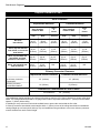
Sequoia Clearance Chart
Stove Clearance
Unprotected Surfaces
Protected Surfaces
Stove Installed
Parallel to Wall
Stove
in
Corner
Side
Rear
Corners
Side
Rear
No stove
heat shields1
(A) 32”
(813mm)
(B) 42”
(1067mm)
(C) 36”
(914mm)
(D) 16”
(406mm)
(E) 26”
(660mm)
(F) 20”
(508mm)
Stove, top exit with rear
heat shield, no connector
heat shields
(G) 32”
(813mm)
(H) 42”
(1067mm)
(I) 36”
(914mm)
(J) 16”
(406mm)
(K) 26”
(660mm)
(L) 20”
(508mm)
Stove, top exit with rear
heat shield, and heat
shields on connector1,2,3
(M) 32”
(813mm)
(N) 20”
(508mm)
(O) 26”
(660mm)
(P) 16”
(406mm)
(Q) 14”
(356mm)
(R) 12”
(305mm)
Stove, rear exit with rear
heat shield only
(S) 32”
(813mm)
(T) 20”
(508mm)
N/A
(U) 16”
(406mm)
(V) 14”
(356mm)
N/A
Stove Installed
Parallel to Wall
Stove
in
Corner
Corners
Chimney Connector Clearance
Unprotected Vertical Surfaces
No chimney connector
heat shields
Chimney connector
heat shields installed2
Protected Vertical Surfaces
36” (914mm)
19” (483mm)
14” (356mm)
8” (203mm)
Clearance to Combustibles in Front of Stove
All Installations
48” (1219mm)
1 All installations venting straight up to a factory-built chimney require a 24” (610mm) diameter or square ceiling heat
shield. The ceiling heat shield should be 24 gauge sheet metal or equivalent mounted on 1” (25mm) noncombustible
spacers 1” (25mm) below ceiling.
2 Shielding for a top exit stove must include a shield insert to protect the area behind the flue collar.
3 Chimney connector heat shields must extend to within 1” (25mm) or less of the ceiling heat shield for installations
venting straight up to a factory-built chimney. Top exit installations using an elbow to vent to rear chimney connector
must be shielded over entire vertical length.
12
2001049
Dutchwest Sequoia
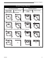
Sequoia Clearance Diagrams
Unprotected Surfaces
Stove Installed
Parallel to Wall
Protected Surfaces
Stove in Corner
Stove Installed Parallel
to Wall
Stove in Corner
Top Exit Installations, no heat shields
C
B
F
E
A
D
C
F
Top Exit Installations, rear heat shield, no connector heat shields.
I
H
L
K
G
J
I
L
Top Exit Installations, rear heat shield, heat shield on connector.
O
N
R
Q
M
P
O
R
Rear Exit Installations, rear heat shield only.
T
V
N/A
N/A
S
U
ST732
2001049
13
Dutchwest Sequoia
Wall Shield Requirements for Common Sequoia Installations
32"
(813mm)
32"
(810mm)
1"
(25mm)
1"
(25mm)
58"
(1473mm)
58"
(1473mm)
14"
(356mm)
14"
(356mm)
36"
(914mm)
36"
(914mm)
1"
(25mm)
17"
(432mm)
1"
(25mm)
48"
(1219mm)
60"
(1524mm)
ST750
ST749
32"
(813mm)
1"
(25mm)
1"
(25mm)
32"
(813mm)
1"
(25mm)
58"
(1473mm)
12"
(305mm)
19"
)
(4 8 3 m m
36" *
(914mm)
1"
(25mm)
55" )
9mm
(139
32"
(813mm)
1"
(25mm)
58"
(1473mm)
58" **
(1473mm)
4"
(104mm)
27"
)
(6 8 6 m m
63" )
mm
0
(160
)
36"
(914mm)
1"
(25mm)
ST751
* When optional pedestal is used instead of standard legs, the
wall shield height is 39¹⁄₂” (1003mm).
14
1"
(25mm)
58"
(1473mm)
19"
(483m
m)
55
(149 "
9mm
32"
(813mm)
36" *
(914mm)
1"
(25mm)
63
(160 "
0mm
)
36"
(914mm)
1"
(25mm)
ST751
** Or within 1” of ceiling.
2001049
Dutchwest Sequoia
Distance from the Center of the Flue Collar to the Wall in Top Exit Sequoia Installations
The information on this page is helpful in planning stove placement for top exiting installations, particularly those
installations with chimneys that pass through the ceiling. However, this is not a clearance chart. For clearance information, refer to the clearance chart on Page 12. The terms “Side” and “Rear” refer to the distance from the center of
the flue collar to the respective wall. The term “Front” refers to the distance from the center of the flue collar to the
front edge of the hearth. The asterisk indicates U.S./Canada.
Sequoia WITHOUT Stove and Chimney Connector Heat Shields
Unprotected Surfaces
Stove Installed
Parallel to Wall
Side
Rear
Front
(A)
(B)
(C)
45”
20”
37” / 39”*
1143mm 508mm 940/991mm
B
Protected Surfaces
Stove
inCorner
Corners
Front
(D)
(E)
44”
37” / 39” *
1118mm 940/991mm
A
Stove Installed
Parallel to Wall
Side
Rear
Front
(F)
(G)
(H)
29”
23”
37” / 39”*
737mm 584mm 940/991mm*
D
Stove
in Corner
Corners
Front
(I)
(J)
28”
37” / 39”*
711mm 940/991mm*
F
G
I
D
I
C
H
E
J
Sequoia WITH Stove and Chimney Connector Heat Shields
Unprotected Surfaces
Stove Installed
Parallel to Wall
Side
Rear
Front
(K)
(L)
(M)
45”
18”
37” / 39”*
1143mm 457mm 940/991mm
L
K
Protected Surfaces
Stove
inCorner
Stove Installed
Parallel to Wall
Corners
Front
(N)
(O)
34”
37” / 39”*
864mm 940/991mm
N
Side
(P)
29”
737mm
Q
Rear
Front
(Q)
(R)
12”
37” / 39”*
305mm 940/991mm*
P
Stove
in Corner
Corners
Front
(S)
(T)
20”
37” / 39”*
508mm 940/991mm*
S
N
M
2001049
O
S
R
T
15
Dutchwest Sequoia
Assembly
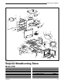
Unpack the Parts
Remove all loose parts from the firebox and the ash
pan. Check to make sure all the parts are included and
intact. You should have received:
• 1 fully assembled heater body, (with catalytic burner
installed in its chamber below the stove top)
*Bottom heat shields are standard only on stoves sold
in Canada.
Next, fasten the bottom heat shield to the brackets,
adjusting the legs as needed to make the shield fit.
Tighten the shield securely, then use a wrench to
tighten the leg bolts firmly. Now raise the stove onto its
legs.
• 4 legs
• 1 Installed ash pan containing:
• 1 Replacement Interam gasket, for combustor
• 1 Ceramic Handle, for use on the doors and
Leg Bolt
Threaded
Hole
damper
Bottom Heat
Shield
Bracket
• 1 Brass Handle, for use on dial dampers
• 1 bag of hardware used for assembly, including
the following:
• To attach the legs to the stove:
(4) 1/4-20 x 1” hex head bolts
(4) 1/4” washers
• For tightening the door latch:
(1) Allen wrench, 5/32”
• also...
(1) Spring, which fit inside the square socket in
the iron part of the door handles, and will push
the handle off the stove in case you forget to
remove it after adjusting the dial dampers.
This keeps the handles from getting hot.
The hardware in the stove is in standard US sizes. Most
bolts are 1/4-20 and 7/16 heads.
If any parts are missing or damaged, immediately notify
your Dutchwest dealer for replacements. Do not install
your stove without having all necessary parts or by
using damaged parts.
Attach the Legs and Heat Shield*
Since you have already received delivery of your
Sequoia, you are aware of how heavy it is. To safely
accomplish the setup and installation of the Sequoia,
you should have two or more strong assistants to help
move it.
Place the stove on its back on a soft surface such as a
couple of old blankets. Tilt it carefully. Protect surrounding carpet with an old blanket or sheet.
First, loosely install a bottom heat shield bracket and
leg to each corner of the stove. Place a 1/4-20 x 1” bolt
through the unthreaded hole in the bracket so the
bracket’s threaded hole will extend below the leg.
Position the leg, and fasten it to the stove finger-tight
with bolt. Repeat this step for each of the four legs.
16
Leg
ST753
Fig. 16 Attach bottom heat shield brackets and legs to stove
using 1” bolts.
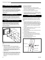
Install the Fittings
To install the catalytic probe:
• Locate the hole in the top of stove.
• Insert a 1/4” drill bit in the hole and rotate it with
your fingers to clear a path for the probe through
the fragile refractory material.
• Insert the probe stem into the stove top and through
the prepared opening.
Your stove has been shipped with grate covers installed. These must remain installed when burning
wood, but should be removed for burning coal.
The hardware in your stove is in standard US sizes.
Most bolts are 1/4”-20, with 7/16” heads. Some of the
hex-head bolts have metric heads. Use wither a 3/8”
(10mm) wrench, or an 8mm wrench or pliers if you are
attaching a blower to the stove.
The multipurpose brass handle will operate the two
spin-dial air controls, the doors and the stove damper.
2001049
Dutchwest Sequoia
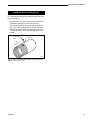
Install Air Duct for Outside Air
If your installation will include outside air for combustion, follow these directions for attaching the three inch
duct to the stove:
• Screw a #10 x 1/2” sheet metal screw into the duct.
Tighten the screw, then back it off two turns.
• The outside air port on the back of the stove has a
slot at the 10:00 o’clock position. Align the screw in
the duct pipe with the slot and insert the pipe. Turn
1/4 turn, clockwise. This locks the pipe securely in
position.
#10 x 1/2”
Sheet Metal
Screw
1/8” Hole
3/4”
ST754
Fig. 17 Drill a 1/8” hole in the crimped end of the three inch
pipe duct, 3/4” from the end.
2001049
17
Dutchwest Sequoia
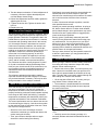
Operation
The Sequoia Controls
Air Controls
The Sequoia has three air controls that regulate the
amount of air drawn into the stove. Generally, more air
entering the stove makes the fire burn hotter and
faster, while less air prolongs the burn.
The Primary Air Control is the lever located on the
upper right side of the stove front and is the primary
source of air for starting and maintaining wood fires. It
is always closed when burning coal. It opens when
moved clockwise and closes when moved counterclockwise.
Primary
Air
Control
Lever
(Not
visible)
Damper
Combustor
Air
Control
Front
Loading
Door
The stove damper must be open when starting a fire,
when reloading fuel (for a short time only), and when
the side or front doors of the stove are opened for any
reason. It may also be left open when burning coal
whenever maximum heat is needed.
Load Doors
The Side Loading Door allows the easiest loading of
wood logs.
When the Sequoia is equipped with an 8” (200mm) flue
collar, the Front Door may be utilized as well for
loading coal or for adding an occasional log to wood
fires. Also, the front door may be opened wide and an
optional spark screen, Part No. 0135, placed in the
opening for safe, fireplace-style viewing when burning
wood. The front door must remain closed at all times
when the 6” (150mm) flue collar is used.
With either flue size, the fire may still be viewed
through the large ceramic viewing window when the
front door is closed.
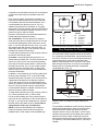
A Probe Thermometer Port Provides
Access to Internal Temperatures
Side
Loading
Door
Coal-Only Air
Control
ST740
Fig. 18 All stove controls are conveniently accessible and
easy to regulate.
Insert the Probe Thermometer into the access port
(see directions on Page 16) as a valuable guide that
will tell you when to open and close the stove damper,
when to increase or decrease the air supply, whether
or not the stove’s catalytic combustor is working
properly when you are burning wood, and when to add
fuel.
Port for Probe
Thermometer
The Combustor Air Control is located on the left side
of the stove, above the side loading door, and delivers
preheated air to a strategic internal site to aid catalytic
combustion when burning wood. This control is closed
completely when burning coal. Turn counterclockwise
to open and clockwise to close.
The Coal-only Air Control is positioned on the access
door to the ash drawer compartment. It is the air supply
for starting and maintaining coal fires. This control
must be closed completely when burning wood. As
with the combustor air control, turn counterclockwise to
open and clockwise to close.
Damper Function
ST741
Fig. 19 The probe thermometer is a valuable guide to stove
operation.
The Damper is operated by moving the small, square
knob on the left side of the stove. It has two positions:
open, to start or revive the fire; and closed for greatest
efficiency and heat. Using the multipurpose door
handle, rotate the damper knob counterclockwise to
open the damper and clockwise to close it.
18
2001049
Dutchwest Sequoia
Successful Wood Burning
Burning wood and coal is often said to be more of an
art than a science. You will easily master the art if you
start by using good, dry fuel and by understanding how
the stove’s air supply system operates.
Burn Only High-Quality Fuel
This heater is designed to burn natural wood only (or
coal, when the catalytic combustor has been removed
and the optional coal kit installed). Do not burn fuels
other than those for which this heater was designed.
Never burn pressure-treated wood, painted or stained
wood, or glossy newsprint.
High efficiencies and low emissions are possible when
burning air-dried, seasoned woods as compared to
softwoods or freshly cut hardwoods. Avoid burning
“green” wood that has not been properly seasoned.
The best hardwood fuels include oak, maple, beech,
ash, and hickory that has been split, stacked, and airdried outside under cover for at least one year. If
hardwood is not available, tamarack, yellow pine, white
pine, Eastern red cedar, fir, and redwood are softwoods
that are commonly burned. They too should be properly dried. The length of the wood should be the same
as that specified for your particular stove. Avoid using
wood that has been dried more than two years. Often
gray in color, this wood burns very quickly, resulting in
short burn time and diminished stove performance. If
you must burn it, mix it in with greener wood to slow the
burn. The length of the wood should be 23” (580mm).
When burning coal with the combustor removed, we
recommend that you use only premium grade anthracite. Three sizes of coal are commonly burned: pea
coal, a very small size averaging 3/8” to 3/4” (1020mm); nut coal, a medium size of 3/4” to 1¹⁄₂” (2040mm); and stove coal, the largest size at 1¹⁄₂” to 2³⁄₄”
(40-70mm).
NOTE: Coal may be burned in the Sequoia only when
the 8” (200mm) flue collar is used, and then only with
optional coal kit #5531 installed.
Both wood and coal should be stored under cover to
maintain dryness. Even for short-term storage, keep
wood and coal a safe distance from the heater and
keep it out of the areas around heater used for refueling
and ash removal.
Use the Air Control Settings
that Work Best for You
No single combination of control settings will fit every
situation. Each installation will differ depending on the
quality of the fuel, the amount of heat desired, and how
long you wish the fire to burn.
2001049
Control settings also depend on your particular
installation’s “draft," or the force that moves air from the
stove up through the chimney. Draft is affected by such
things as the height, type, and location of the chimney,
local geography, nearby obstructions, and other factors.
Too much draft may cause excessive temperatures in
the stove. On the other hand, too little draft can cause
backpuffing into the room and/or the “plugging” of the
chimney and catalytic burner.
How do you know if your draft is excessively high or
low? Symptoms of too much draft include an uncontrollable burn or a glowing-red part of the stove or chimney
connector. A sign of inadequate draft is smoke leaking
into the room through the stove or chimney connector
joints.
In some newer homes that are well-insulated and
weather-tight, poor draft may result from insufficient air
in the house. In such instances, an open window near
the stove on the windward side of the house will
provide the fresh air needed.
Another option for getting more combustion air to the
stove is to duct air directly from the outside to the stove.
In fact, in some areas provisions for outside combustion
air are required in all new construction.
Your Sequoia is designed to incorporate outside
combustion air, and directions for installing an outside
air duct may be found in the Assembly section.
When first using the stove, keep a record of the results
you achieve from different control settings. You will find
that specific control settings will give you a fixed
amount of heat. It may take a week or two to determine
the amount of heat and the length of burn you should
expect from various control settings.
Most installations do not require a large amount of
combustion air, especially if adequate draft is available.
Do not for any reason attempt to increase the firing
of your heater by altering the air control adjustment
range outlined in these directions.
Use the following air control settings as a starting point
to help determine the best settings for your installation:
NOTE: To make the settings for these directions as
clear as possible, imagine that the face of a clock is
mounted behind the primary air control lever. Then,
follow the directions to set the lever at the correct
“time”. (Fig. 20)
Sequoia Control Settings for Wood Fires
Burn Rate
Low
Medium
High
Primary Air
6:00
7:00
8:00 or greater
Combustor Air
1/2 turns
Fully Open
Fully open
(The coal-only control always remains closed, or
rotated fully clockwise.)
19
Dutchwest Sequoia
11 12
How to Build a Wood Fire
and Keep it Going
1
10
2
9
Make sure your stove is set up correctly for burning
wood.
3
8
4
7
6
A Sequoia leaves the factory with the catalytic
combustor installed.
5
In the United States it is against the law to operate this
wood heater in a manner inconsistent with the operating instructions in this manual, or if the catalytic combustor is deactivated or removed.
The grate covers are also installed. These are necessary for wood burning and should be left in place.
ST756
Fig. 20 The Sequoia’s primary air supply is closed at the 5
o’clock position, and fully open at 8 o’clock or more.
Sequoia Control Settings for Coal Fires
(The primary air and combustor air controls always
remain closed. Primary air is closed a the 5:00 position,
while the combustor air is closed when rotated fully
clockwise.)
Burn Rate
Coal-Only Air
Low
Medium
High
1/2 turn
1¹⁄₂ turns
Fully open
High-Efficiency Wood Burning
with Catalytic Combustion
Smoke from a wood fire is really escaping energy that
has not been burned to produce the heat. Combustion
temperatures of 1100°F (595°C) are required to burn
the smoke, and a level this high seldom is present in a
fire set to burn several hours. As a result, long fires in
conventional stoves lose a great deal of potential heat
up the chimney as smoke.
A catalytic combustor captures this heat by lowering the
temperature at which smoke will burn. This makes high
efficiency possible even with long, low level fires.
If your stove is equipped with an optional blower, it is
important to follow these guidelines as well for best
results:
At low-to-medium heat outputs, (a control setting of
6:00 to 7:00) the optional convection blower switch
should be set on the “low” position, never on “high”.
At higher heat outputs, (8:00 or more) the blower can
be set on high if desired.
NOTE: The coal-only air control must always be
closed during a wood fire. Likewise, the primary
and combustor air controls must be close when
burning coal.
DO NOT OPERATE THE STOVE WITH THE ASH
DOOR OPEN. THIS CAN CAUSE EXTREME
OVERFIRING OF THE STOVE, WHICH IS DANGEROUS.
The stove’s paint and cement will emit a slight odor
during the first few fires. We suggest that you
provide extra ventilation near the stove by partially
opening a door or window when the odor is
present.
20
ST743
Fig. 21 High-efficiency performance when burning wood is a
result of catalytic combustor that is coated with precious
metals to cause smoke to burn at temperatures lower than
normal.
Catalytic combustion is activated with two adjustments:
by closing the stove damper, thereby exposing the
smoke to the combustor, and by opening the combustor
air control. The combustor needs extra air during
medium and high burns, and the Sequoia’s combustor
air control must be fully open to supply it. During low
burns, the combustor air control should be open only a
1/2 turn.
Closing the stove damper also reduces the draft, so to
avoid putting out the fire or deactivating the combustor,
close the damper only when a fire is well established.
When starting a fire, wait until the fire is well established and there is an ember bed of at least two inches
before closing the stove damper.
2001049
Dutchwest Sequoia
Never kindle a fire with colored paper or paper that has
colored ink or a glossy surface, and never burn treated
wood, garbage, solvents, or trash. All of these may
poison the catalyst and prevent it from operating
properly. Never burn cardboard or loose paper except
for kindling purposes. This can cause smoke to spill into
the room and effect the combustor operation. Coal
smoke can also poison the catalyst so that it will not
operate properly.
When burning wood, your Sequoia may be operated
with the front doors open, for fireplace-style viewing, as
well as closed. The stove damper must be open and
the firescreen must be in place whenever the door is
open for fire viewing.
In general, the temperature in the stove and the gases
entering the combustor must be raised to approximately
800°F (430°C) to ensure that catalytic activity is initiated. During the start-up of a cold stove, a medium-to
high-firing rate must be maintained for about twenty
minutes. This ensures that the stove, catalyst and fuel
are all stabilized at the proper operating temperatures.
Your stove may be operated as a fireplace with the
doors opened or removed only when equipped with
an 8” (200mm) flue collar and only with the optional
spark screen placed correctly in the opening to
protect against the possibility of sparks and embers leaving the stove. The test standard for your
stove when it is operated in this mode is UL737.
Even though it is possible to have gas temperatures
reach several hundred degrees within two to three
minutes after a fire is started, the combustor may stop
working or the fire may go out if the fire is allowed to die
down immediately. Once the combustor starts working,
heat generated by burning the smoke will keep it
working.
Use only the Sequoia spark screen, Part Number
0135, with your Sequoia. Sequoia spark screens are
available from your Dutchwest authorized dealer.
The best operating range for the combustor is a reading
of 1000-1400°F (540-760°C) on a probe thermometer.
Temperatures over 1700°F (925°C) may damage the
combustor.
2. Place crumpled newspaper in the stove. Do NOT
use glossy advertisements or colored paper, as they
can poison the catalyst. Place six or eight pieces of
dry kindling split to a finger-width size on the paper,
and on the kindling lay two or three larger sticks of
split dry wood approximately 1-2” (25-50mm).
To determine whether the combustor is operating,
check the probe thermometer in the top of the stove. If
it reads 800° (430°C) or higher, it is likely that the
combustor is operating. If temperatures are lower than
this, increase the intensity of the fire either by adding
fuel or by increasing the amount of primary air.
Another way to tell if the combustor is working is to
observe the amount of smoke leaving the chimney
when the damper is activated and when it is not. This
procedure is described on Page 25.
Conditioning Your Stove
Cast iron is extremely strong, but it can be broken with
a sharp blow from a hammer or from the thermal shock
of rapid and extreme temperature changes.
The cast plates expand and contract with changes in
temperature. When you first begin using your Sequoia,
minimize thermal stress by allowing the plates to adjust
gradually during three or four initial break-in fires
following Steps 1-3 below.
Starting and Maintaining a Wood Fire
Wood may be loaded into the Sequoia from either the
front or the side. Loading from the front is useful for
kindling a new fire or adding an occasional log, but we
recommend side loading as the most convenient way of
regularly adding several logs at a time.
2001049
WARNING: For safety and greatest efficiency,
operate your stove only with all doors fully closed.
The test standard when the stove is operated in this
mode is UL1482.
1. Open the stove damper, and open the primary air
control fully. Open the combustor air control two
turns. The coal only air control must always be
closed during wood burning.
DO NOT USE CHEMICALS OR FLUIDS TO START
THE FIRE. DO NOT BURN GARBAGE OR FLAMMABLE FLUIDS SUCH AS GASOLINE, NAPTHA OR
ENGINE OIL. Also, never use gasoline-type lantern
fuel, kerosene, charcoal lighter fluid, or similar liquids to
start or “freshen up” a fire in this heater. Keep all such
liquids well away from the heater while it is in use.
3. Light the newspaper and close the door. Within 1015 minutes the fire should be well established and
you may gradually build up the fire by adding a few
3-5” (80-120mm) diameter splits. If this is one of the
first few “break-in” fires, let the fire burn brightly, and
then let it die out.
If the break-in procedure has been completed,
continue building the fire until you have a live ember
bed about 2” (50mm) thick.
You will soon find out that this stove is HOT WHILE IN
OPERATION! KEEP CHILDREN, CLOTHING AND
FURNITURE AWAY. CONTACT MAY CAUSE SKIN
BURNS.
NOTE: Some chimneys, especially oversized or
exterior chimneys, need to “primed”, or warmed up,
before they will draw sufficiently to start a fire. To
21
Dutchwest Sequoia
correct this situation, roll up a couple pieces of newspaper, place them on top of the kindling and toward the
back of the stove, light them and close the doors. This
should heat the chimney enough to initiate a draft.
Once the draft is established, open the front door and
light the rest of the fuel from the bottom. Do not light the
main bed of fuel until the chimney begins drawing, and
repeat the procedure as often as necessary if the initial
attempt is unsuccessful.
4. After the temperature on the probe thermometer has
reached 450-500°F (232-260°C) (depending on your
individual wood and draft situation), close the stove
damper. This will activate the combustor. To ensure
continued operation of the combustor, let the temperature approach at least 850°F (454°C) before
reducing the air settings.
5. Close the primary air control to a medium setting, or
about 6:00-7:00 on the imaginary clock face referred
to on Page 18. The fire volume will diminish immediately, but the stove will continue to warm up. Maintain control of the fire using the primary air and
combustor air controls, and remember: reduce the
setting for a smaller fire, increase the setting for a
larger fire. Refer back to the air control settings chart
on Page 18 for recommended settings at different
burn rates.
operation in response to these variables may be
helpful. To maintain good draft under adverse conditions, refuel as often as necessary to keep the bed of
the firebox covered with a ‘robust’ layer of hot coals.
Run the stove at temperatures a little above minimum
recommended temperatures.
Remove and Store Ash Safely
Wearing protective stove gloves, check the ash pan
before reloading the stove. If the ash level is close to
the top, empty the pan. Before replacing the ash pan,
clear away any ash that has spilled over the sides and
back of the pan.
When burning wood, empty the ash drawer regularly,
typically every one to three days. The frequency will
vary depending on how hot you run your stove: the
hotter the fire, the more wood you burn, and the faster
ash will accumulate.
Ash may contain hot coals and must be treated with
extreme care.
Coal ash will accumulate rather quickly and will require
emptying the ash drawer at least once a day. Empty it
before shaking and reloading to allow the newly-shaken
ash to cool before the next shakedown.
DO NOT OVERFIRE THIS HEATER. Overfiring may
cause a house fire, or can result in permanent damage
to the stove and to the catalytic combustor. If an
exterior part of the stove or the chimney connector
glows, you are overfiring.
Reloading and Reviving a Wood Fire
Open the stove damper and wait at least fifteen seconds for the draft to increase. Open the door slowly and
add the fuel. Split wood will fill the firebox more completely and reduce the frequency of reloading.
Leave the stove damper open for a short time until the
probe temperature reaches 800°F (430°C), then close
it.
Frequently the temperature will drop below 800°F
(430°C) after reloading, particularly if the loading door is
open a long time. Should the temperature drop below
this level, stimulate the fire by increasing the primary air
supply while leaving the stove damper open. Reduce
the air supply and close the stove damper when the
temperature has reached 800°F (430°C).
NOTE: If the charcoal bed is relatively thick and your
fuel is well-seasoned, it is possible to add fresh fuel
(smaller pieces first), close the door and damper, and
reset the air control within five minutes.
Draft is affected by a number of variables, such as
outside temperatures and quality of fuel. Adjusting your
22
ST744
Fig. 22 Wear a heavy stove glove for protection when
removing ash.
Always Dispose of Ash in a Safe Manner
Ash should be removed frequently and placed outdoors
in a metal container with a tight-fitting lid. The closed
container of ash should be placed on a noncombustible
floor or on the ground, well away from all combustible
materials, pending final disposal. If the ash is disposed
of by burial in soil or otherwise locally dispersed, it
should be retained in the closed container until all
cinders have thoroughly cooled. Wood ash may be
used as a garden fertilizer.
CAUTION: Never use a vacuum cleaner to remove ash
from the stove; always remove and dispose of the ash
properly.
2001049
Dutchwest Sequoia
Maintenance
Keep Your Stove Looking New And
Working Its Best
Care of the Cast Iron Surface
An occasional dusting with a dry rag will keep the
painted cast iron of your Sequoia looking new.
If the paint needs retouching, allow the stove to cool
completely. Wire-brush areas needing to be painted.
Remove non-painted components such as air controls
or cover them with masking tape. Touch up the stove
with high temperature stove paint available from your
local dealer. Apply the paint sparingly. Two light coats
are better than one heavy one.
cement or a smaller diameter gasket into the channel
beneath the gasket to lift the main gasket and thereby
improve its contact with the door frame.
If shimming does not improve the seal, replace the
gasket following these steps:
1. Remove the original gasket by grasping an end and
pulling firmly.
2. Wearing safety goggles, use a wire brush or the tip
of a screwdriver to clean the channel of any remaining cement or bits of gasket. (Fig. 23)
To remove stains or spills from porcelain enamel, first
make sure the stove is completely cool. Use a dry rag
or soft brush, and use only a kitchen appliance cleaner
or polish recommended for enamel surfaces.
Cleaning the Glass
Most of the carbon deposits on the glass will burn off
regularly during hot fires. If you wish to clean the glass
more thoroughly, follow this procedure:
•
•
•
Be sure the glass is completely cool.
Use a glass cleaner especially made for this
purpose.
Dry the glass completely.
ST560
Fig. 23 Remove gasket then clean channel with wire brush.
3. Apply a thin bead of stove cement in the newlycleaned groove. (Fig. 24)
4. Lay the gasket into the groove. Wait until you are a
couple inches from the end before you cut it.
Repair Air Leaks to Prevent Overheating
Self-Adjusting Door Latches
A tight seal of the doors ensures precision control over
the firing rate, and prevents inadvertent overfiring. The
self-adjusting design of your stove’s door latch enables
you to control the tightness of the seal each time you
close the door.
To achieve greater tightness, turn the handle more in a
clockwise direction. Each movement of the handle
draws the door closer to the stove.
Do not use excessive force when tightening the door
latch. A tight seal is made when only moderate pressure is applied to the handle.
Test and Repair the Door Gaskets
Air leaks can be caused by low spots in the door
gaskets. To locate such low spots, close each door on
a slip of paper and attempt to pull the paper free. If the
paper slips out without tearing, the gasket is not snug
enough at that spot.
If the seal cannot be improved by adjusting the door
latch, try shimming the gasket. Pack a small quantity of
2001049
et
ask
ve G ent
Sto Cem
ST561
Fig. 24 Lay a bead of gasket cement then press gasket in
place.
5. Test the gasket by closing the door on a slip of paper
as described above. Adjust the gasket in any areas
where an inadequate seal is evident. Allow the
cement to dry 24 hours before firing your stove.
All rope-type gasketing used in the Sequoia is made of
fiberglass. The gasket size for the front, side and ash
doors, as well as for the top and inner top, is 3/8”
diameter. The front door glass is sealed with a 3/16”
gasket, while the flue collar employs a 1/4” size. Two
small pieces of 1/4” wire gaskets are used inside the
Sequoia between the grate seals and the left side
plate, and a special Interam® gasket wraps around the
combustor to provide a seal.
23
Dutchwest Sequoia
Repair Missing Cement in Seams
The cement in the stove seams may deteriorate over
time and fall out in places. Just as with the stove
doors, it is necessary to keep the seam seals in good
condition. Spot-fix with furnace cement (available from
your local dealer) any areas where the cement seal is
visibly deteriorated. Allow 24 hours for the new
cement to dry.
Avoid Damaging the Glass
Do not abuse the glass by slamming the door or striking
the glass with a log. Never operate your stove if it has
damaged or broken glass. If you need to replace the
glass, use only replacement glass provided by your local
Sequoia dealer.
Replace Broken Glass Immediately
Prepare to replace the glass in your stove by first
clearing a large flat area nearby to use as a work
surface. Place in order the pieces that you disassemble. This will be a great help when you put the
pieces back together.
Door Frame
Brass Frame
Gasket
Glass
Glass
Retaining
Clip
ST745
3. Remove the old gasket.
To install the new glass:
1. Place a new piece of 3/16” gasket around the
perimeter of the brass frame for the glass to rest on,
as far to the outside as possible.
2. Place the new piece of glass on the gasket.
3. Position the glass retainer clips, and fasten in place
with the 7/16” bolts previously removed. Tighten the
bolts alternately. Do not over-tighten.
Damper Adjustment
Check the damper to confirm that it is locking tightly
whenever the top is removed for combustor inspection.
If the damper needs adjustment, use a 7/16” socket
wrench with a socket extension and follow this procedure:
1. Remove the stove top plate. It is held in place by
two bolts. these bolts are accessible when you open
the front door and look upward toward the underside of the top plate. Remove the two bolts. NOTE:
The left hand bolt is more accessible through the
side door.
2. Lift the top plate off the stove. It is heavy, you may
choose to have a helper assist you.
3. Open the damper.
4. If necessary for better access, carefully remove the
refractory cover.
5. Loosen the adjusting bolt’s lock nut.
6. Loosen the anchor bolt’s lock nut located on the
back side of the damper and accessible inside the
stove through the front door.
7. Loosen the anchor bolt a turn or two.
8. Tighten the adjusting bolt.
Bolts
Fig. 25 In order of assembly, the front door glass components include a brass frame, gasket, glass, two clips and four
bolts.
Adjusting Bolt
Front of
Stove
To remove the glass:
1. Open the front door. Lift the door gently while
raising the end nearest you slightly. This will cause
the bottom hinge pin to leave its seat. Once the
bottom hinge pin is free, lower the door to free the
top hinge pin. Place the door face down on a
padded surface.
2. Remove the 7/16” bolts holding the stainless steel
glass retaining clips on the left and right sides of the
glass. Remove the clips and lift the glass off the
brass frame. Lift broken glass carefully to avoid
being cut.
24
Lock Nut
Anchor Bolt
Damper Rod
ST441
Fig. 26 Damper adjustment.
2001049
Dutchwest Sequoia
9. Test the damper mechanism. If further adjustment is
necessary, continue to tighten the adjusting bolt
until the damper closes snugly.
10. When final adjustment has been made, tighten the
adjusting bolt lock nut.
11. Tighten the anchor bolt. Tighten the anchor bolt
lock nut.
12. Replace the top.
Care of the Catalytic Combustor
This wood heater contains a catalytic combustor, which
needs regular inspection and periodic replacement for
proper operation. Reminder: It is against the law in the
United States to operate this wood heater in a manner
inconsistent with operating instructions in this manual,
or if the catalytic element is deactivated or removed.
Under normal operating conditions, the catalytic combustor should remain active for two to six years (depending on the amount of wood burned). However, it is
important to monitor the combustor periodically to
ensure that it is functioning properly, as well as to
determine when it needs to be replaced. A non-functioning combustor will result in a loss of heating efficiency, and an increase in creosote and emissions.
The combustor should be visually inspected “in place”
for fly ash accumulation and physical damage three
times per year. Actual removal of the combustor is not
recommended unless a more detailed inspection is
warranted because of diminished performance as
outlined below.
The refractory package that housed the catalytic
combustor should be inspected annually for a buildup
of fly ash and cleaned if necessary. This may be done
during examination of the catalytic combustor.
Significantly more smoke should be observed after the
second step when the stove damper is open and
exhaust is not routed through the combustor. Be careful
not to confuse smoke with steam from wet wood,
however!
If either of these tests indicates a problem, consider
other possible factors as well.
Assess your present operating conditions. In spring or
fall, draft is weaker than it is in colder winter weather,
and a related change in stove performance may result.
Small hot fires are a good solution to sluggish performance under these conditions.
Burning “green” (insufficiently seasoned) wood will
result in poorer performance than when burning properly seasoned fuel. You may have to run your stove
hotter (more air) to achieve good performance if you
are burning green or wet wood. Also, any changes in
operating routine should be considered at this time as a
possible reason for changed performance.
Once you have ruled out any other possible causes for
a decline in performance, you may proceed with an
inspection of the catalyst.
Remove and Inspect the Combustor
Before you begin, observe the basic safety precautions
for working with dusty materials: always wear safety
glasses, a dust mask and gloves.
• Remove the stove top plate. It is held in place by two
bolts. One bolt is accessible when you open the front
door and look upward toward the underside of the top
plate. The other bolt is most easily reached through the
side loading door. Remove the two bolts.
• Lift the top plate off the stove. It is heavy, and you
may choose to have a helper assist you.
When to Suspect a Combustor Problem
• The combustor is located beneath the removable
There are two ways to evaluate the performance of
your stove’s combustor. The first is to monitor the
temperatures recorded on the probe thermometer. A
properly functioning combustor should operate regularly
in the range of 800-1200°F (430-650°C). Combustor
temperatures consistently less than 800°F (430°C) are
a sign that examination of the combustor is advisable.
refractory package, directly below the stove top near
the center of the stove.
The second performance test is to observe the amount
of smoke leaving the chimney - both when the combustor has achieved “light-off” and when it has not. Follow
this simple two-step procedure:
• With a fire in the stove and damper closed to
activate the combustor, go outside and observe the
smoke leaving the chimney.
• Then, open the stove damper and once again
observe the smoke leaving the chimney.
2001049
Combustor
Refractory
ST746
Fig. 27 A cutaway view of the combustor and its refractory
cover.
• Carefully remove the refractory package. It is
extremely delicate and should be handled as little as
possible.
25
Dutchwest Sequoia
• For a visual inspection for blockage that can be
performed without removing the combustor, have an
assistant shine a bright flashlight beam up through the
combustor from inside the stove’s firebox.
• If combustor removal is necessary for cleaning or
closer inspection, lift it gently out of its chamber.
NOTE: Have a replacement Interam gasket available
before removing the combustor.
• Check the combustor and the bottom of the refractory chamber for a buildup of fly ash, and remove any
ash by gently blowing air through the combustor. Do not
brush the surface, as this could damage the element.
• Inspect the combustor, referring to the information in
the “Catalytic Combustor Appendix” on Page 28 for
information on what to look for. Although small hairline
cracks will not affect performance, the combustor
should be essentially intact. If the combustor is broken
in pieces or has sections missing, it should be replaced.
Call your local Dutchwest dealer for a replacement
combustor, item #CB56. Consult the warranty section at
the back of this manual for further information on
catalytic combustor replacement.
• If the combustor is in good condition and clean,
reinstall it. Be sure first to carefully wrap a new
Interam® gasket (an extra was provided with your
stove) around its perimeter before replacement. Insert
the gasketed combustor back into position, and replace
the refractory package.
• Before replacing the stove top, check the damper. If
the gasket is intact, but the damper is not locking tightly,
adjustment should be made. Directions for adjusting the
damper are on Page 24. Also check the gasket that
seals the top plate.
• Gasket should be replaced only if damaged or
missing. The top plate and gasket both are sealed with
a 3/8” gasket. The procedure for removing the old
gasket and installing the new is the same as that
described for door gaskets on Page 23.
• Replace the stove top, and secure it by tightening
the two top plate bolts from inside the firebox. Be sure
the top plate seats properly before tightening. Tighten
the bolts gradually and alternately.
Watch for Better Results
Finish up by cleaning the chimney and chimney connector. Then, operate the stove in a typical manner for
two weeks and observe the stove’s performance, taking
particular note of the performance tests described
above.
If a problem persists, contact your local dealer for
further advice about your particular situation.
26
A Clean Chimney System is
Safer and Works Better
Learn to Recognize Creosote and Soot
When you first begin using the stove, check daily for
creosote - a substance that can look like either thick tar
or black, crisp flakes. Experience will show how often
you need to clean to be safe. The frequency may even
vary during the year. In the colder months when the
hottest fires producing the least creosote are burned,
you may need to clean less frequently. During the
warmer months when creosote is more likely to result
from cooler-burning fires, more frequent cleaning may
be necessary.
At the very least, inspect the chimney and chimney
connector twice monthly. Clean if necessary. Let the
stove cool to determine if a buildup of creosote or soot
has occurred. If a significant layer of creosote has
accumulated (1/8” [3mm]), or if soot has built up, either
should be removed to reduce the risk of a chimney fire.
Failure to keep the chimney and connector system
clean can result in a serious chimney fire.
The conditions for a chimney fire develop like this:
When wood is burned slowly, it produces tar and other
organic vapors, which combine with expelled moisture
to form creosote. The creosote vapors condense in the
relatively cool chimney flue of a slow-burning fire. As a
result, creosote residue accumulates on the flue lining.
When ignited, this creosote makes an extremely hot fire
within the flue system which can damage the chimney
and overheat adjacent combustible material.
To reduce the amount of creosote that may form,
remember to provide adequate air for combustion and
to strive for small, intense fires rather than large,
smoldering ones.
Coal fires cause soot, which requires removal as well.
When coal is burned, the products of combustion
combine with moisture to form a soot residue which
accumulates in the flue lining. When ignited, this soot
makes an extremely hot fire.
You can never be too safe. Contact your local fire
authority for information on what to do in the event of a
chimney fire, and have a clearly defined plan on how to
handle one.
Inspect Chimney Connector and Chimney
Twice Monthly and Clean as Required
Let the stove cool completely before you inspect the
chimney. Then, using a strong light, sight up through
the flue collar into the chimney flue. If it is not possible
to inspect the flue system in this fashion, the stove
must be disconnected to provide adequate viewing.
2001049
Dutchwest Sequoia
Clean the chimney using a specially designed chimney
cleaning brush, the same size and shape as the flue
liner, attached to flexible fiberglass rods designed for
this purpose. Run the brush up and down the liner so
that any deposits fall to the bottom of the chimney
where they can be removed through the clean-out door.
The chimney connector should be cleaned by disconnecting the sections, taking them outside, and removing
any deposits with a stiff wire brush. Reinstall the
connector sections after cleaning, being sure to secure
the individual sections with three sheet metal screws
per section.
•
•
•
Disassemble the chimney connector and take it
outdoors for inspection and cleaning. Replace weak
sections of connector.
Inspect the chimney for signs of deterioration.
Repairs to a masonry chimney should be made by a
professional mason. Replace damaged sections of
prefabricated chimney. Your local dealer or a chimney sweep can help determine when replacement is
necessary.
Thoroughly clean the chimney.
If you are unable to inspect and/or clean the chimney
system yourself, contact your local dealer or hire a
qualified chimney sweep in your area to do the job.
Maintenance Schedule
DAILY:
•
•
Ashes should be removed before they reach the top
of the ash pan. Check at least once a day.
Keep the area around the stove clear of any combustible materials.
TWO WEEKS
• Inspect the chimney and chimney connector. Pay
particular attention to the horizontal runs of chimney
connector and the elbows. Clean the system if
necessary.
TWO MONTHS:
•
•
•
Inspect the catalytic combustor. Clean if necessary.
Check door handle to be sure it is sealing properly.
Gaskets become compressed after a period of time
and the tight seal may be lost. Check that the door
latch is firmly attached to the door shaft. If necessary, seat the latch firmly on the shaft and retighten
the set screw on the door latch.
Check leg bolts and heat shield screws; tighten if
necessary.
Annual Spring Cleaning
•
•
•
•
•
Check gaskets for wear, and replace if necessary.
Remove ashes from the ash pan and replace with a
moisture absorbing material (such as kitty litter) to
keep the interior of the stove dry.
Inspect and clean the refractory package.
Clean the dust from the inner sides of bottom, rear
or pipe heat shields if your stove is equipped with
them. Clean surfaces are better heat reflectors than
dirty surfaces.
Touch up the black paint on non-enamel stoves.
2001049
27
Dutchwest Sequoia
Catalytic Combustor
In any chemical reaction, including the combustion
process, there are certain conditions which must be met
before the reaction can take place. For example, a
reaction may require a certain temperature, or a certain
concentration of the reactants (the combustion gases and
oxygen), or a certain amount of time. Catalysts, though
not changed themselves during the reaction, have the
ability to act at a molecular level to change these requirements. In the secondary combustion chamber of the
Sequoia, the catalyst reduces the temperature at which
secondary combustion can start from the 1000 - 1200°F.
(540 - 650°C) range to the 500 - 600°F. (260 - 315°C)
range, increasing efficiency, and reducing creosote and
emissions.
Though it is advantageous, the catalytic reaction does
have some limitations of its own. Primary among these is
that the reactants (the gases) come into close physical
contact with the catalyst itself.
To ensure the necessary contact, the catalytic element in
your Sequoia is composed of a ceramic base in the
shape of a honeycomb. On each of the honeycomb’s
many surfaces a coating of the catalyst (usually a noble
metal such as platinum or palladium) is applied. The
large surface area exposed in this configuration ensures
that the combustion gases have the greatest opportunity
to come in contact with the catalyst.
Loss of catalytic activity will be apparent in several ways.
First you may notice an increase in fuel consumption.
Second, there will be a visible increase in the rate at
which creosote builds up in your chimney connector
system. You may also notice a heavy discharge of
smoke from the chimney. There are a number of catalytic
problems which can cause loss of activity:
Blockage
While the honeycomb pattern ensures good contact, it
also increases the resistance to flow of the combustion
gases, and, because of the many surfaces, provides
more places for creosote and fly ash to deposit. It is
important to follow the operating instructions in order to
minimize these deposits, and to periodically inspect your
catalyst for signs of blockage.
28
Masking and Poisoning
While the catalyst itself does not enter into the combustion process, it is possible for certain elements, such as
lead and sulfur, to attach to the active sites on the
surface of the honeycomb. Though the catalyst is still
there, it is covered, or masked, by the contaminant, and
cannot function. To avoid this situation, it is important not
to burn anything in your Sequoia that is a source of
these contaminants. Particularly avoid painted or treated
wood, coal, household trash, colored papers, metal foils,
or plastics. Chemical chimney cleaners may also contain
harmful elements. The safest approach is to burn only
untreated, natural wood.
Flame Impingement
The catalytic element is not designed for exposure to
direct flame. If you continually overfire your Sequoia, the
chemistry of the catalyst coating may be altered, inhibiting the combustion process.
Thermal degradation of the ceramic base may also occur,
causing the element to disintegrate. Stay within the
recommended guidelines of the Operation section.
Mechanical Damage
If the element is mishandled, damage may occur.
Always treat the element carefully. Remember the
catalyst is made of a ceramic material; treat it as you
would fine china. Hairline cracks will not affect the
performance of the catalyst, as long as the steel sleeve
holds the element in the proper position.
Peeling
Peeling of the surface coat may occur if the catalytic
element is frequently subjected to excessive temperatures. Follow the operating instructions carefully to avoid
this type of damage.
Every Dutchwest product is equipped with either a
Corning “Long-Life”® or a Technical Glass Products
“Honeycomb”®. The products are equivalent. If for any
reason you must ship your catalytic element, remember
its fragile nature. Place the element in a plastic bag, and
package it with a generous amount of shock absorbing
material.
2001049
Dutchwest Sequoia
Draft Management
Your stove is only one part of a system that includes the
chimney, the operator, the fuel, and the home. The other
parts of the system will affect how well the stove works.
When there is a good match between all the parts, the
system works well.
Wood stove operation depends on natural (unforced)
draft. Natural draft occurs when exhaust gas is hotter
(and therefore lighter) than the outdoor air at the top of
the chimney. The greater the temperature difference, the
stronger the draft. As the hot exhaust gas rises out of the
chimney, it generates suction that draws air into the stove
for combustion. A slow, lazy fire when the stove’s air
inlets are fully open indicates a weak draft. A brisk fire,
supported only by air entering the stove through the air
inlets, indicates a good draft. The inlets are passive; they
regulate how much air can enter the stove, but they don’t
force air into it.
The efficiency of a modern woodburning appliance, (in
which the amount of air available for combustion is
regulated), depends on the chimney to keep exhaust
gases warm all the way outdoors. The characteristics of
your chimney - whether it is steel or masonry, interior or
exterior, matched or mismatched to the stove outlet, determine how quickly it will warm up and how well it will
sustain the optimum temperatures necessary to maintain
strong draft and efficient combustion. Here follows a
description of various flue system characteristics and the
related effects on stove performance.
Masonry Chimney
Although masonry is the traditional material used for
chimney construction, it can have distinct performance
disadvantages when used to vent a controlled-combustion woodstove. Masonry forms an effective ‘heat sink’ that is, it absorbs and holds heat for long periods of time.
The large mass, however, may take a long time to
become hot enough to sustain a strong draft. The larger
the chimney (in total mass), the longer it will take to
warm up. Cold masonry will actually cool exhaust gases
enough to diminish draft strength. This problem is worse
if the chimney is located outside the home or if the
chimney flue has a cross-sectional volume much larger
than the stove outlet.
Steel Chimney
Most factory-made ‘Class A’ steel chimneys have a layer
of insulation around the inner flue. This insulation keeps
the smoke warm and protects the surrounding structure
from the high flue temperatures. Because the insulation
is less dense than masonry, the inner steel liner warms
up more quickly than a masonry chimney; this makes the
steel chimney support a good draft more quickly than
masonry does. Steel chimneys are not as attractive as
masonry, but they are very durable and generally
outperform masonry.
2001049
Indoor/ Outdoor Location
Because the chimney’s function is to keep the smoke
warm, it is best to locate it inside the house. This location uses the house as insulation for the flue and allows
some radiant heat release from the flue into the home.
Since an interior chimney doesn't continuously lose its
heat to the outdoors, less heat from the stove is required
to get it warm and keep it warm.
Flue Sizing
The flue size for a controlled-combustion appliance
should be based on the cross-sectional volume of the
stove flue outlet. In this case, more is definitely not
better. Hot gases lose heat through expansion; if a stove
with a six-inch flue collar (28 square inch area) is vented
into a 10" x 10" flue, the gases will expand to over three
times their original volume. As gases cool with expansion, draft strength decreases. If an oversized flue is
also outside the house, the heat it absorbs will be
conducted to the outdoor air and the flue will remain
relatively cool.
It is common for a masonry flue to be oversized for the
stove. Such a chimney can take quite a while to warm up
and the stove performance will likely be disappointing.
The best solution to an oversize flue problem is the
installation of an insulated steel chimney liner of the
same diameter as the appliance flue outlet. The liner
keeps the exhaust gas warm and the result is a stronger
draft. An uninsulated liner is a second choice - although
the liner will keep the exhaust restricted to its original
volume, the air around the liner will require time and heat
energy to warm up.
Check your local codes. You may be required to install a
flue liner in any oversize or masonry flue.
Pipe & Chimney Layout
Every bend in the flue will act as a brake on the exhaust
as it flows from the firebox to the chimney cap. The ideal
pipe and chimney layout is straight up from the stove
through a completely straight chimney. Use this layout if
at all possible as it will promote optimum stove performance and simplify maintenance.
If the stovepipe must elbow to enter a chimney, locate
the elbow about midway between the stove top and the
chimney thimble. This configuration lets the smoke speed
up before it must turn, keeps some pipe in the room for
heat transfer, and allows long-term flexibility for installing
a different appliance without relocating the thimble.
There should be no more than eight feet of single-wall
stove pipe between the stove and a chimney. Longer
runs can cool the smoke enough to cause draft and
creosote problems.
29
Dutchwest Sequoia
Single Venting
Your stove requires a dedicated flue. Do not connect the
stove to a flue used by any other appliance. Chimney
draft is a natural form of energy and follows the path of
least resistance. If the stove is vented to a flue that also
serves an open fireplace or another appliance, the draft
will also pull air in through those avenues. The additional
air flow will lower flue temperatures, reduce draft
strength and promote creosote development; overall
stove performance will suffer. The effect is similar to that
of a vacuum cleaner with a hole in the hose. In some
extreme instances, the other appliance can even impose
a negative draft and result in a dangerous draft reversal.
Fuel
Even the best stove installation will not perform well with
poor fuel. If available, always use hardwood that has
been air-dried ("seasoned") 12-18 months. Softwood
burns more rapidly than hardwood and has a high pitch
content conducive to creosote production. Decayed
wood of any type has little heat value and should not be
used.
All unseasoned (‘green’) wood has a high moisture
content. Much of its heat value will be used to evaporate
moisture before the wood can burn. This significantly
reduces not only the amount of energy available to warm
your home, but also the intensity of the fire and temperature of the exhaust gas. Incomplete combustion and cool
flue temperatures promote creosote formation and weak
draft.
You can judge the moisture content of wood by its
appearance and weight or use a commercially available
moisture meter for an exact measurement. Unseasoned
wood will be a third heavier than dry wood. Also, look for
cracks ("checking") in the ends of the log that result from
contraction as the wood dries. The longer and wider the
cracks are, the dryer the wood is.
Purchase your fuel from a reputable dealer.
Creosote
Creosote is a by-product of low-temperature stove
operation, weak draft, or both. It is a tar that results
when unburned gases condense inside the flue system
at temperatures below 290° F. Creosote is volatile and
can generate a chimney fire. All of the installation
characteristics that adversely affect chimney draft also
promote creosote condensation. Consequently, you can
minimize creosote accumulation with an effective
chimney design and the use of operational techniques
that encourage good draft and complete combustion.
Inspect your chimney frequently and clean it whenever
accumulation exceeds 1/4".
Backpuffing
fast as the fire generates them. Volatile gases build up
within the firebox until reaching a density and temperature at which they ignite. With this ignition, you may hear
a muffled popping sound and see a bit of smoke forced
out of the stove.
This condition is most likely to occur in the Spring or Fall
when moderate outdoor temperatures and low intensity
fires produce weak draft. If your stove back-puffs, open
up the damper to let the smoke rise to the flue more
quickly. Also, open the air inlets to induce a livelier fire
and speed airflow through the stove. Avoid large loads of
firewood at one time. You should always see lively,
dancing flames in the firebox; a lazy, smoky fire is
inefficient and will promote draft problems.
Draft Testing
An easy way to determine whether your chimney draft is
strong enough is to close the stove damper, wait a few
minutes to let the airflow stabilize, and then test whether
you can vary the strength of the fire by swinging the air
control open and closed. Results here are not instant;
you may need to wait a few minutes for a change in the
air control setting to have an effect on the fire. If there is
no change, the draft is not yet strong enough to let you
close the damper. You will need to open it for a while
longer and manage the fire with the air inlet until the
draft strengthens. Keep a record of your operating habits
and relate them to their effects on the stove’s function.
You’ll be rewarded with safe and efficient performance.
Negative Pressure
Good draft also depends on a sufficient supply of air to
the stove. The chimney can’t pull in more air than is
available to it. Sluggish draft can be caused by a house
that is tight enough to prevent the ready flow of air to the
stove, or by competition between the stove and other
appliances that vent indoor air to the outside; i.e.,
exhaust fans for range hoods, clothes dryers, bathroom
fans, etc. If the chimney draws well when all such
equipment is turned off (or sealed, in the case of fireplaces and/or other stoves), you need to be attentive in
timing the use of the other appliances. If you need to
crack a nearby window or door to enable the chimney to
pull well, you should install an outside-air intake to bring
combustion air into the room.
Conclusion
Woodburning is more an art than a science. Art includes
technique; and since installations, homes, and fuel vary,
the stove operator must also vary technique, (mostly
timing), to achieve satisfying results. Over time, you will
become familiar with the features of your particular
installation; you will be able to identify cause and effect
in a variety of seasonal circumstances, and adapt your
operating habits to changing conditions.
Backpuffing is a condition that results when the draft is
too weak to pull flue gases out of the chimney system as
30
2001049
Dutchwest Sequoia
70
48
55
29
35
72
34
50
2
28
12
8
13
34
74
7
78
6
5
10
11
79
9
4
53
23
76
14
46
45
25
42
57
42
49 26
44
41
73
3
16
40
64
77
17
27
66
41
80
81
36
75
21
23
26
20
19
43 1
38
57
15
62
23
53
52
18
1049
23
37
39
CFM Specialty Home Products reserves the right to make changes in design, materials, specificaitons, prices and discontinue colors and products
at any time, without notice.
Sequoia Woodburning Stove
Model 2160
1.
2.
3.
4.
5.
6.
7.
Item Description
Bottom
Back
Bottom, Inner
Back, Inner
Top II, Inner*
Valve, Air
Ball,Goldl
2001049
Part Number
7000992
7000993
7000994
7000995
7001115
7001009
1602470
8.
9.
10.
11.
12.
13.
14.
Item Description
Tube, Outside Air
Baffle
Channel Cap, Inner Top
Air Distributor S/S
Combustor, Catalytic
Gasket, Interam - 6” Dia.
Side, Right
Part Number
7001005
7000953
7001007
7000952
700B566
1203533
7000997
31
Dutchwest Sequoia
Sequoia Woodburning Stove
Model 2160 (continued)
15.
16.
17.
18.
19.
20.
21.
23.
24.
25.
26.
27.
28.
29.
34.
35.
36.
37.
38.
39.
40.
41.
42.
43.
44.
32
Item Description
Side, Left
Plate, Side Door Hinge
Door, Side
Front, Sequoia
Door, Front
Gasket, Fiberglass 3/8 - Low D, 6ND
Hinge, Front Door Upper
Latch, Door w/Set Screw
SS. Soc 5/16 - 18 x 5/16 Blk
Glass
Retainer. Glass
Trim, Glass - Brass
Bypass Gate
Adjuster, Bypass
Tab, Damper
Crank, Bypass Gate
Gasket, Fiberglass 3/16 4ND Blk
Ashdoor
Pin, Hinge - Ash Door
Hearth
Rod, Operating - Bypass Gate
Grate, Rocker
Cover,Shaker Grate
Seal, Grate
Grate, Fixed Section
Part Number
7000996
700G808
7001001
7000998
7001002
1203589
700G806
7000836
1200563
7001011
7001012
7001013
7000954
7000950
1601488
7000951
1203556
7000820
1201837
7001100
7001131
7001092
7000803
7001090
7000802
45.
46.
48.
49.
50.
52.
53.
55.
57.
62.
64.
66.
70.
72.
73.
74.
75.
76.
77.
78.
79.
80.
81.
Item Description
Frame, Grate
Back, Grate
Top
Fan Plate, Brass
Flue Collar (6” Diameter)
Flue Collar (8” Diameter)
Leg - 6”
Handle Assy - Vert. Align Gold
Refractory
Dial Damper, Brass - LG
Grate Tool,Shaker
Ashpan
Blower (Optional)
Thermometer, Cat. Probe
Rear Heat Shield (Optional)
Andiron (Optional)
Inner Top Web*
Air Manifold
Nut, Hex Jam 3/8-16 TOPLK-Z
Damper Handle Stub w/Screw - Gold
Divider, Air
Plate, Fan
5/8 I.D. Washer
Retaining Ring, E Style s/s
Part Number
7000999
7000808
7001000
1406063
1305050
1304280
7000829
5004271
1602515
7000011
7000835
700G802
0009973
0000948
0001060
7001008
7001110
7001006
1203290
5004267
30001900
7000831
1202561
1203058
2001049
Dutchwest Sequoia
Warranty
Limited 3 Year Warranty
CFM Specialty Home Products warrants that this woodburning
stove will be free of defects in material and workmanship for a
period of three years from the date you receive it, except that the
catalyst, thermostat assembly, handles, glass door panels,
cement, and gasketing shall be warranted as described below.
Products will repair or replace, at its option, any part
found to be defective upon inspection by a CFM Specialty
Home Products Authorized Dealer. The customer must return
the defective part or the stove, with shipping prepaid, to the
Authorized Dealer or pay for any Authorized Dealer in-home
travel fees or service charges for in-home repair work. It is the
dealer's option whether the repair work will be done in the
customer's home or in the dealer's shop. If, upon inspection,
the damage is found to be the fault of the manufacturer, repairs
will be authorized at no charge to the customer for parts and/or
labor.
Any woodburning stove or part thereof that is repaired or
replaced during the limited warranty period will be warranted
under the terms of the limited warranty for a period not to
exceed the remaining term of the original limited warranty or six
(6) months, whichever is longer.
Limited 1 Year Warranty
The following parts of the woodburning stove are warranted to
be free of defects in material and workmanship for a period of
one year from the date you receive it: The thermostat
assembly, handles, glass door panels, cement, and gasketing.
Any of these items found to be defective will be repaired or
replaced at no charge, upon the return of the part with postage
prepaid to a CFM Specialty Home Products Authorized
Dealer.
Any part repaired or replaced during the limited warranty
period will be warranted under the terms of the limited warranty
for a period not to exceed the remaining term of the original
limited warranty or six (6) months, whichever is longer.
Exclusions & Limitations
1. This warranty is transferable; however, proof of original
retail purchase is required.
2. This warranty does not cover misuse of the this stove.
Misuse includes overfiring which will result if the stove is used
in such a manner as to cause one or more of the plates to glow
red. Overfiring can be identified later by warped plates and
areas where the paint pigment has burned off. Overfiring in
enamel fireplaces is identified by bubbling, cracking, chipping
and discoloration of the porcelain enamel finish. CFM Specialty
Home Products offers no warranty on chipping of enamel
surfaces. Inspect your woodburning stove prior to accepting it
for any damage to the enamel.
3. This warranty does not cover misuse of the stove as
described in the Owner’s Guide, nor does it cover any stove
which has been modified unless authorized by a CFM Specialty
Home Products representative in writing. This warranty does
not cover damage to the stove caused by burning salt saturated
wood, chemically treated wood, or any fuel not recommended
in the Owner’s Guide.
4. This warranty does not cover a stove repaired by someone other than a CFM Specialty Home Products Authorized
Dealer.
5. Damage to the unit while in transit is not covered by this
warranty but is subject to a claim against the common carrier.
Contact CFM Specialty Home Products Authorized Dealer from
whom you purchased your stove or CFM Specialty Home
Products if the purchase was direct. (Do not operate the stove
as this may negate the ability to process the claim with the
carrier.)
6. Claims are not valid where the installation does not
conform to local building and fire codes or, in their absence, to
the recommendations in our Owner’s Guide.
7. The salt air environment of coastal areas, or a highhumidity environment, can be corrosive to the porcelain enamel
finish. These conditions can cause rusting of the cast iron
beneath the porcelain enamel finish, which will cause the
porcelain enamel finish to flake off. This warranty does not
cover damage caused by a salt air or high-humidity environment.
8. CFM Specialty Home Products shall have no obligation to
enhance or update any unit once manufactured.
IN NO EVENT SHALL CFM SPECIALTY HOME PRODUCTS BE LIABLE FOR INCIDENTAL AND CONSEQUENTIAL
DAMAGES. ALL IMPLIED WARRANTIES, INCLUDING THE
IMPLIED WARRANTIES OF MERCHANTABILITY AND
FITNESS, ARE LIMITED TO THE DURATION OF THIS
WRITTEN WARRANTY. THIS WARRANTY SUPERCEDES
ALL OTHER ORAL OR WRITTEN WARRANTIES.
Some states do not allow the exclusion or limitations of
incidential and consequential damages or limitations on how
long an implied warranty lasts, so the above limitations may not
apply to you. This warranty gives you specific rights and you
may have other rights which vary from state to state.
How to Obtain Service
If a defect is noted within the warranty period, the customer
should contact a CFM Specialty Home Products Authorized
Dealer or CFM Specialty Home Products if the purchase was
direct with the following information:
1. Name, address, and telephone number of the purchaser.
2. Date of purchase.
3. Serial number from the label on the back.
4. Nature of the defect or damage.
5. Any relevant information or circumstances, e.g.,
installation, mode of operation when defect was noted.
A warranty claim will then start in process. CFM Specialty
Home Products reserves the right to withhold final approval of
a warranty claim pending a visual inspection of the defect by
authorized representatives.
© CFM Specialty Home Products
2001049
33
CFM Specialty Home Products
410 Admiral Blvd. • Mississauga, Ontario, Canada L5T 2N6 • 905-670-7777
www.majesticproducts.com • www.vermontcastings.com