1
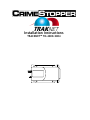
Installation Instructions
TRACKNET™ TN-4003/4004
TABLE OF CONTENTS
TABLE OF CONTENTS
Introduction .................................................................................................................................... 2
Installation Caution and Warnings ............................................................................................... 3
Control Module and Components ............................................................................................. 3-4
Mounting Location………………………………………..................................................................4-5
Installations.................................................................................................................................. 6-7
LED Status Indicator........................................................................................................................ 8
Wiring…...................................................................................................................................... 9-10
Wiring Diagram………………........................................................................................................ 11
Access Information ...................................................................................................................... 12
2
INSTALLATION CAUTIONS & WARNINGS
BEFORE BEGINNING, check all vehicle manufacturer cautions and warnings
regarding electrical service (AIR BAGS, ABS BRAKES, ENGINE COMPUTERS, and
BATTERY etc.).
WE RECOMMEND the use of a VOLT/OHM METER to test and verify wiring circuits.
Test lights or illuminated probes can cause damage to on-board computer or engine
management systems.
DO NOT exceed maximum output ratings or damage may occur. Electrical
current limits for the TrakNet are listed where applicable on the system diagram. If
you are unsure about the current load, of a specific circuit on your vehicle, measure
the load first with an amp-meter before connecting.
WE RECOMMEND that the MAIN SYSTEM FUSE be REMOVED before jump
starting, using a battery charger, or changing the battery. A voltage surge or high
boost condition could damage alarm circuits.
DO NOT ROUTE ANY WIRING THAT MAY BECOME ENTANGLED with brake,
and gas pedals, steering column, or any other moving parts in the vehicle.
CONTROL MODULE & COMPONENT MOUNTING
DO NOT Mount the control unit in the engine compartment or where the
control unit or wiring harness where they can become entangled with moving
parts such as brake/gas/clutch pedals, or the steering column! The TrakNet
control module and back up battery should be mounted in a concealed location. The
antenna wire should be routed away from any metal if possible. Do not alter the
length of the antenna wire or route it with other wires. Do not ground the antenna
wire. Fasten the module to a bracket or wire harness using the cable ties. Under
dash Mounting: If you are locating the control unit under dash, mount it as high as
possible, not easily located.
Antenna: The antenna location must be selected carefully so that the antenna can
receive the satellite signals. The antenna is designed to be mounted inside the
vehicle. The ideal location is in a place that allows line of sight reception from the
GPS satellites. The antenna must be mounted flat with the GPS receiver facing up.
The ideal location is under the dashboard. It can be placed under the dash pad as
long as the covering is not metallic. The antenna works best if it has a clear view of
the sky. Do not mount antenna under a window that has metallic tint on it. This
will affect the reception of the unit.
3
CONTROL MODULE & COMPONENT MOUNTING
Main Unit: The TrakNet unit has an internal power management program that
monitors the vehicle power at all times. The internal power management program is
continuously looking at the condition of the battery in order to detect the state of the
vehicle operation. The Traknet unit determines the state of the vehicle power by
detecting changes in the battery voltage over time. It is critical that the vehicle power
be taken from a source as close to the battery as possible. Possible sources besides
a direct connection to the battery is the main fuse block.
Back Up Battery: Securely mount the battery so it wont move around. It can be
mounted in various positions because the battery is sealed and should not leak.
MOUNTING LOCATION
Module Mounting Location
The Traknet Unit is supplied with a 6 ft. power cable. The unit should be mounted so
it will not be exposed to damage from people or objects. The cables that connect to
the unit should also be routed to protect them from possible damage. The module
has a mounting base or flange with four mounting holes. Normal installation is with
these four holes and #6 or #8 sheet metal screws. The unit must be mounted where
it will not be exposed to direct sunlight or excessive heat generated by the vehicle
operation. Some examples of mounting locations include under the dash above the
knee bolster, under center console, behind glove compartment, and in the trunk. If
the optional battery is to be installed there should be room to mount the battery
within 1 ft of the module.
The unit has a diagnostic wire and LED that will be used to verify operation by the
installer. These items are normally not used by the owner.
4
MOUNTING LOCATION
Selecting the Antenna Locations
The Module requires two antennas elements. One antenna is for receiving GPS
signals from The Navistar GPS satellites. The second antenna is a radio
transceiver antenna that communicates with the Cellular network. The antenna
does not require a ground plane to function properly.
There are two antenna cables in addition to the main power harness that must be
connected to the TRAKNET, so be sure there is room to access the connectors for
installation and service. If an exterior installation location is required you will need to
use the optional antennas designed for exposure to the outside elements. The
GPS/RF Combo antenna must be mounted flat with the GPS Receiver faced up.
The ideal location is under the dashboard. It can be placed under the dash pad as
long as the pad or covering is not metallic or a barrier to the GPS satellite signals. If
the vehicle window has a solid dark coating around the edge, do not place the GPS
antenna behind the coating. The GPS signals will travel through the clear glass but
will be reduced if the window has any metallic coating or tint applied.
The GPS/RF Combo antenna will work best if it has a clear view to the sky and as
much of the horizon as possible. Any metallic objects between the antenna and the
satellites will degrade the signal and reduce
5
INSTALLATION
Locating Vehicle Power
The TRAKNET has an internal power management program that monitors the
vehicle power at all times. The internal power management program is continuously
looking at the condition of the vehicle battery in order to detect the state of the
vehicle operation. The TRAKNET determines the state of the vehicle power by
detecting changes in the battery voltage over time. It is critical in this installation that
the vehicle power be taken from a source as close to the battery as possible.
Possible sources besides the direct connection to the battery are the main fuse block
panel or the point where the vehicle charging circuits are connected to the 12-volt
system. a Connect the red lead or fuse end of the power cable to the +12 volt vehicle
power. The power cable can be shortened if needed but be sure to also install the in
line fuse. Connect the black lead to the vehicle chassis (ground). If you need to
shorten the power cable or reconnect the in-line fuse, the wires can be removed and
reattached by unscrewing the ends of the fuse holder and inserting the new wire.
The holder accepts a 1/ 4-inch striped stranded wire. Tighten the fuse holder ends by
securely tightening by hand.
*Improper connection could result in numerous “Start up test” notifications,
and increased usage on monthly billing.
Powering the Unit for the First Time
*Disconnect the backup battery if it is installed. Connect the two coax cables from
the combo antenna (securely) and connect the vehicle’s 12-volt power and observe
the LED on the Module. During the initial 15 minutes after +12 volts is connected to
the Module, the LED should flash green at the rate of 1 second “on”, 5 seconds “off”,
this feature is designed for installation test purposes (15 minute Start-Up).
6
INSTALLATION
Within five minutes the flash rate will change to approximately one second on and
one second off to indicate that the GPS Receiver has established a location “lock”.
Within 1 minute the flash color should be green to indicate good cellular coverage. If
you do not get the results above, refer to page 13, Section 13 – Troubleshooting
Confirming Proper Operation
The Test wire (see wiring diagram) on the TRAKNET is for testing the internal
functionality of the hardware. Running tests with this wire grounded will not send
data to the call center. The user account does not need to be activated to run the
tests. Grounding the wire will start test mode function. If the wire is not removed
from ground the unit will remain in the test mode for 5 minutes and then return to
normal operation. To start the tests again you must ground the test wire again. If
you want the TRAKNET to function normally after testing, remove the test wire
from ground and tape the end to prevent the device from going into test mode
during normal operation.
Remember that the TRAKNET will remain in the test mode for only 5 minutes at a
time and you will need to cycle the test wire to re-enter the test mode. The
TRAKNET interface circuits are all pre-wired in the cable harness. Table 1 also
shows the wire colors associated with the input and output circuits. The digital
outputs are provided to switch optional external devices. Each can sink 1 amp at 35
volts. The outputs are voltage protected so they can sink current from inductive
loads. If the individual sink current is allowed to exceed 1 amp, the outputs could be
damaged. The digital inputs are triggered by a contact closure or short of less than
100 ohms from the contact to ground on their inputs.
7
LED STATUS INDICATOR
LED Status Indicator
BI-COLOR ON BOARD LED: This unit has a bi-colored LED on unit.
SOLID LED COLOR:
Solid Green – Device is in Test Mode: no inputs are currently being triggered.
Solid Orange – Device is in Test Mode: At least one input is currently being
triggered.
Solid Red – Device is in set up mode
BLINKING LED COLOR:
Blinking Green – Microburst and Cellular Service are available.
Blinking Orange – Cellular Service, but not Microburst Service is available.
Blinking Red – Neither Cellular Service nor Microburst service is available.
BLINKING LED TIMING:
OFF FOR 1 SECOND
OFF FOR 5 SECONDS
OFF FOR 10 SECONDS
OFF FOR 21 SECONDS
OFF FOR 25 SECONDS
OFF FOR 30 SECONDS
GPS Module is powered and signal is Valid, Cell
Module is powered.
GPS Module is powered and signal is invalid, cell
module is powered.
GPS module is turned off, Cell module is powered.
GPS module is powered and signal is invalid, cell
module is turned off.
GPS module is powered and signal is invalid, Cell
module is turned off.
GPS module is turned off, Cell module is turned off.
NOTE: It is highly recommended to perform a location request and other
optional features before releasing the vehicle.
8
WIRING
NOTE: Some Options Need to Be Pre-programmed From Crimestopper prior to
installing the unit.
Pin 1 Black: Chassis Ground Input
THIS WIRE MUST BE CONNECTED TO THE CHASSIS METAL OF THE VEHICLE.
Scrape away any paint or dirt to ensure a good connection.
Pin 2 Green: Starter Disable (-) (Output #2) Requires Relay
This wire has a negative output to hook up to optional relay. See wiring diagram for
connection.
Pin 3 Blue: GEO Fence (Optional) (-) Input #2
Connect wire to momentary switch 2 sec input to trigger for GEO fence or 15 sec
input to trigger alarm.
Pin 4: Empty
Pin 5 Red: Battery Back Up Power (Input)
Pre-wired to connector for battery back up.
Pin 6 White: Overheat Trigger/ Road Side Assistance (-) Input #3
This wire needs 2 minute trigger for Overheat or 2 sec trigger for Road Side
Assistance. Pre-programmed for Overheat.
Pin 7: Empty
Pin 8 Brown: Ignition Input #4 (+)
This wire must be connected to an Ignition source.
Pin 9: Empty
Pin 10 Purple: LED (Optional) (+) Output
This wire connects to optional LED for visual status of RSA or GEO Fence.
Pin 11 Yellow: Door Unlock Output (-)
This wire connects to the door unlock circuit. This wire is a negative output and may
require additional relays to interface with different door lock circuits
9
WIRING
Pin 12 Orange: Alarm Trigger (-) Default* or Door Open/Close Input #1
A. Alarm Trigger*: Triggers alarm input of tracking device if received a negative
input for 15 seconds or longer. This is connected to the negative siren output, if
alarm has positive siren output use a relay to convert to negative.
B. Door Open/Close Input :This unit can be programmed for monitoring of door
open and close. This configuration must be program see dealer for
programming instructions.
Pin 13: Empty
Pin 14 Red: 12 Volts Input
This wire is the main power lead. It requires 12 volts constant power.
Pin15 Black: Chassis Ground Input
THIS WIRE MUST BE CONNECTED TO THE CHASSIS METAL OF THE VEHICLE.
Scrape away any paint or dirt to ensure a good connection.
Pin 16 Black Ground Input
This wire is ground input from the back up battery.
Pin 17 Gray (Not Used)
Pin 18 White/Brown (-) Output
This wire can be programmed to be a ½ second pulsed output or a 3 second pulsed
output.
Pin 19 Green/Yellow (-) Input
Ground this wire to trigger start up test on unit
PIN 20 White/Yellow (Not Used)
10
WIRING DIAGRAM
11
ACCESS INFORMATION
Congratulations, you have just installed the Internet based vehicle
telematics system. Now that it’s installed, here’s how to use your
system.
Step #1
First fill out your TrakNet registration form and fax to 805.581-9500. Then you will
receive a call or email with your login and password.
Step #2
Turn on your computer and log on to the Internet using your standard Internet
browser.
.
• Go to: www.nationstrack.com
.
• Enter customer login and password. Then click login.
You may now begin to enjoy all of your new TrakNet™ GPS systems features.
Vehicle location requests which provide a map display will generally appear on
average in about 30 seconds, your time may vary from 5 to 90 seconds depending
upon network signal strengths in your area.
This device complies with FCC Rules part 15. Operation is subject to the following two
conditions: 1) This device may not cause interference, and (2) this device must accept any
interference that may be received, including interference that may cause undesired
operation. Th e manufacturer is not responsible for any radio or TV interference caused by
unauthorized modification to this equipment. Such modification could void the user's
authority to operate the equipment.
Changes or modifications not expressly approved by Crimestopper Security Products, Inc. Could
void the user’s authority to operate the equipment.
Crimestopper Security Products Inc.
1770 So. Tapo Street
Simi Valley, CA 93063
(800) 998-6880
www.crimestopper.com
©2005 Crimestopper Security Products
ONLINE TECHNICAL SUPPORT
www.crimestopper.com