1
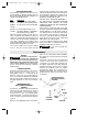
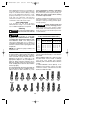
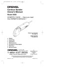
DM 2610919361 9/03
9/5/03
8:33 AM
Page 1
Contour Sander
Owner’s Manual
Model 6000
HONESTLY NOW … Have you read
this OWNER’S MANUAL?
Parlez-vous français?
Voir page 12
¿Habla español?
Vea página 23
•
•
•
•
•
•
•
Safety
Assembly
Operation
Maintenance
Accessory Information
Warranty
Service Parts
P.O. Box 1468
Racine, Wisconsin 53401
1-800-437-3635
http://www.dremel.com
©
Robert Bosch Tool
Corporation
1997
all rights reserved
Dremel brand products are manufactured and sold by the
Dremel Division of Robert Bosch Tool Corporation
2610925476 10/04
Printed in Mexico
DM 2610919361 9/03
9/5/03
8:33 AM
Page 2
Power Tool Safety Rules
! WARNING Read and understand all instructions. Failure to follow all instructions
listed below, may result in electric shock, fire and/or serious personal
injury.
SAVE THESE INSTRUCTIONS
Damaged cords increase the risk of electric
shock.
Work Area
Keep your work area clean and well lit.
Cluttered benches and dark areas invite
accidents.
When operating a power tool outside, use
an outdoor extension cord marked "W-A"
or "W." These cords are rated for outdoor
use and reduce the risk of electric shock.
Refer to “Recommended sizes of Extension
Cords” in the Accessory section of this
manual.
Do not operate power tools in explosive
atmospheres, such as in the presence of
flammable liquids, gases, or dust. Power
tools create sparks which may ignite the
dust or fumes.
Keep by-standers, children, and visitors
away while operating a power tool.
Distractions can cause you to lose control.
Personal Safety
Stay alert, watch what you are doing and
use common sense when operating a
power tool. Do not use tool while tired or
under the influence of drugs, alcohol, or
medication. A moment of inattention while
operating power tools may result in serious
personal injury.
Electrical Safety
Double Insulated tools are equipped with
a polarized plug (one blade is wider than
the other.) This plug will fit in a polarized
outlet only one way. If the plug does not
fit fully in the outlet, reverse the plug. If it
still does not fit, contact a qualified
electrician to install a polarized outlet. Do
not change the plug in any way. Double
Insulation
eliminates the need for the
three wire grounded power cord and
grounded power supply system. Before
plugging in the tool, be certain the outlet
voltage supplied is within the voltage marked
on the nameplate. Do not use “AC only”
rated tools with a DC power supply.
Dress properly. Do not wear loose
clothing or jewelry. Contain long hair.
Keep your hair, clothing, and gloves away
from moving parts. Loose clothes, jewelry,
or long hair can be caught in moving parts.
Keep handles dry, clean and free from oil
and grease.
Avoid accidental starting. Be sure switch
is “OFF” before plugging in. Carrying tools
with your finger on the switch or plugging in
tools that have the switch “ON” invites
accidents.
Avoid body contact with grounded
surfaces such as pipes, radiators, ranges
and refrigerators. There is an increased
risk of electric shock if your body is
grounded. If operating the power tool in
damp locations is unavoidable, a Ground
Fault Circuit Interrupter must be used to
supply the power to your tool. Electrician’s
rubber gloves and footwear will further
enhance your personal safety.
Remove adjusting keys or wrenches
before turning the tool “ON”. A wrench or
a key that is left attached to a rotating part of
the tool may result in personal injury.
Do not overreach. Keep proper footing
and balance at all times. Proper footing
and balance enables better control of the
tool in unexpected situations.
Use safety equipment. Always wear eye
protection. Dust mask, non-skid safety
shoes, hard hat, or hearing protection must
be used for appropriate conditions.
Don't expose power tools to rain or wet
conditions. Water entering a power tool will
increase the risk of electric shock.
Do not abuse the cord. Never use the
cord to carry the tools or pull the plug
from an outlet. Keep cord away from
heat, oil, sharp edges or moving parts.
Replace damaged cords immediately.
Tool Use and Care
Use clamps or other practical way to
secure and support the workpiece to a
stable platform. Holding the work by hand
-2-
DM 2610919361 9/03
9/5/03
8:33 AM
Page 3
Do not force tool. Use the correct tool for
your application. The correct tool will do
the job better and safer at the rate for which
it is designed.
other condition that may affect the tools
operation. If damaged, have the tool
serviced before using. Many accidents are
caused by poorly maintained tools. Develop
a periodic maintenance schedule for your
tool.
Do not use tool if switch does not turn it
“ON” or “OFF”. Any tool that cannot be
controlled with the switch is dangerous and
must be repaired.
Use only accessories that are
recommended by the manufacturer for
your model. Accessories that may be
suitable for one tool, may become hazardous
or against your body is unstable and may
lead to loss of control.
when used on another tool.
Disconnect the plug from the power
source before making any adjustments,
changing accessories, or storing the tool.
Such preventive safety measures reduce the
risk of starting the tool accidentally. Store
idle tools out of reach of children and
other untrained persons. Tools are
dangerous in the hands of untrained users.
Service
Tool service must be performed only by
qualified repair personnel. Service or
maintenance performed by unqualified
personnel could result in a risk of injury. For
example: internal wires may be misplaced or
pinched, safety guard return springs may be
improperly mounted.
Maintain tools with care. Keep cutting
tools sharp and clean. Properly maintained
tools, with sharp cutting edges are less likely
to bind and are easier to control. Any
alteration or modification is a misuse and
may result in a dangerous condition.
When servicing a tool, use only identical
replacement parts. Follow instructions in the
Maintenance section of this manual. Use of
unauthorized parts or failure to follow
Maintenance Instructions may create a risk of
electric shock or injury. Certain cleaning agents
such as gasoline, carbon tetrachloride,
ammonia, etc. may damage plastic parts.
Check for misalignment or binding of
moving parts, breakage of parts, and any
Contour Sander Safety Rules
clothing must be worn by all persons
entering the work area. Work area should be
sealed by plastic sheeting and persons not
protected should be kept out until work area
is thoroughly cleaned.
Unplug the sander before changing
accessories. Accidental start-ups may
occur if sander is plugged in while changing
an accessory.
If your tool is equipped with a dust bag,
empty it frequently and after completion
of sanding. Be extremely careful of dust
disposal, materials in fine particle form may
be explosive. Do not throw sanding dust on
an open fire. Spontaneous combustion, may
in time, result from mixture of oil or water
with dust particles.
Do not wet sand with this sander. Liquids
entering the motor housing is an electrical
shock hazard.
Do not use sandpaper intended for larger
sanding pads. Larger sandpaper will extend
beyond the sanding pad causing snagging,
tearing of the paper or kick-back. Extra
paper extending beyond the sanding pad
can also cause serious lacerations.
Always wear eye protection and a dust
mask for dusty applications and when
sanding overhead. Sanding particles can
be absorbed by your eyes and inhaled easily
and may cause health complications.
Clamp or secure workpiece when
sanding. Clamping the workpiece prevents
it from being ejected from under the sander
and leaves both hands free to control the
tool.
Use special precautions when sanding
chemically pressure treated lumber, paint
that may be lead based, or any other
materials that may contain carcinogens. A
suitable breathing respirator and protective
Keep the cord away from the accessory.
The cord can become entangled with the
pad or contour.
-3-
DM 2610919361 9/03
9/5/03
8:33 AM
Page 4
Some dust created by
• Arsenic and chromium from chemicallytreated lumber.
! WARNING power sanding, sawing,
grinding, drilling, and other construction
activities contains chemicals known to
cause cancer, birth defects or other
reproductive harm. Some examples of
these chemicals are:
Your risk from these exposures varies,
depending on how often you do this type of
work. To reduce your exposure to these
chemicals: work in a well ventilated area,
and work with approved safety equipment,
such as those dust masks that are specially
designed to filter out microscopic particles.
• Lead from lead-based paints,
• Crystalline silica from bricks and cement
and other masonry products, and
-4-
DM 2610919361 9/03
9/5/03
8:33 AM
Page 5
Symbols
IMPORTANT: Some of the following symbols may be used on your tool. Please study them
and learn their meaning. Proper interpretation of these symbols will allow you to operate the
tool better and safer.
Symbol
Name
Designation/Explanation
V
Volts
Voltage (potential)
A
Amperes
Current
Hz
Hertz
Frequency (cycles per second)
W
Watt
Power
kg
Kilograms
Weight
min
Minutes
Time
s
Seconds
Time
Diameter
Size of drill bits, grinding wheels, etc.
No load speed
Rotational speed, at no load
n0
.../min
0
1, 2, 3, ...
I, II, III,
0
Revolutions or reciprocation per minute Revolutions, strokes, surface speed,
orbits etc. per minute
Off position
Zero speed, zero torque...
Selector settings
Speed, torque or position settings.
Higher number means greater speed
Infinitely variable selector with off
Speed is increasing from 0 setting
Arrow
Action in the direction of arrow
Alternating current
Type or a characteristic of current
Direct current
Type or a characteristic of current
Alternating or direct current
Type or a characteristic of current
Class II construction
Designates Double Insulated
Construction tools.
Earthing terminal
Grounding terminal
Warning symbol
Alerts user to warning messages
Ni-Cad RBRC seal
Designates Ni-Cad battery recycling
program
This symbol designates
that this tool is listed to
Canadian Standards by
Underwriters Laboratories.
This symbol designates
that this tool is listed by
Underwriters Laboratories.
This symbol designates
that this tool is listed by
Underwriters Laboratories,
and listed to Canadian
Standards by Underwriters
Laboratories.
This symbol designates
that this tool is listed by
the Canadian Standards
Association.
-5-
This symbol
designates
that
this tool
complies
to NOM
Mexican
Standards.
DM 2610919361 9/03
9/5/03
8:33 AM
Page 6
Functional Description and Specifications
Disconnect the plug from the power source before making any
! WARNING assembly, adjustments or changing accessories. Such preventive safety
measures reduce the risk of starting the tool accidentally.
Contour Sander
FIG. 1
POWER CORD
MOTOR
BRUSHES
VENTILATION
OPENINGS
ON/OFF
SWITCH
VARIABLE
SPEED SWITCH
GRIP
DIMPLES
RELEASE
LEVER
SANDING
TUBE
CLAMP
HOLDER
CONTOUR
RUBBER
GRIP RING
DETAIL
PAD
HOOK & LOOP
PAPER
See diagram for proper way to
hold tool. The head of sander
will get warm as it is being
used. Please use care to make
sure ventilation openings are
not covered during use.
VENTILATION
OPENINGS
WARM AREA
NOTE: For tool specifications refer to the nameplate on your tool.
-6-
DM 2610919361 9/03
9/5/03
8:33 AM
Page 7
Operating Instructions
ON/OFF AND VARIABLE
SPEED SWITCHES
Your Sander is equipped with a variable
speed switch and a separate on/off switch.
The speed can be controlled from minimum
to maximum speed by moving the switch
lever to desired setting.
TO TURN TOOL “ON”: Slide switch to the
“ON”position (I) on symbol.
TO TURN TOOL “OFF” Slide switch to the
“OFF” position (0) off symbol.
TO INCREASE SPEED: Move variable speed
control lever toward the + sign.
TO DECREASE SPEED: Move variable speed
control lever toward the – sign.
Setting
Material/Application
Low
Delicate surfaces, veneers,
or light surface finishing &
polishing
Low
Plastics or other soft surfaces
Medium
Solid wood, fast stock
removal, paint removal
High
General use, metal sanding &
finishing, chipboard, coarse
sanding on rough surfaces,
& polishing
5. Press holder firmly back up into place
until the pad "snaps" into position.
SELECTING A CONTOUR SHAPE
Individual contour shapes are available in three
basic styles. A variety of radiuses are available
in each style:
To remove pad, rotate lever to release and
lower the clamp holder. Remove the pad
from the holder. You are now ready to install
another pad or contour shape.
Convex shapes: 1/8", 3/16", 1/4", 3/8", 1/2",
5/8"
Concave shapes: 1/8", 3/16", 1/4", 3/8", 1/2",
5/8"
When using detail sanding pads, regularly
rotate the pad 180 degrees to maximize all
surfaces for longer, more efficient use.
Angled shapes: Flat, 30°, 60°, 45°, 90°, -90°
The contour shapes are available in a variety of
different radiuses to match common
configurations. Additionally, each contour can
be modified or customized by trimming or
shaping the material to the desired form.
INSTALLING AND REMOVING
CONTOURS
To attach a contour shape to the sander:
INSTALLING AND REMOVING DETAIL
PAD & OPTIONAL SHUTTER PAD
Your sander is equipped with a quick change
clamping mechanism that allows you to easily
change accessories without additional tools.
2. Rotate red release lever to lower the
accessory clamp holder.
1. Disconnect sander from power source.
3. Apply either a sanding tube or pressure
sensitive adhesive directly to contour shape.
4. Insert contour completely into the top and
back of the holder until it reaches the rear
"stop" (Fig. 2).
To attach detail pad or optional shutter pad to
the sander:
1. Disconnect sander from power source.
CONTOUR
2. Rotate red release lever to lower the
accessory clamp holder.
3. Apply hook and loop backed sandpaper to
pad.
FIG. 2
CLAMP
HOLDER
4. Insert pad completely into the top and
back of the holder until it reaches the rear
"stop".
REAR
STOP
HINT: Make sure the small grip dimples have
firmly secured the rubber grip ring (Fig. 1).
RELEASE LEVER
-7-
DM 2610919361 9/03
9/5/03
8:33 AM
Page 8
Operating Instructions (cont.)
Hint: make sure the small grip dimples have
firmly secured the sandpaper surface.
5. Press holder firmly back up into place
until the contour "snaps" in place.
To remove contour, rotate lever to release
and lower the clamp holder. You are now
ready to install another contour shape or
detail pad.
When using sanding tubes, rotate them
regularly to maximize all surfaces for longer,
more efficient use.
HINT: When reaching into extremely tight
places, the contour can be extended beyond
the front of the tool.
NOTE: DO NOT APPLY EXCESSIVE
PRESSURE TO THE TOOL WHILE IN USE.
ALLOW THE SPEED OF THE TOOL AND THE
ACCESSORY TO DO THE WORK. APPLYING
UNNECESSARY PRESSURE WILL CAUSE
THE ACCESSORY TO WEAR UNEVENLY - IT
WILL NOT SERVE TO PERFORM THE WORK
MORE QUICKLY.
“Accessory Tips”
Contours: Use sanding tubes that are long
lasting, reusable and easy to install. To
install, slide tube completely over desired
contour, and shape paper to contour.
Contour abrasive tubes can also be rotated
on the contour, to maximize the use of the
abrasive surface.
NOTE: The contour shapes have been
extruded to the dimension indicated on the
shape. When doing exacting work, it will be
necessary to provide an allowance for the
sandpaper being used. Heavier/coarser grit
papers require a greater allowance.
PSA Adhesives work best at temperatures
above 25 degrees F. If PSA abrasives and
pads are stored at lower temperatures, it may
be necessary to allow them to come to room
temperature before use.
PSA Rolls: Rolls with pressure sensitive
adhesive can also be used with individual
contours. Unroll a strip of abrasive to fit the
particular contour, and cut to length with
scissors. When using pressure sensitive
adhesive, optimal clamping can be obtained
if the entire contour surface is wrapped with
paper. Firmly press the abrasive in place on
the contour. To remove abrasive, lift a
corner of the sheet with your fingernail and
peel it off. Dispose of the used abrasives,
they are not reusable.
PSA Rolls must be stored in a dust-free
environment to prevent contamination of
adhesive.
After considerable use, the detail pad backing
surface may become worn. The backing pad
must be replaced when it no longer offers a
firm grip. If you are experiencing premature
wearout of the backing pad facing, decrease
the amount of pressure you are applying
during operation of the tool.
HINT: When using 1/8" and 3/16" concave
contours with sanding tubes, it will be easier to
conform the abrasive to the workpiece if a finer
grit paper is used.
“Tool Tips”
Always be certain that smaller workpieces are
securely fastened to a bench or other support.
Larger panels may be held in place by hand on
a bench or sawhorse.
SANDING: Open-coat aluminum oxide sanding
sheets are recommended for most wood or
metal sanding applications, as this synthetic
material cuts quickly and wears well.
This machine is particularly suitable for access
to corners and edges that are otherwise
difficult to reach or require hand sanding.
Profiles and grooves may be finished using the
tip or edge of the selected accessory, which
should occasionally be rotated during use to
distribute the wear on the accessory or
backing pad surface.
-8-
DM 2610919361 9/03
9/5/03
8:33 AM
Page 9
SELECTING ABRASIVES
The following suggestions may be used as a
general guide for abrasive selection, but the
best results will be obtained by sanding a test
sample of the workpiece first.
Grit
Coarse
80 grit
Medium
120 grit
Extra fine
220 grit
Application
For rough wood, metal sanding,
rust, paint, or old material removal.
For general wood or metal sanding.
For final sanding of bare wood,
smoothing old paint, or preparing a
finished surface for recoating.
With the workpiece firmly secured, turn tool
“ON”. Contact the work with the tool after the
sander has reached the selected speed, and
remove it from the work before switching the
tool “OFF”. Operating your sander in this
manner will prolong switch and motor life, and
greatly increase the quality of your work.
Your contour sander uses an in-line sanding
motion. The best surface finish will be
achieved while operating the sander in-line
with the wood grain. Faster stock removal can
be achieved by operating the sander across
the grain when working out rough areas, then
finishing by sanding with the grain.
DO NOT APPLY EXCESSIVE PRESSURE —
LET THE TOOL DO THE WORK. EXCESSIVE
PRESSURE WILL RESULT IN POOR
HANDLING, VIBRATION, AND UNWANTED
SANDING MARKS.
If the surface is rough, begin with coarser grits
and then complete the surfacing with medium
and fine abrasives. To avoid uneven results, do
not skip more than one grit size when going
from coarser to finer, and do not sand in one
area for too long. When the job is completed,
gently lift the tool from the work surface and
slide switch to the "OFF" position.
To ensure longer life and even wear, lightly
brush any residue or clogged materials from
sandpaper surface prior to each use.
Do not wet sand with this
! WARNING
sander.
Maintenance
caps one at a time with a small screwdriver
by rotating cap counter-clockwise and check
each brush.
If the brush is less than 1/8" long and the end
surface of the brush that contacts the
commutator is rough and/or pitted, they
should be replaced. Check both brushes.
Usually the brushes will not wear out simultaneously. If one brush is worn out, replace
both brushes. Make sure the brushes are
installed as illustrated. The curved surface of
the brush must match the curvature of the
commutator.
Service
Preventive maintenance
! WARNING performed by unauthorized
personnel may result in misplacing of
internal wires and components which could
cause serious hazard. We recommend that
all tool service be performed by a Dremel
Service Facility.
CARBON BRUSHES
The brushes and commutator in your tool have
been engineered for many hours of
dependable service. To maintain peak
efficiency of the motor, we recommend every
two to six months the brushes be examined.
Only genuine Dremel replacement brushes
specially designed for your tool should be
used.
CURVED END OF BRUSH
MUST MATCH CURVATURE
OF HOUSING
MAINTENANCE OF
REPLACEABLE BRUSHES
#5090930
The brushes should be inspected frequently
when tools are used continuously. If your tool
runs sporadically, loses power, makes
unusual noises or runs at a reduced speed,
check the brushes. To continue using the tool
in this condition will permanently damage
your tool.
BRUSH
WASHER
CURVATURE
OF HOUSING
BRUSH
SPRING
BRUSH CAP
With the cord unplugged, remove the brush
-9-
DM 2610919361 9/03
9/5/03
8:33 AM
Page 10
After replacing brushes the tool should be run
at no-load; place on a clean surface and run
freely for 5 minutes before loading (or using)
the tool. This will allow the brushes to “seat”
properly and will give you more hours of life
from each set of brushes. This will also
extend the total life of your tool since the
commutator surface will “wear” longer.
TOOL LUBRICATION
Your Dremel tool has been properly
lubricated and is ready to use. Under normal
use no additional lubrication is required.
Cleaning
To avoid accidents always
! WARNING disconnect the tool from the
power supply before cleaning or performing
any maintenance. The tool may be cleaned
most effectively with compressed dry air.
Always wear safety goggles when cleaning
tools with compressed air.
Ventilation openings and switch levers must be
kept clean and free of foreign matter. Do not
attempt to clean by inserting pointed objects
through openings.
!
parts. Some of these are: gasoline, carbon
tetrachloride, chlorinated cleaning solvents,
ammonia and household detergents that
contain ammonia.
If an extension cord is
RECOMMENDED SIZES OF EXTENSION CORDS
120 VOLT ALTERNATING CURRENT TOOLS
! WARNING necessary, a cord with
adequate size conductors that is capable
of carrying the current necessary for your
tool must be used. This will prevent
excessive voltage drop, loss of power or
overheating. Grounded tools must use 3-wire
extension cords that have 3-prong plugs and
receptacles.
Tool’s
Ampere
Rating
3-6
6-8
8-10
10-12
12-16
NOTE: The smaller the gauge number, the
heavier the cord.
Your Contour Sander can be equipped with
an optional dust collection wand. This device
is effective in sanding pad dust collection
when used with a shop vacuum with hose
dimensions of ID 1-1/2” or OD 1-3/8” or an
appropriate adapter to fit (see diagram on
page 31). When using the wand, be sure to
align the sanding sheet holes with the holes
in the sanding pad to allow the dust wand to
function properly.
The detail pad (and optional shutter pad) can
be used with hook/loop sandpaper with or
without holes for dust collection. If you’ve
#6017
1/8"
#6018
3/16"
#6019
1/4"
#6020
3/8"
Certain cleaning agents and
CAUTION solvents damage plastic
Cord Size in A.W.G.
Wire Sizes in mm2
Cord Length in Feet
Cord Length in Meters
25
50
100 150
15
30
60
120
18
18
18
16
14
16
16
16
16
12
16
14
14
14
—
.75
.75
.75
1.0
—
.75
1.0
1.0
2.5
—
1.5
2.5
2.5
4.0
—
2.5
4.0
4.0
—
—
14
12
12
12
—
purchased sandpaper without holes, holes
can be punched manually for use with the
dust wand.
Using sandpaper with holes - while not using
the dust wand - will not harm or damage
your work. This sander will operate
effectively with or without the dust collection
system.
To order individual contours (below), or for
additional information about the dust
collection feature, call Dremel Customer
Service @ 1-800-437-3635.
#6021
1/2"
#6022
5/8"
#6023
1/8"
#6024
3/16"
#6025
1/4"
Radius
#6026
3/8"
#6027
1/2"
#6028
5/8"
#6029
Flat
#6030
30º
-10-
#6031
45º
#6032
60º
#6033
90º
#6034
90º
DM 2610919361 9/03
9/5/03
8:33 AM
Page 11
Dremel Limited Warranty
Your Dremel product is warranted against defective material or workmanship for a period of two
years from date of purchase. In the event of a failure of a product to conform to this written warranty,
please take the following action:
1. DO NOT return your product to the place of purchase.
2. Carefully package the product by itself, with no other items, and return it, freight prepaid, along
with:
A. A copy of your dated proof of purchase (please keep a copy for yourself).
B. A written statement about the nature of the problem.
C. Your name, address and phone number to:
UNITED STATES
Dremel Service Center
4915 Twenty-First Street
Racine, Wisconsin 53406
Dremel Service Center
4631 E. Sunny Dunes
Palm Springs, CA 92264
OR
CANADA
Giles Tool Agency
6520 Lawrence Av. East
Scarborough, Ont.
Canada M1C 4A7
OUTSIDE
CONTINENTAL UNITED STATES
See your local distributor or write
to Dremel, 4915 Twenty-First St.
Racine, Wisconsin 53406
We recommend that the package be insured against loss or in transit damage for which we cannot be
responsible.
This warranty applies only to the original registered purchaser. DAMAGE TO THE PRODUCT
RESULTING FROM TAMPERING, ACCIDENT, ABUSE, NEGLIGENCE, UNAUTHORIZED REPAIRS OR
ALTERATIONS, UNAPPROVED ATTACHMENTS OR OTHER CAUSES UNRELATED TO PROBLEMS
WITH MATERIAL OR WORKMANSHIP ARE NOT COVERED BY THIS WARRANTY.
No employee, agent, dealer or other person is authorized to give any warranties on behalf of Dremel.
If Dremel inspection shows that the problem was caused by problems with material or workmanship
within the limitations of the warranty, Dremel will repair or replace the product free of charge and
return product prepaid. Repairs made necessary by normal wear or abuse, or repair for product
outside the warranty period, if they can be made, will be charged at regular factory prices.
DREMEL MAKES NO OTHER WARRANTY OF ANY KIND WHATEVER, EXPRESSED OR IMPLIED, AND
ALL IMPLIED WARRANTIES OF MERCHANTABILITY AND FITNESS FOR A PARTICULAR PURPOSE
WHICH EXCEED THE ABOVE MENTIONED OBLIGATION ARE HEREBY DISCLAIMED BY DREMEL AND
EXCLUDED FROM THIS LIMITED WARRANTY.
This warranty gives you specific legal rights and you may also have other rights which vary from state to
state. The obligation of the warrantor is solely to repair or replace the product. The warrantor is not liable
for any incidental or consequential damages due to any such alleged defect. Some states do not allow the
exclusion or limitation of incidental or consequential damages, so the above limitations or exclusion may
not apply to you.
For prices and warranty fulfillment in the continental United States, contact your local Dremel distributor.
Exportado por: Robert Bosch Tool Corporation Mt. Prospect, IL 60056 -2230, E.U.A.
Importado en México por: Robert Bosch, S.A. de C.V., Calle Robert Bosch No. 405, Zona Industrial,
Toluca, Edo. de México, C.P. 50070, Tel. (722) 2792300
-11-