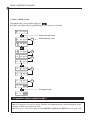
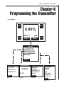
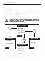
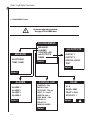
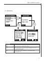
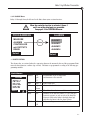
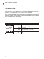
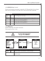
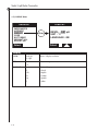
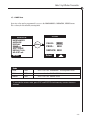
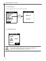
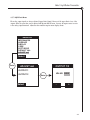
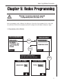
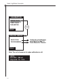
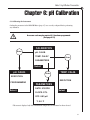
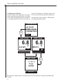
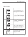
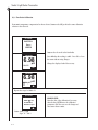
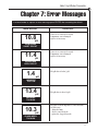
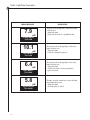
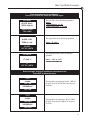
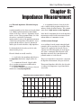
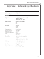
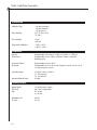
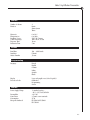
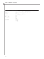
1
Instruction
Manual
QUICK GUIDE
• Wiring Diagram
Page 2-5
• Programming
the Display
Page 14• Calibration
Chapter 6
• Troubleshooting
Chapter 7
Model 14
pH/Redox Transmitter
Doc No. L2551 11/00
19 Thomas, Irvine, California 92618 USA
Call Toll-Free: 877.246.7900 (USA & Canada)
Phone: 949.452.1112 Fax: 949.452.1114
E-Mail: [email protected]
Model 14 pH/Redox Transmitter
Broadley Technologies Corporation
19 Thomas
Irvine, California 92618
USA
Corporate Headquarters:
Toll-Free: 877.246.7900
Tel: 949.452.1112 Fax: 949.452.1114
E-Mail: [email protected]
Website: www.biotechcatalog.com
Copyright © 2000 Broadley Technologies Corporation
All Rights Reserved
Model 14 pH/Redox Transmitter
Table of Contents
Chapter 1: Introduction .....................................................................................................................1-1
1.1 Introduction..............................................................................................................................................1-1
1.2 pH Measurement ......................................................................................................................................1-1
1.3 Redox Measurement .................................................................................................................................1-2
1.4 Main Features of the Instrument ...............................................................................................................1-2
1.5 Dimensions...............................................................................................................................................1-3
Chapter 2: Installation of the Instrument...........................................................................................2-1
2.1 Unpacking the Instrument.........................................................................................................................2-1
2.2 Installation Requirements .........................................................................................................................2-1
2.3 Mounting Options .....................................................................................................................................2-1
2.4 Electrical Connections ..............................................................................................................................2-4
2.5 Terminal Descriptions...............................................................................................................................2-5
2.6 Power Connection.....................................................................................................................................2-6
2.7 Measuring Line .........................................................................................................................................2-6
2.8 Starting the Transmitter.............................................................................................................................2-6
2.9 Adjusting the Display Contrast...................................................................................................................2-6
2.10 Changing the Programming Language .....................................................................................................2-7
Chapter 3: Front Panel Display ..........................................................................................................3-1
3.1 Front Panel Keys ....................................................................................................................................3-1
3.2 Displays 1 through 4..............................................................................................................................3-2
3.3 Description of the Function Keys............................................................................................................3-3
3.4 Icons......................................................................................................................................................3-3
3.5 Enter or Modify a Value .........................................................................................................................3-4
Chapter 4: Programming the Instrument............................................................................................4-1
4.1 Main Menu ............................................................................................................................................4-1
4.2 CALIBRATION Menu...............................................................................................................................4-2
4.3 MAINTENANCE Menu ............................................................................................................................4-3
4.4 PROGRAMMING Menu ...........................................................................................................................4-4
4.4.1 MEASURE Menu.............................................................................................................................4-5
4.4.2 ALARMS Menu ...............................................................................................................................4-7
4.4.3 CONTROLLER Menu.....................................................................................................................4-10
4.4.4 mA OUTPUTS Menu .....................................................................................................................4-12
4.4.5 RS485 Menu................................................................................................................................4-13
4.5 SERVICE Menu .....................................................................................................................................4-15
4.5.1 IMPEDANCES Menu ....................................................................................................................4-17
4.5.2 AVERAGE Menu ...........................................................................................................................4-17
4.5.3 DISPLAY Menu ............................................................................................................................4-18
4.5.4 CODE Menu ................................................................................................................................4-19
4.5.5 SOFT ISSUE Menu .......................................................................................................................4-20
i
Model 14 pH/Redox Transmitter
Table of Contents
(Continued)
Chapter 4: Programming the Instrument (continued)........................................................................4-1
4.5 SERVICE Menu (continued).................................................................................................................4-15
4.5.6 DEFAULT VALUES Menu ...............................................................................................................4-20
4.5.7 ADJUST mA Menu .......................................................................................................................4-21
Chapter 5 : Redox Programming ........................................................................................................5-1
Chapter 6: pH Calibration ..................................................................................................................6.1
6.1 Calibrating the Instrument ..................................................................................................................6-1
6.2 Temperature Calibration .....................................................................................................................6-2
6.3 pH Calibration ....................................................................................................................................6-3
6.3.1 Two-Point Calibration.................................................................................................................6-4
Chapter 7 : Error Messages................................................................................................................7-1
Chapter 8 : Impedance measurement.................................................................................................8-1
8.1 Electrode Impedance.......................................................................................................................8-1
8.2 Measurement Principle....................................................................................................................8-1
Appendix 1: Technical Specifications .................................................................................................A-1
Appendix 2: Default Values ................................................................................................................B-1
Appendix 3: Temperature Conversion Chart.......................................................................................C-1
ii
Model 14 pH/Redox Transmitter
Chapter 1: Introduction
reference electrodes
R = gas constant
The Model 14 pH/Redox transmitter has been designed T = temperature in Kelvin
for measuring and continuously controlling pH or a[H+] = activity of the hydrogen ion (assumed to
redox potential and temperature in industrial process. be equivalent to the concentration of hydrogen ions)
F = Faraday constant
1.2 pH Measurement
For every unit change in pH (or decade change in ion
concentration) the emf of the electrode pair changes by
Theory
59.16 mV at 25˚C. This value is known as the Nernstian
The pH of a solution is the measurment of the acidity, slope of the electrode.
or alkalinity of that solution. It is determined by the
negative logarithm of the hydrogen ion activity: pH = - The pH electrode pair is calibrated using solutions
log10 a[H+]
of known and constant hydrogen ion concentration,
called buffer solutions. The buffer solutions are used to
Two electrodes, glass electrode and a reference are calibrate both the electrode’s isopotential and slope.
used to measure pH. The glass electrode acts as a
transducer, converting chemical energy (the hydrogen
activity) into an electrical energy (measured in milli- 1.3 Redox Measurement
volts). The reaction is balanced and the electrical circuit is completed by the flow of ions from the reference A redox measuring system consists of a redox and a refsolution through the measured solution.
erence electrode. The measured redox potential is the
ratio of electrode activities and the number of transThe electrode and reference solution together develop ferred electrons. In many cases the pH of the solution
a voltage (emf) whose magnitude depends on four will influence the potential, too.
things:
The half-cell potential eB, of the reference electrode
• the type of reference electrode
will strongly influence the potential E of the measuring
• the internal construction of the glass electrode
chain. To remove this influence the potential of the
• the pH of the solution
measuring electrode can be related to the hydrogen
• the temperature of the solution.
electrode. If eB is the half-cell potential of the reference
electrode used, the calculation is made by
This electrode voltage is expressed by the Nernst equation:
e(H) = E + e B
1.1 Introduction
E = Eo - (2.3 R I) log a[H+]
E = Eo - (slope) log a[H+]
Such standardized redox potentials provide information to some extent on the oxidizing or reducing power
of a redox system. Increasing positive values express an
increasing power of oxidation. The more negative the
Where:
potential, the stronger the reducing power will be. The
E = the emf of the cell
Eo = the zero potential (isopotential) of the system: range of practical interest is between +1500 and -1000
depends on the internal construction of the glass and mV. Standard potentials of a redox system will be found
1-1
Model 14 pH/Redox Transmitter
for aOx = a Red and for pH = 0 which correspond to a Consumption
standardized hydrogen ion activity a[H+] = 1 mole per
liter. The stability and reversibility of a redox system Measuring Ranges
strongly influence the reproducibility of the measured
redox potential.
1.4 Main Features of the Instrument
2.5 mm2 screw terminal pulledout for the relays and power
supply
Weight
2 kg
Sensor interrogation is a standard feature on the Model
14. To utilize this function, the pH electrode should be Package
equipped with a ground. The Model 14 is also equipped with 2 analog outputs (0 4-20 mA).
Power Supply
1-2
• Standard version :
- 90.265 VAC 50/60 Hz
• Low voltage version :
- 13 – 30 VAC 50/60 Hz
- 18 – 42 VDC
pH : 0 – 14
ORP (redox) : ±1500 mV
temperature : -20 – 200˚C
(-4 – 392˚F)
Connections
The Model 14 is equipped with a single input measurement channel: a pH or redox sensor may be connected
in addition to a temperature Pt100 or Pt1000 probe.
Specifications (see Appendix 1 for detailed
specifications):
25 VA
Includes instruction manual,
4 cable glands, 2 fittings and
2 mounting screws
Conformance to
EN 50081-1 & EN 50082-2(RFI)
European Electrical EN 61010-1 (low voltage
Standards
directive)
Maintenance
No particular maintenance
required. Clean the instrument
with a soft tissue. Do NOT use
any aggressive agent.
Model 14 pH/Redox Transmitter
1.5 Dimensions
(Dimensions are in mm [inches]).
144 mm 5.669"
24 mm 0.945"
Esc
28 mm 1.102"
2 Pg13
Enter
73 mm 2.874"
144 mm 5.669"
117 mm 4.606"
24 mm 0.936"
33.5 mm 1.319"
2 Pg11
1-3
Model 14 pH/Redox Transmitter
1-4
Model 14 pH/Redox Transmitter
Chapter 2:
Installation of the Instrument
2.1 Unpacking the Instrument
2.2 Installation Requirements
The analyzer should be unpacked with great care. The analyzer should be located in a site, which permits
Watch for any loose accessories. Confirm the instru- access for inspection or maintenance operations.
ment includes: instruction manual, certificate of con- Choose a site which meets the following criteria:
formity, 4 cable glands, 2 fittings and 2 mounting
screws.
-No excessive vibrations
-Away from direct sunlight or other outdoor
exposure
The analyzer has been factory-checked and tested prior
-Ambient temperature and humidity are within
to shipment. It is advisable, however, to inspect all
specifications
parts immediately upon receipt for any damage which
may have occurred during shipment. A damaged shipping container may indicate internal damage, which Note: It is preferable to mount the instrument above
may not be immediately obvious. If there is any evi- eye level, allowing unrestricted view of the front panel
dence of damage, keep the shipping container and displays and controls.
refer to your local agent or to:
Broadley Technologies Corporation
19 Thomas
Irvine, CA 92618 USA
877-246-7900
2.3 Mounting Options (using the red clamping
bow)
The transmitter housing conforms to norm DIN 43700.
CAUTION!
Mounting should be done by qualified
service personnel only. No power should
be applied until the installation is complete.
2-1
Model 14 pH/Redox Transmitter
8 mm (0.315”) max.
Panel mounting
Panel cutout: 138 mm x 138 mm (5.4” x 5.4”)
Front panel dimensions: 144 mm x 144 mm (5.7” x 5.7”)
Included hardware: 2 flat head screws, 4 mm x 18 mm long, for panels up to 6 mm thick
285 mm (11.22”) max.
(a)
Wall mounting
Included hardware: (a) 2 pan head screws, 4 mm x 60 mm long for red clamping bow
Additional required hardware: (b) 2 flat head screws, 4 mm x 60 mm long
80 mm (3.15”) on center
2-2
80 (3.15)
04 (0,157)
(b)
Model 14 pH/Redox Transmitter
Vertical pipe mounting
Included hardware: 2 pan head screws,
4 mm x 60 mm long for red clamping bow
42 mm (1.653") max.
320 mm (12.598") max.
Horizontal pipe mounting
Included hardware: 2 pan head screws,
4 mm x 60 mm long for red clamping bow
2-3
Model 14 pH/Redox Transmitter
2.4 Electrical Connections
■ Model 14
Do not switch the instrument on until completion of the installation.
An aluminum armor plate inside the Model 14 gives a detailed description of the different terminals and their
connections:
➯ The Relay and Main Power terminals represented on the right side are accessible by removing
the aluminum plate.
Preamp.
Supply
+
l1
S1
Relays
+
l2
S2
S3 / Sys.Alarm
RX / TX +
RX / TX
S4 / Timer
Temp +
Temp
Input
GND
Ref.
GND
Liq.
Earth
+V
GND
-V
T 2A L
F1
PE
Mains
pH module
RS485
(option)
Analog
Outputs
Serial N°:
50 / 60Hz
N
L
25VA
Vac: 90...265V
Zellweger Analytics SA / F-93165 Noisy-le-Grand
Made in the E.E.C
RS486 Board (Optional)
Relay Board (Optional)
Contrast
Adjustment
pH Module
Power Supply Board
(Optional)
Programmed Eprom
2-4
Model 14 pH/Redox Transmitter
2.5 Terminal Descriptions
+
+
1
2
RS485
(option)
Analog
Outputs
0/4 - 20 mA outputs
galvanic insulation
pH module
RX/TX+
RX/TX-
Temp+
TempInput
Ref.
Liquid
Earth
Preamp
Supply
GND
GND
Description
0 - 20 mA or 4 - 20 mA (n°1) [+]
0 - 20 mA or 4 - 20 mA (n°1) [-]
0 - 20 mA or 4 - 20 mA (n°2) [-]
0 - 20 mA or 4 - 20 mA (n°2) [+]
Connection
user
user
user
user
RS485 Option
user
user
Connection
temp +
temp pH
Description
Temperature sensor [+]
Temperature sensor [-]
Input
Color
black
blue
Clear
Ref.
Liquid Earth
red
Reference
N.C.
Internal shield
brown
Ground
+V
GND
-V
N.C.
Mains
Behind aluminum plate
PE
N
L
Relays
S1
S2
S3/Sys. Alarm
S4/Timer
Main power supply, 90–265 VAC 50/60 Hz
or 24 V AC/DC (special version)
Description
Alarm 1, simple contact
Alarm 2, simple contact
Alarm 3 or alarm system, simple contact
Alarm 4 or timer, simple contact
Green (Ground)
White
Black
Connection
user
user
user
user
➯ Electrical connections should remain dry to ensure proper operation of the instrument.
Check the creeping of the cables when opening the transmitter.
➯ It is required to use shielded cables. This shielding should be connected to the earth
central shielding.
2-5
Model 14 pH/Redox Transmitter
2.6 Power Connection
2.7 Measuring Line
For safety reasons, it is required to observe the precau- The Model 14 transmitter should be connected to an
tions below:
electrode via a shielded cable.
1. The instrument should be connected to the power 2.8 Starting the Transmitter
supply by means of a breaker located close to the
instrument and clearly identified.
Before switching on the transmitter, make sure the site
voltage corresponds to the instrument voltage indicated
2. This breaker should switch off phase and neutral in on the identification plate. The electrode must be
case of electrical problems or to service the instru- immersed in the measuring sample or a buffer solution
ment. However, the earth ground must always be con- before measuring.
nected.
2.9 Adjusting the Display Contrast
2-6
Before servicing the instrument,
confirm the power supply is “off”.
If the display contrast is not sufficient, adjust the potentiometer P1 (blue color, see figure on page 2-4), which
is located on the top left of the CPU board (after opening the enclosure).
Model 14 pH/Redox Transmitter
2.10 Changing the Programming Language
The default programming language is English. To change the language,
follow the procedure below (example for French):
MENU
6.86%
23.2°C
Disp2
CALIBRATION
MAINTENANCE
PROGRAMMING
SERVICE
pH
Select
Menu
Enter
SERVICE
DISPLAY
Enter
RESOL.: 0.1pH
TEMP.: °C
LANGUAGE: GB
Select
AVERAGE
DISPLAY
CODE
SOFT ISSUE
DEFAULT VAL.
ADJUST mA
CONFIGURATION
Select
DISPLAY
DISPLAY
CONC: ppm
TEMP.: °C
PRESSURE: mmHg
LANGUAGE: F
CONC: ppm
TEMP.: °C
PRESSION: mmHg
LANGUE: F
Select
Enter
Esc
(press 3 times)
Select
2-7
Model 14 pH/Redox Transmitter
2-8
Model 14 pH/Redox Transmitter
Chapter 3:
Front Panel Displays
3.1 Front Panel Keys
Figure 3-1 : Front panel
3-1
Model 14 pH/Redox Transmitter
3.2 Displays 1 to 4 (live displays)
S1
6.86
S3
23.2°C : temperature measurement
S1...S4 : alarm status
(invisible if alarm is inactive)
pH
S2
S1
23.2°C
Disp2
Menu
S1: ˚C >30.0
S2: OK
S3: pH >14
S4: Not Used
Disp3
Main
Impedances
Glass
Reference
Main
3-2
S4
S3
S1...S4 : alarm status
In this case relays S1 and S3 are active
Main
I1: Measure
4.9 mA
I2: Temp
Disp4
6.86% : pH measurement
(or MV for redox)
Analog output allocation and level.
Displays output value with a bargraph
and numeric indication.
Model 14 pH/Redox Transmitter
3.3 Description of the Function Keys
The function keys vary depending on the menu. Each of the function keys below will be highlighted at the
bottom of the screen :
Modify a parameter
Select
Choose a menu
Main
Go back to the main display
Menu
Display the main menu
Disp2
Display screen 2
Disp3
Display screen 3
Disp4
Display screen 4
OK
Validate the measurement during calibration
Yes
Confirm a command
-
Increase a value
+
Decrease a value
S1
Action on relay S1
S2
Action on relay S2
3.4 Icons
Symbol of waiting or instrument reset
Alarm system for relay S3
Timer Symbol : countdown for relay S4
P
Controller Symbol
3-3
Model 14 pH/Redox Transmitter
3.5 Enter or Modify a Value
The highlighted digit can be modified with the key .
Each digit can be validated by pressing ENTER. Repeat both operations for each digit.
03.89 ppm
Increase the digit value
13.89 ppm
Enter
Validate the digit value
13.89 ppm
15.89 ppm
15.89 ppm
Enter
Enter
15.89 ppm
15.39 ppm
Enter
15.39 ppm
15.37 ppm
Enter
15.37 ppm
To change the unit
15.37 ppm
It is possible to display a negative first digit “-”
Note 1: If a menu is not accessed for at least 10 minutes, the instrument returns to the measuring mode except
during the calibration and maintenance mode.
Note 2: An access code may be required for the CALIBRATION, PROGRAM and SERVICE menus (see page 4-19).
3-4
Model 14 pH/Redox Transmitter
Chapter 4:
Programming the Transmitter
4.1 Main Menu
S1
S3
6.86%
23.2°C
S2
pH
Disp2
Menu
S4
MENU
CALIBRATION
MAINTENANCE
PROGRAMMING
SERVICE
Select
CALIBRATION
pH. CALIB.
TEMP. CALIB.
MAINTENANCE
6.98 pH
PARAMETERS
23.2°C
Select
Page 4-2
PROGRAMMING
MEASURE
ALARMS
CONTROLLER
mA OUTPUTS
RS485
Select
Page 4-3
Page 4-4
SERVICE
IMPEDENCES
AVERAGE
DISPLAY
CODE
SOFT ISSUE
DEFAULT VAL.
ADJUST mA
Select
Page 4-15
4-1
Model 14 pH/Redox Transmitter
4.2 CALIBRATION Menus
Before any calibration, confirm that the parameters are correctly configured in the MEASURE Menu, page 4-5.
All calibrations should follow the procedures below:
1. Configure the calibration characteristics in the “PROGRAMMING” menu.
2. Perform the calibration via the “EXECUTION” menu.
An access code may be required if it has been programmed. See page 4-19 for
CODE menu. Some menus may or may not appear depending upon how some
parameters may have been programmed.
CALIBRATION
Enter
pH. CALIB.
TEMP. CALIB.*
Enter
PARAMETERS
Select
pH. CALIB.
Enter
TEMP. CALIB.
EXECUTION
PROGRAMMING
Select
EXECUTION
PARAMETERS
DATE: 01/01/98
SLOPE: 97%
Select
OFF: 0.03 pH
T: 0.0 ˚C
* This menu is displayed only if the Pt100/Pt1000 temperature measurement has been selected.
4-2
Model 14 pH/Redox Transmitter
Parameters
Date
mm/dd/yy
Date of last calibration. This must be updated manually.
SLOPE
XX.X%
The slope of the sensor
Off.
X.XX pH
The sensor offset
4.3 MAINTENANCE Menu
MAINTENANCE
6.98 pH
21.6 ˚C
Used for any maintenance operation in the instrument. The transmitter
continues to display the variables measured. The relay status is not
modified.
The relay status is not modified.
The analog output value depends on the configuration in the
mA OUTPUTS/SPECIAL PROG. /MAINTENANCE menu.
4-3
Model 14 pH/Redox Transmitter
4.4 PROGRAMMING Menu
An access code may be required.
See page 4-19 for CODE menu.
PROGRAMMING
MEASURE
MEASURE
ALARMS
CONTROLLER
mA OUTPUTS
RS485
ELECTRODE
TEMP. COMP.
Select
mA OUTPUTS
OUTPUT 1
OUTPUT 2
SPECIAL PROG.
TEST
Select
Select
ALARMS
ALARM 1
ALARM 2
ALARM 3
ALARM 4
Select
CONTROLLER
CONTROL: Yes
MODE: Pulse
SETPOINT: 7.00 pH
NEUT. Z.: 2.0 pH
INERTIA: 000 s
REG. MAX.: 120s
RELAY S1
RELAY S2
MANUAL MODE
Select
4-4
RS485
N˚: 4
BAUD: 9600
PARITY: Odd
STOP BIT: 1
Select
Model 14 pH/Redox Transmitter
4.4.1 MEASURE Menu
PROGRAMMING
MEASURE
ALARMS
mA OUTPUTS
RS485
Select
MEASURE
Enter
ELECTRODE
TEMP. COMP.
Enter
Enter
Select
TEMP. COMP.
MEASURE: Yes
TYPE: Manual
TEMP: 020.0˚C
COMP.: Coeff.
pH: 0.010 pH
Select
ELECTRODE
TYPE: Other
ISO Pt: 1.5 pH
SLOPE: 95%
Select
Electrode
TYPE
Select electrode Glass, Antimony, Redox, Other
iso Pt
The iso thermal point corresponds to the pH value which does not vary
according to the temperature
Slope
Indication of the electrode sensitivity in % for the theoretical value
(59.15 mV/pH at 25˚C)
4-5
Model 14 pH/Redox Transmitter
Temperature Compensation
MEASURE
-No
-Yes
Select temperature measurement with or without a Pt100/Pt1000
TYPE
-Auto
-Man
Choose automatic or manual temperature compensation
TEMP.
-XX.X ºC
Enter the sample temperature during manual compensation
COMP.
-NERNST
-Pure
-Matrix 1
-Matrix 2
-Matrix 3
-Matrix 4
-Coeff.
∆pH
4-6
-XX.XXX
Choose the type of curve to be used to calculating temperature compensation
• linear compensation (0.198 mV/˚C)
• Ultrapure water curve
• Sulfate Curve (4.84 mg/l corresponds to a pH 4.0 at 25˚C
• Ammonia/Hydrazine Curve (0.272 mg/l ammonia +20µg/l corresponds to a
pH 9.0 at 25˚C
• Ammonia/Morpholine/Hydrazine Curve ( 1.832 mg/l ammonia + 10 mg/l
morpholine + 50µg/l hydrazine corresponds to a pH 9.6 at 25˚C)
• Phosphate Curve (3 mg/L phosphate + 0.3 mg/l ammonia)
• Adjustable coefficient (pH/10˚C)
In the case of programmable coefficient, enter the value of the coefficient
(value in pH/10˚C or pH/18˚F)
Model 14 pH/Redox Transmitter
4.4.2 ALARMS Menu
Relays S1 through S4 may be allocated to the limit, alarm system or timer functions.
When the controller function is activated, Alarms 1
and 2 are neither displayed nor accessible.
See page 4-10 for CONTROLLER menu.
ALARMS
PROGRAMMING
MEASURE
ALARMS
CONTROLLER
mA OUTPUTS
RS485
Enter
Select
ALARM 1
ALARM 2
ALARM 3
ALARM 4
Select
➯ LIMIT FUNCTION:
The alarm relays are activated when the comparison between the measured value and the programmed limit
meets the alarm function condition (up or down). The limits are programmed according to the following programming variables:
Limit Alarms
AFFECT
ALARMS
AFFECT.: ˚C
LIM.: 203˚C
DIR.: Down
DELAY: 000s
HYST.: 00%
RELAY: NO
Select
LIM
DIR.
DELAY
HYST.
RELAY
-No
-pH
-˚C
xxx.x ˚C
-Up
-Down
xxxs
xx%
-NO
-NC
Program limit on pH or temperature
measurement or not activated
Enter a limit value
Choice of the limit direction
Time before the relay is executed (in seconds)
Definition of the hysteresis limit in % (10% max.)The
hysteresis operates on only one side of the limit. The
hysteresis is below the limit for the high alarm (up)
and above the limit for the low alarm (down).
Relay normally open or normally closed
4-7
Model 14 pH/Redox Transmitter
➯ SYSTEM ALARM FUNCTION:
Relays S3 and S4 may be used as a fault indicator. To control the faults traced by the analyzer, connect the appropriate relay to an external alarm system. The relay is activated as soon as a default appears.
In case of a manual acknowledgment, the relay remains activated even if the default disappears. Press ENTER to
deactivate the relay and the error message. In the case of an automatic acknowledgment, the relay and the error
message are deactivated when the default disappears.
Alarm System
ALARM 3
MODE
MODE: System
ACCEPT.: Auto
ACCEPT
RELAY: NC
Select
4-8
RELAY
-No
-Limit
-System
-Auto
-Manu
-NO
-NC
Alarm S3 may be programmed as a limit on the
measurement (see paragraph above) or as an alarm
system function
In the case of an alarm system, choose between
a manual (key ENTER) or an automatic
acknowledgment
The alarm relay can be normally open or normally
closed
Model 14 pH/Redox Transmitter
➯ TIMER FUNCTION:
The S4 relay may be configured to a timer function.
Note: The measurement cycle lasts 4 seconds.
MODE
-No
-Limit
-Timer
The Alarm 4 may be a limit (see parameters
above) or a timer function for probe cleaning
with Alarm 3
INTERV
XXXX
Interval between 2 active cycles (in minutes)
IMPUL. Nb.
X
Number of pulses during a cleaning cycle
Ton
XXXs
Adjustment of the relay active time (in seconds)
for each pulse
Toff
XXXs
Adjustment of the relay inactive time (in seconds)
for each pulse
TmA
XXmn
Hold time for the analog outputs after each cycle
➯ The analog output status depends on the
configuration of the menu mA OUTPUTS/
SPECIAL PROG./TIMER
ALARM 4
MODE: Timer
INTERV: 1440mn
IMPUL. Nb.: 5
Ton: 005s
Toff: 003s
TmA: 05mn
Select
4-9
Model 14 pH/Redox Transmitter
4.4.3 CONTROLLER Menu
CONTROLLER
PROGRAMMING
RELAY S1
CONTROL: Yes
MODE: Impulse./Freq.
SETPOINT: 7.00 pH
NEUT. Z.: 2.0 pH
INERTIA: 000 s
REG. MAX.: 120s
RELAY S1
RELAY S2
MANUAL MODE
MEASURE
ALARMS
CONTROLLER
mA OUTPUTS
RS485
XP1 COEF.: 100%
T1: 2.00s
S1 MIN: 1.0s
EXPONENT: 01.0
Select
Select
Select
MANUAL MODE
RELAY S2
7.00
XP2 COEF.: 100%
T2: 2.00s
MIN: 1.0i/min
MAX: 200i/mn
pH
25.0 ˚C
S1
Select
S2
The controller output (Y) activates the limit switch relays. The Y value may correspond to a control by impulse
of a control by frequency. The Y value is determined by the parameters below:
A setpoint W corresponds to the pH value to control A neutral zone (ZN) may be programmed and positioned
symmetrically ±50% about the setpoint. Within this neutral band the control element is always inactive.
A proportional band (XP) represents the regulation slope. An XP value equal to 100% is defined as a Y controlling value of 100% for a 5 pH (or 1000mV in redox) drift according to the neutral zone extremity. The value of
Y in pH corresponds to the equation below:
The Y value is represented as follows:
pH-(W+ ZN )
100
2
Y=
*
XP
5
(XP=50%)
Y
100%
(XP=100%)
50%
(XP=200%)
0%
0.0
5.0
2.5
pH
W
14.0 pH
+1500 mV
0.0 pH
-1500 mV
ZN
-Control by Frequency:
T length is programmed and the impulse time varies
according to the sample pH.
S3
T
T
T
S3
T
On
∞
∞
∞
On
Off
Tps
Period?
4-10
-Control by Impulse Length:
The periodicity (T) is programmed and the time
period (∞) varies according to the sample pH.
∞
Off
Tps
T
T
T
T
Model 14 pH/Redox Transmitter
CONTROLLER
CONTR.
SETPOINT
NEUT.Z
INTERIA
-Yes
-No
-Pul./Frq.
-Frq./Pul.
-PULSE
-Frq.
XX.XX pH
XX.X pH
XXXs
REG.MAX.
S1/S2 MIN
XX
XXX
MODE
Option to use the controller
Choose between controlling by impulse or by frequency or both
Setpoint value
Zone around setpoint where the regulation is not activated.
Reaction time after activating relays S1 or S2: delay time after
executing next period
Maximum time out of the neutral zone before alarm is activated
Minimum closing time of relays S1, S2 to act upon commands.
This parameter is used when the pH measurement is near the
neutral zone.
S1 and S2 RELAYS
COEF.XP1/2
T1/2
XXX%
XXs
Proportionality coefficient
Control by impulse length (3<T<60s): corresponds to the
impulse time period. Control by frequency (0.1<T<0.7s):
Corresponds to impulse length.
MANUAL MODE
S1/S2
Force relay S1 or S2. The user manually interfaces with the process.
Pressing the function key activates the relay until the key is released.
The icon is displayed according to the relay state.
➯ If the TIMER and CONTROLLER functions are active at the same time, the regulation is stopped during
the timer cycle.
➯ In controller mode, Relays S1 and S2 are normally open.
4-11
Model 14 pH/Redox Transmitter
4.4.4 mA OUTPUTS Menu
The analog output signals allow the transmission of the measurements from the analyzer to any external control
system.
It is highly recommended to use shielded cables for the output signals. This shielding should be connected to
the earth terminal on the armor plate.
PROGRAMMING
MEASURE
ALARMS
CONTROLLER
mA OUTPUTS
RS485
mA OUTPUTS
OUTPUT 1
OUTPUT 2
SPECIAL PROG.
TEST
Select
Enter
Enter
Select
OUTPUTS 1/2
SPECIAL PROG.
MAINTENANCE
CALIBRATION
SYST. ALARM
Enter
AFFECT.: pH
TYPE: 4-20
LOWER: 01 pH
UPPER: 12 pH
TIMER
Select
Select
Enter
TEST
VALUE: 00 mA
SPECIAL PROG.
MODE: Preset
VALUE: 00 mA
Select
4-12
Model 14 pH/Redox Transmitter
Output 1/2
AFFECT
LOWER
- pH
- °C / °F
0/20
4/20
XXXX
Lower limit value
UPPER
XXXX
Upper limit value SPECIAL PROG.
TYPE
Choice of the analog output to measure pH or temperature
Choice of the analog output type
Special Prog.
MODE
- last
- preset
- live
Choice of the analog output during calibration,
alarm, maintenance or timer cycles: Display
and output will be last stored value, a preset value, or a live
measurement
VALUE
XX
Preset value (0 to 21 mA) TEST
Test
Test the analog outputs in 1 mA increments (0 to 21 mA)
4.4.5 RS485 Menu (Optional)
If the RS485 optional board is installed, program the parameters of the menu below.
The optional RS485 board enables the connection between the analyzer and a digital communication system.
The communication protocol is JBUS/MODBUS. Call Broadley Technologies for more information.
RS485
PROGRAMMING
MEASURE
ALARMS
CONTROLLER
mA OUTPUTS
RS485
Select
Enter
N˚: 4
BAUD: 9600
PARITY: Odd
STOP BIT: 1
Select
4-13
Model 14 pH/Redox Transmitter
RS485
N°
BAUD
PARITY
BIT STOP
4-14
XX
- 300
- 600
- 1200
- 2400
- 4800
- 9600
- No
- Odd
- Even
-1
-2
MONEC number (0–32)
Transmission speed in baud
Without parity bit
With odd parity bit
With even parity bit
1 bit stop
2 bit stop
Model 14 pH/Redox Transmitter
4.5 SERVICE Menu
SERVICE
IMPEDENCES
AVERAGE
DISPLAY
CODE
SOFT ISSUE
DEFAULT VAL.
ADJUST mA
Select
IMPEDANCES
GLASS
REFERENCE
FREQ. 24.0h
TEST
Select
AVERAGE
AVERAGE: 9
TEST
ADJUST mA
OUTPUT 1
OUTPUT 2
Select
SOFT ISSUE
MONEC 9135
pH 0.01
Select
SOFT ISSUE
RESOL.: 0.01 pH
UNIT: ˚C
LANGUAGE: GB
Select
SOFT ISSUE
CALIB.: 0000
PROG. 0000
SERVICE: 0000
Select
4-15
Model 14 pH/Redox Transmitter
4.5.1 IMPEDENCES Menu
WARNING! An access code may be required. See page 4-19 for CODE Menu.
SERVICE
Enter
IMPEDANCES
AVERAGE
DISPLAY
CODE
SOFT ISSUE
DEFAULT VAL.
mA ADJUST
IMPEDANCES
GLASS
REFERENCE
FREQ. 24.0h
TEST
Select
Enter
Enter
Select
GLASS
Enter
GLASS: Yes
LOWER: 0001 MΩ
UPPER: 1000 MΩ
Select
REFERENCE
REF.: Yes
LOWER: 0001 kΩ
UPPER: 1000 kΩ
Select
4-16
TEST
GLASS
152.5 MΩ
REFERENCE
52.5 kΩ
Model 14 pH/Redox Transmitter
4.5.1 IMPEDENCES Menu (Continued)
The glass electrode impedance measurement is compensated to 25˚C. This menu defines the lower and upper
limits of the electrode impedances for the default detection, which should be defined experimentally.
I
IMPEDENCES
Glass/
Reference
FREQ.
LOWER
UPPER
TEST
-Yes
Allows and impedance measurement
-No
XXXX h
Define the impedance measurement frequency (limits: 0.1 H to 24 H)
XXXX mΩ Defines the lower limit for the impedance measurement. This limit is used for
the alarm system and the bargraph DISP 4.
XXXX mΩ Defines the upper limit for the impedance measurement. This limit is used for
the alarm system and the bargraph DISP 4.
XXXX
View the impedance measurement value.
4.5.2 AVERAGE Menu
Program a moving average on the pH/redox measurement.
The measurement cycle lasts 2 seconds.
An access code may be required.
See page 4-19 for CODE Menu.
TEST
AVERAGE
SERVICE
AVERAGE: 9
IMPEDANCES
AVERAGE
DISPLAY
CODE
SOFT ISSUE
DEFAULT VAL.
mA ADJUST
Enter
TEST
Enter
Average
3.46 pH
Real
5.03 pH
Select
Select
Average
AVERAGE
TEST
X
Define the number of measurements to calculate the average
Display the difference between a measurement obtained with and
without averaging
4-17
Model 14 pH/Redox Transmitter
4.5.3 DISPLAY Menu
DISPLAY
SERVICE
IMPEDANCES
AVERAGE
DISPLAY
CODE
SOFT ISSUE
DEFAULT VAL.
ADJUST mA
Enter
RESOL. : 0.01 pH
UNIT : °C
LANGUAGE : GB
Select
Select
Display
RESOL
TEMP.
- 0.01 pH
- 0.1 pH
- °C
- °F
LANGUAGE
-F
- GB
-D
- Sp
-I
4-18
Choice of display resolution
Choice of temperature units
Choice of languages :
- French
- English
- German
- Spanish
- Italian
Model 14 pH/Redox Transmitter
4.5.4 CODE Menu
Protection codes may be programmed for access to the PROGRAMMING, CALIBRATION, SERVICE menus.
This code may be deactivated by entering 0000.
CODE
SERVICE
IMPEDANCES
AVERAGE
DISPLAY
CODE
SOFT ISSUE
DEFAULT VAL.
ADJUST mA
Enter
CALIB.:
0000
PROG.:
0000
SERVICE: 0000
Select
Select
Code
CALIB.
PROG.
SERVICE
XXXX
XXXX
XXXX
Access code to the “CALIBRATION “ and temperature menus
Access code to the “PROGRAMMING” menu
Access code to the “SERVICE” menu
To override the access code, press ESC and ENTER simultaneously to enter the menu
selected.
4-19
Model 14 pH/Redox Transmitter
4.5.5 SOFT ISSUE Menu
This menu displays the software version installed in the instrument.
SOFT ISSUE
SERVICE
IMPEDANCES
AVERAGE
DISPLAY
CODE
SOFT ISSUE
DEFAULT VAL.
ADJUST mA
Enter
Model 14
pH 1.00
Select
4.5.6 DEFAULT VALUES Menu
DEFAULT VAL.
Loading
Default
Values?
Yes
4-20
Pressing YES will load the default values. The current programmed values,
historic values and calibration parameters will be lost.
Model 14 pH/Redox Transmitter
4.5.7 ADJUST mA Menu
The analog output signals are factory-adjusted (upper limit: 20mA). However, if the upper limit of one of the
outputs, drifts, the span value can be adjusted with the mA ADJUST menu. Connect an ampere meter in series
to the analog output terminals. Adjust the value until the ampere meter displays 20mA.
SERVICE
IMPEDANCES
AVERAGE
DISPLAY
CODE
SOFT ISSUE
DEFAULT VAL.
ADJUST mA
Select
Enter
OUTPUT 1/2
ADJUST mA
OUTPUT 1
OUTPUT 2
Select
VALUE: 0000
Enter
-
+
4-21
Model 14 pH/Redox Transmitter
4-22
Model 14 pH/Redox Transmitter
Chapter 5: Redox Programming
Warning ! An access code may be required
in programming mode (See page 4-19).
Before programming a redox calibration, check the type of electrode to be programmed, select redox in the
electrode menu. The Model 14 transmitter must first be configured for redox before calibration is begun.
5.1 Programming redox calibration
PROGRAMMING
MEASURE
ALARMS
CONTROLLER
mA OUTPUTS
RS485
MEASURING
ELECTRODE
Enter
TEMPERATURE
Enter
Select
Select
Temperature compensation is
impossible with a redox calibration.
TEMP. COMP.
ELECTRODE
MEASURE: Yes
TYPE: Redox
Enter
5-1
Model 14 pH/Redox Transmitter
CALIBRATION
REDOX CALIB.
TEMP. CALIB.
PARAMETER
Enter
Select
ETALON. REDOX
EXECUTION
PROGRAMMING
Follow the pH calibration
procedure on page 6-1.
Enter Manual or Process
Select
Note: The unit of measure for redox calibration is mV.
LIMITS:
-zero shift: ±250 mV
-slope shift: 70 – 120%
5-2
Model 14 pH/Redox Transmitter
Chapter 6: pH Calibration
6.1 Calibrating the Instrument
Confirm the parameters in the MEASURE Menu (page 4-5) are correctly configured before performing
any calibration.
An access code may be required if it has been programmed.
(See page 4-19)
CALIBRATION
Enter
pH. CALIB.
TEMP. CALIB.*
Enter
PARAMETERS
Select
pH. CALIB.
Enter
TEMP. CALIB.
EXECUTION
PROGRAMMING
Select
EXECUTION
PARAMETERS
DATE: 01/01/98
SLOPE: 97%
Select
OFF: 0.03 pH
T: 0.0 ˚C
* This menu is displayed only if the Pt100/Pt1000 temperature measurement has been selected.
6-1
Model 14 pH/Redox Transmitter
6.2 Temperature Calibration
The pH of a buffer solution depends upon the temperature. Consequently, nominal pH values are reference
to 20˚C. Refer to the buffer tables from the manufacturer to determine the pH of the solution at a specific tem-
perature. The temperature of the buffer solution needs
to be entered only when operating in the manual mode.
The temperature element should be calibrated before
performing any pH measurement.
CALIBRATION
Enter
pH CALIB.
TEMP. CALIB.*
PARAMETERS
Select
TEMP. CALIB.
TEMP. CALIB.
6.8
6.8
4.2 pH
˚C
06.8˚C
˚C
OK
Press OK when measure constant
Option to change the value
TEMP. CALIB.
Enter
T: -2.5 ˚C
Press
ENTER
Limits: +- 10˚C
*The temperature calibration menu is only displayed when automatic temperature compensation (Pt100/Pt 1000)
is selected.
6-2
Model 14 pH/Redox Transmitter
6.3 pH CALIBRATION Options
PROGRAMMING
UTILIZATION
Automatic Calibration
pH CALIB.
TYPE: Auto
To be used ONLY when calibrating with 2 of the 3
standard buffers (4.00/6.88/9.22) programmed in the
transmitter. The user does not have to enter a value
when calibrating
2-Point Calibration
pH CALIB.
TYPE: 2 pts
BUF1: 3.75pH
BUF2: 8.05pH
To be used when calibrating with buffers other than
4.00, 6.88 or 9.22. The buffer value remains the same
and the user enters them only one time when programming the calibration.
Select
Manual Calibration
pH CALIB.
TYPE: Manual
To be used when calibrating with buffers other than
4.00, 6.88 and 9.22. The buffer value may change
between 2 calibrations. The buffer values must be
entered for each calibration.
Process Calibration
pH CALIB.
TYPE: Process
Value Calibration
pH CALIB.
TYPE: Values
SLOPE: 102%
OFFSET: 00.12pH
Warning! This calibration is only active on the zero
shift. The user calibrates on 1 point, using a buffer or
the sample to the measure. The user needs to enter
the buffer or sample value for each calibration.
If the electrode has been calibrated on another instrument, i.e. the laboratory, the slope and zero values of
the electrode can be entered into
the instrument.
Select
6-3
Model 14 pH/Redox Transmitter
6.3.1 Two-Point Calibration
If automatic temperature compensation has been selected, immerse the ATC probe in the same calibration
solution as the electrode.
pH CALIB.
BUFFER 1
Press
ENTER
Immerse the electrode in the first buffer.
pH CALIB.
6.98
pH
Press OK when the reading is stable. Press ESC to leave
the menu without saving changes.
Change the displayed valued if necessary.
20.3˚C
OK
pH CALIB.
6.98
06.98 pH
pH
Repeat these steps for Buffer #2.
pH CALIB.
DATE: 06/11/96
SLOPE: 101%
OFFSET: 0.38pH
Limits: offset ± 3 pH
slope 70 – 120 %
6-4
FOURTH STEP:
Enter the date of the calibration if necessary.
After the date, ENTER saves the calibration
parameters: ESC does not save the changes and
the former values remain.
Model 14 pH/Redox Transmitter
Chapter 7: Error Messages
In manual mode, to supress an error message press ENTER after correcting the default.
ERROR MESSAGES
10.8
DESCRIPTION
Sensor is not connected correctly.
Temperature sensor damaged,
replace it if necessary.
pH
Pt100/Pt1000
SHORT CIRCUIT
11.4
Sensor is not connected correctly.
Temperature sensor damaged,
replace it if necessary.
pH
Pt100/Pt1000
OPEN CIRCUIT
The pH value is below 3 pH.
1.4
pH
MEASURE
TOO LOW
13.4
pH
The pH value is above 14 pH.
MEASURE
TOO HIGH
10.3
pH
The glass electrode impedance is above the limits
set by the user.
- change the limits
- clean a coated electrode
- replace the clogged electrode
GLASS IMPED.
TOO HIGH
7-1
Model 14 pH/Redox Transmitter
ERROR MESSAGES
7.9
pH
DESCRIPTION
The glass electrode impedance is below the limits
set by the user:
- change the limits
- replace the electrode, it is probably broken
GLASS IMPED.
TOO LOW
10.1
pH
REF. IMPED.
TOO LOW
6.4
pH
REF. IMPED.
TOO HIGH
5.8
pH
REGULATION
TOO LONG
7-2
The reference electrode impedance is below the
limits set by the user.
- change the limits
- electrode is damaged, replace it.
The reference electrode impedance is above the
limits set by the user:
- change the limits
- clean the electrode to remove particulates
- replace electrode
The time out of the neutral zone is above the limit
programmed by the user:
- change the limits
- check the relays S1 and S2
Model 14 pH/Redox Transmitter
Error messages during a calibration
Press ESC to leave the menu and calibrate again.
PH CALIB.
SLOPE: 99.9%
ZERO: 4.00 pH
The zero shift is above the limit programmed.
Limits :
- pH calibration : ±3 pH
- redox calibration : ± 250 mV
REGULATION
TOO LONG
SLOPE: 130%
ZERO: 0.1 pH
The slope shift is above the limit programmed.
Limits : 70–120 %
SLOPE
OUT OF LIMITS
PH CALIB.
∆T:-20.0 ˚C
∆T
OUT OF LIMITS
The temperature drift is above the limit programmed.
Limits : -50˚C to +20˚C
Error messages during an impedance measuremen
Error messages during an impedence measurement test
Press ESC to leave the menu.
TEST
GLASS
TOO LOW
REFERENCE
t test.NOTE : Press ESC to leave the menu
The impedance measurement is below 5 MΩ for
the glass electrode and 100 Ω for the reference
electrode.
TOO LOW
TEST
GLASS
TOO HIGH
REFERENCE
The impedance measurement is above 1 GΩ for
the glass electrode and 1 MΩ for the reference
electrode.
TOO HIGH
7-3
Model 14 pH/Redox Transmitter
7-4
Model 14 pH/Redox Transmitter
Chapter 8:
Impedance Measurement
8.1. Electrode Impedance: Electrode Integrity
Index
A method generally used to detect an electrode default
is to calibrate a pH measurement system in buffer
solution. If the slope or the zero (asymmetry) characteristics are out of the programmed limits, one of the
electrodes is considered to be damaged.
Another method consists of the manual measurement
of both electrode impedances. This method is easy to
perform with the reference electrode, but intricate
with the glass electrode which has a high impedance.
For both methods the electrodes need to be withdrawn from the process.
Electrode defaults are usually caused by:
1. A crack in the glass membrane which shows a
low impedance between the sample and the electrode
2. A contaminated electrode (deposit) which
shows a weaker measurement sensibility and an
electrode high impedance
3. A lack of electrolyte in the reference electrode
which shows a very high impedance
4. A contaminated reference electrode by chlorides or sulfides, which precipitate with silver ions
and may clog the electrolytic junction. This contamination shows a high increase in the impedance.
In the Model 14 transmitter, the electrode impedance
measurement results from the measurement system
without addition of commutation circuits.
8.2 Measurement Principle
A non-oxidizing electrode permits setting the liquid
potential to the zero measured. A very stable voltage
(equal to E) is applied to the electrode. The two
capacities are loaded through the electrode impedance. After a certain time (which depends on the
impedance measured), the system measures the
potential variation on each electrode.
The process temperature is measured to compensate
the impedance measurement of the glass electrode.
The measured impedance drift of the glass electrode,
according to the temperature is represented by the
curve below:
Impedance measurement 8404_b (Mohms)
1000
800
600
400
200
0
0
5
10
15
20
25
30
35
40
45
50
Temperature (˚C)
impedance (T˚C)
impedance (25˚C)
8-1
Model 14 pH/Redox Transmitter
8-2
Model 14 pH/Redox Transmitter
Appendix 1: Technical Specifications
Operating Conditions
ATING CONDITIONS
Ambient Temperature
Relative Humidity
-20˚C to +60˚C
0 – 90%
Measure
ME
Display Range
0 – 14 pH (Can measure down to -3 pH)
-1500 mV – 1500 mV
-20˚C to 200˚C (- 4˚F – 392˚F)
Display Resolution
0.01 pH / 0.1 pH (adjustable)
1 mV
0.1˚C
Repeatability
±0.02 pH
±1 mV
±0.2˚C
Temperature Sensor
Automatic Temperature
Compensation Range
Temperature Compensation
Range
Pt 100 / Pt 1000
-20 to 200˚C
-4 to 395˚F
Nernst
Ultrapure water
Other tables
Electrode Type
- glass (with or without preamplifier)
- antimony
- redox
- programmable (slope + Uiso + pHiso)
Cable Length
0 to 25 m (high impedance)
0 to 100 m (low impedance)
Sensor Inputs
Input Impedance
Impedance Measurement
Differential Measurement
> 1012 Ω
Glass: 5M Ω – 1 GΩ
Reference: 100 Ω – 1M Ω
A-1
Model 14 pH/Redox Transmitter
Calibration
IBRATION
Calibration Type
Slope Matching
- 2 points (automatic)
- 2 points (manual)
- 1 point process
41 to 71 mV @ 25˚C
70–120 %
Zero Matching
±3 pH
±250 mV
Temperature Calibration
- 50˚C to +20˚C
(- 90˚F to +36˚F)
Controller
Setpoint
Neutral Zone
Programmable in the range 0–14 pH or -1500 mV to +1500 mV
Programmable from 0–3 pH or 0–200 mV symetric around the
Regulating point
Proportional Band
Periodicity
Programmable from 0 to 500%
Programmable from 3 to 60 seconds (impulse control) or from 1 to 30
seconds (frequency control)
Controller Output
2 isolated contacts S1 and S2
S1 : base injection
S2 : acid injection
Possible
Automatic/Manual Switch
NAL
Analog Output
OG OUTPUT
Output Signals
Allocation
Type
Maximum Load
Accuracy
A-2
2 isolated galvanic outputs
pH / redox / temperature
0 to 20 mA
4 to 20 mA
800 Ω
0.1 mA
Model 14 pH/Redox Transmitter
Alarms
ARMS
Number of Alarms
Function
4
Limits
Alarm System
Timer
Hysteresis
Temporization
Breaking Power
(ohm overcharge)
Response Time
Relaxation Time
0 to 10%
0 to 999 s
250 V AC, 5A max
100 V DC, 0.7A max
10 ms
5 ms
RRS485
S485
Baud Rate
Insulation
Station Number
300 ... 9600 bauds
Galvanic
32 max
PProgramming
ROGRAMMING
Language
Display
Protection Codes
French
English
German
Italian
Spanish
Dutch
Icons and graphic zone (80 x 64 pixels)
Calibration
Programming
Service
Alarms
Power Supply Voltage
Preamplifier
Connections
Consumption
European Standards
1. standard version :
- 90 V – 265 V AC 50/60 Hz
± 9 V DC
2.5 mm2 screw terminals
25 VA
EN 50081 & EN 50082
EN 61010-1
A-3
Model 14 pH/Redox Transmitter
Mechanical Characteristics
Dimensions
Weight
Material
Specification
Mounting Types
Cable Glands
A-4
144 mm x 144 mm x 150 mm (5.7” x 5.7” x 6”)
2 kg
Housing : Epoxy coated aluminum
Screws : Stainless steel
IP66
Wall
Pipe
Panel
2 x Pg13
2 x Pg11
Model 14 pH/Redox Transmitter
Appendix 2: Default Values
Calibration
pH CALIB.
TYPE : Auto
PARAMETERS
DATE :01/01/96
SLOPE :100.0%
OFFSET : 0.00 pH
˚T : 0.0 ˚C
PROGR
Programming
AMMING
MEASURE
ELECTRODE
TYPE : Glass
TEMP. COMP.
MEASURE : No
TEMP. : 25 ˚C
COMP. : Nernst
ALARMS
ALARMS S1/S2/S3/S4
AFFECT. : pH
LIMIT : 0.00 pH
DIR. : Down
DELAY : 000 s
HYST. : 00%
RELAY : NO
mA OUTPUTS
OUTPUT 1
AFFECT. : pH
TYPE : 0-20
LOWER : 00.00 pH
UPPER : 14.00 pH
OUTPUT 2
AFFECT. : pH
TYPE : 0-20
LOWER : 00.00 pH
UPPER: 14.00 pH
SPECIAL PROG.
MAINTENANCE
MODE : Preset
VALUE : 0.00 mA
CALIBRATION
MODE : Live
SYST. ALARM
MODE : Live
B-1
Model 14 pH/Redox Transmitter
RS485
No : 0
BAUD : 9600
PARITY : Non
BIT STOP : 1
SERVICE
Service
IMPEDANCES
FREQUENCY : 24.0 H
GLASS
GLASS : No
REFERENCE
REFERENCE : No
AVERAGE
AVERAGE : 0
DISPLAY
DISPLAY
RES. : 0.01 pH
UNIT : ˚C
LANGUAGE : GB
CODE
CALIB. : 0000
PROG. : 0000
SERVICE : 0000
B-2
Model 14 pH/Redox Transmitter
Appendix 3:
Temperature Conversion Chart
• Conversion from ˚C into ˚F :
• Conversion from ˚C into ˚K :
˚F = 1.8 x ˚C + 32
˚K = ˚C + 273.15
˚C
˚F
˚K
˚C
˚F
˚K
0
32
273.15
23
73.4
296.15
1
33.8
274.15
24
75.2
297.15
2
35.6
275.15
25
77
298.15
3
37.4
276.15
26
78.8
299.15
4
39.2
277.15
27
80.6
300.15
5
41
278.15
28
82.4
301.15
6
42.8
279.15
29
84.2
302.15
7
44.6
280.15
30
86
303.15
8
46.4
281.15
31
87.8
304.15
9
48.2
282.15
32
89.6
305.15
10
50
283.15
33
91.4
306.15
11
51.8
284.15
34
93.2
307.15
12
53.6
285.15
35
95
308.15
13
55.4
286.15
36
96.8
309.15
14
57.2
287.15
37
98.6
310.15
15
59
288.15
38
100.4
311.15
16
60.8
289.15
39
102.2
312.15
17
62.6
290.15
40
104
313.15
18
64.4
291.15
41
105.8
314.15
19
66.2
292.15
42
107.6
315.15
20
68
293.15
43
109.4
316.15
21
69.8
294.15
44
111.2
317.15
22
71.6
295.15
45
113
318.15
C-1