1
Water Information ___________________
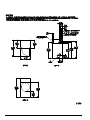
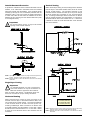
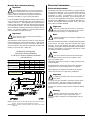
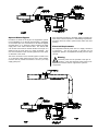
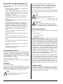
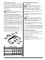
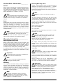
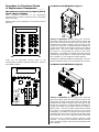
TYPICAL NATURAL GAS INSTALLATION
Before You Start
Check Local Codes and Permits
Call your local water company or the proper municipal
authority for information regarding local codes.
Important
!
It is your responsibility to have all plumbing
connections made by a qualified professional to
ensure that the plumbing installation is adequate and
conforms to local, state, and federal regulations or codes.
It is the installer’s or owner’s responsibility to see that the
required water pressure, pipe size, or connections are
provided. The manufacturer assumes no responsibility if
the fire suppression system is not connected, installed, or
maintained properly.
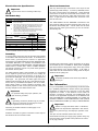
TYPICAL L.P. GAS INSTALLATION
Installation
Water Supply
The fire suppression system must be supplied with a
minimum water pipe size of 1/2-inch (12.7 mm) and be
provided with 40 psi +/- 20 psi (2.75 bar +/- 1.37 bar) of
pressure. For use of optional manual bypass, a second
source with the same piping and pressure requirements is
required.
If the rear area of the dryer or the water supply is located in an
area where it will be exposed to cold/freezing temperatures,
provisions must be made to protect these water lines from
freezing.
Consistent gas pressure is essential at all gas connections.
It is recommended that a 1-inch (2.54 cm) pipe gas loop be
installed in the supply line servicing a bank of dryers. An
in-line pressure regulator must be installed in the gas supply
line (header) if the (natural) gas pressure exceeds 12.0 in
WC (29.9 mb) pressure.
!
Note
A WC test pressure of 3.5 in WC (8.7 mb) for
natural gas and 10.5 in WC (26.1 mb) for L.P.
dryers is required at the gas valve pressure tap of each
dryer for proper and safe operation.
A 1/8” N.P.T. plugged tap, accessible for a test gauge
connection, must be installed in the main gas supply line
immediately upstream of each dryer.
Important
!
Pipe joint compounds that resist the action of
natural gas and L.P. gas must be used.
Test all connections for leaks by brushing on a soapy water
solution (liquid detergent works well).
!
Warning
Never test for leaks with a flame!!!
Warning
!
If the water in the supply line or water solenoid
valve freezes, the fire suppression system will be
inoperative!!
Water Connections
The water connection is made to the 3/4”-11.5 NH hose
adaptor, located in the upper right rear of the dryer. A flexible
supply line/coupling must be used in an effort to avoid
damaging the electric water solenoid valve.
!
Note
The 3/4”-11.5 NH is a standard hose coupling
screw thread. It is not to be confused with 3/4”
N.P.T. The sealing of an NH connection is made with a
washer opposed to the mating threads of an N.P.T.
assembly. The 2 thread designs are not compatible.
It is recommended that a filter or strainer be installed in the
water supply line.
!
Important
Flexible supply line/coupling must be used.
Solenoid valve failure due to hard plumbing
connections will void warranty.
The dryer is to be connected to the water mains using a
new hose set and the old hose set should not be reused.
14
American Dryer Corp.
113362-8