1
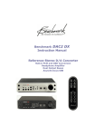
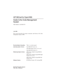
Benchmark ADC16
Instruction Manual
16-Channel 24-bit 192-kHz
Audio Analog-to-Digital Converter
Contents
Overview
3
Features
5
Front Panel
6
AC Power Switch
Clock Settings
Clock Status Indication
Source for Digital Outputs
Optical Output Format
Meter Display
Meter Scale and Peak Hold
Rear Panel
Analog Line-Level Inputs
Input Level Trim-Pots
AES Digital Audio I/O
Coaxial Digital Audio Outputs
Optical Digital Audio Outputs
Clock Reference Input
Word Clock Reference Output
Slot for Optional Interface Cards
AC Power Entry Connector
Fuse Holder
Specifications
Audio Performance
Group Delay (Latency)
Balanced Analog Audio Inputs
WC/SC/AES Clock Reference Input
AES Clock Reference Input
Balanced AES/EBU Digital Outputs
Coaxial Digital Outputs
Multi-Format Optical Digital Outputs
DAW Card Slot
Controls
Status Indicators
Meters
Power Requirements
Fuses
Dimensions
Weight
ADC16 Instruction Manual – Rev A
7
8
9
10
11
12
12
13
15
15
16
17
18
19
19
19
19
19
ADAT S/MUX Tutorial
26
Proper S/MUX Identification
ADAT S/MUX2 Flag
No S/MUX4 Flag
S/MUX Must be Decoded Before Digital
Processing
S/MUX Sample Rates Must Match
S/MUX Must Not be Used for SRC
26
26
26
26
27
27
UltraLockDDS™ … What Is It?
29
Regulatory Compliance
32
CE Certificate of Conformity
RoHS Compliance
32
33
Warranty Information
33
1 Year Warranty
Extended 5 Year Warranty - US and
Canada
Extended 2 Year International Warranty
Warranty Repair Procedure
Contact Information
33
33
34
34
35
20
20
21
22
22
22
23
23
23
23
24
24
24
24
24
25
25
Page 2
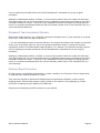
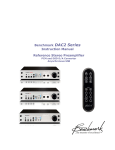
Overview
The ADC16 is a reference-quality, 16-channel,
192-kHz, 24-bit, analog-to-digital audio
converter.
The ADC16 utilizes Benchmark's
UltraLockDDS™ clock system with multifunction clock input and word clock output.
UltraLockDDS™ is a proprietary clock-sync
system that is immune to jitter.
UltraLockDDS™ is phase-accurate, even
across multiple ADC16 units.
The ADC16 has a wide variety of interfaces,
including AES/EBU, coaxial, ADAT, Toslink,
and more via an optional interface card. The
optical output supports AES or ADAT formats
at resolutions up to 192/24. In ADAT mode,
high sample rates are supported using
S/MUX2 and S/MUX4. The optional interface
card will enable direct connectivity to a
computer and other devices.
The signal-level meters on the ADC16 are
dual-range, 9-segment LEDs. The meters can
easily be switched to display a range of 48 dB
or 20 dB. The meters also have a peak-hold
function. The meters are single-sample
accurate for precise digital signal metering.
The ADC16 is designed for maximum
transparency. The ADC16 is well suited for
the most demanding applications in recording
and film studios. The internal power supply
supports all international voltages and has
generous margins for over and under voltage
conditions.
The ADC16 achieves outstanding performance
over a wide range of input levels. Each
channel has a 10-turn gain calibration
trimmer with a gain range of 23 dB. The gain
calibration controls may be used to calibrate
the ADC16 to precise studio reference levels.
The ADC16 has a BNC Word Clock output that
follows the sample rate indicated on the
front-panel display. Word Clock output is
active in all modes of operation.
ADC16 Instruction Manual – Rev A
A multi-format clock-input automatically
recognizes AES/EBU, SPDIF, Word Clock, or
Super Clock signals. This clock input is used
to synchronize the digital outputs. If desired,
the digital outputs may be clocked to the
ADC16's high-precision internal clock. The
ADC16 will automatically revert to the internal
clock source when the external clock is lost.
The ADC16 has four clock modes: 'DAW'
(optional interface card), 'AES' (DB-25
AES/EBU input), 'WC' (BNC), and 'INT'
(internal). All modes support sample rates
between 28 kHz and 200 kHz.
The 'DAW', 'AES', and 'WC' modes allow the
ADC16 to lock to an external clock reference.
In these modes, the ADC16 will follow
changes in sample rate. In 'WC' mode, the
ADC16 will also follow changes in the type of
reference signal (AES, SPDIF, word clock, or
super clock).
When the 'INT' mode is chosen, the ADC16 is
acting as clock master, operating at the
selected sample rate. In the 'INT' mode, any
signal at the clock-reference input will be
ignored. If 'INT' mode is used, all devices
connected to the ADC16 digital outputs will
need to be configured to lock to the ADC16.
Also, if the 'INT' mode is used, all other digital
sources (A/D converters, etc) connected to
the recording system must be synced to the
ADC16's clock. The 'WC' output and any of
the digital audio outputs on the back of the
ADC16 may be used as clock references to
feed connected devices.
The Benchmark UltraLockDDS™ clock-system
is highly immune to jitter. When synced to
the DAW, AES/EBU, WC, and super clock
interfaces, the A/D conversion-clock is
optimally conditioned using a technology
called Direct Digital Synthesis (DDS). The
UltraLockDDS™ system utilizes a
temperature-compensated crystal oscillator to
achieve an accurate center frequency
(important when the ADC16 is operating as a
master clock). The DDS system operates at
Page 3
500 MHz and includes digital filters to remove
jitter from the reference clock input. The
Benchmark UltraLockDDS™ clock-system
outperforms two-stage PLL designs while
providing the frequency agility to handle the
special sample rates that are often required
for video transfers to and from film.
The Benchmark UltraLockDDS™ system
delivers consistent performance under all
operating conditions. Users should not
hesitate to lock the ADC16 to other clock
sources. The UltraLockDDS™ will remove
jitter from the external clock reference, and
supply a clean clock to the internal A/D
converters.
The predecessor of UltraLockDDS™ is
UltraLock™, Benchmark's pioneering jitterelimination technology. UltraLockDDS™
meets or exceeds the performance of
Benchmark's UltraLock™ system, but does
not use asynchronous sample rate conversion
(ASRC). The elimination of the ASRC
processing reduces system latency and
provides the most direct path from the A/D to
the digital interface.
The ADC16 is designed to perform gracefully
in the presence of errors and interruptions at
the clock reference input. The ADC16 will
even lock to an AES/EBU signal that has its
sample-rate bit status set incorrectly since
the sample rate is determined by measuring
the incoming signal. Lack of sample-rate
status bits or incorrectly set status bits will
not cause loss of audio.
The ADC16 is phase-accurate between
channels and between other ADC16 boxes
when locked to AES/EBU or word clock
reference signals. The word clock output from
one ADC16 may be connected to the clock
input on another ADC16 to expand the
number of phase-accurate conversion
channels.
ADC16 Instruction Manual – Rev A
Page 4
Features
Sixteen (16) channels of 24-bit analog-to-digital audio conversion
9-segment dual-range digital LED meters with 'peak-hold' functionality
Multifunction clock input with auto-recognition of AES, SPDIF, Word Clock, or Super Clock
Capable of synchronizing to a master clock, other digital sources, and/or computer
Benchmark's phase-accurate jitter-immune UltraLockDDS™ technology
High-precision, low-jitter master clock via a temperature-compensated crystal oscillator
Word Clock output
Balanced analog inputs via two DB-25 connectors (eight channels per DB-25) - Tascam
pinout
+6 dBu to +29 dBu input sensitivity range (at 0 dBFS)
10-turn gain-calibration controls (1 per channel) with a 23 dB gain range
'Press-and-hold' buttons to prevent catastrophic incidents
Sample-rate selector and indicator for digital outputs
Conversion at sample rates between 28 and 200 kHz
Five types of digital output (AES/EBU, Coaxial, Toslink, ADAT, and optional interface card)
All digital outputs can be sourced from internal A/D or from optional interface card (DAW)
Optical output supports AES/EBU, ADAT, ADAT S/MUX2, and ADAT S/MUX4 output formats
THD+N = -104 dB, 0.00063% @ -3 dBFS input, SNR 121 dB A-weighted
Reliable and consistent performance under all operating conditions
Internal 90 - 264 VAC international power supply
Meets FCC Class B and CE emissions requirements
Tested to EN 6100-6-2 for RF immunity
ADC16 Instruction Manual – Rev A
Page 5
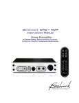
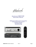
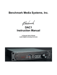
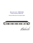
Front Panel
AC Power Switch - page 7
Clock Source - page 8
Settings: Internal Clock, Lock to WC / SC, Lock to AES, Lock to DAW Card
Clock Sample Rate - page 8
Settings: 44.1, 48, 88.2, 96, 176.4 and 192 kHz
Clock Status Indication - page 9
Lock Status, Reference Sample Rate, Error Reporting
Source for Digital Outputs - page 10
Settings: Source = Internal A/D Converters, Source = DAW Card
Optical Output Format - page 11
Settings: AES Format, ADAT Format, ADAT S/MUX2, ADAT S/MUX4
Meter Display - page 12
16 Dual-Range 9-Segment LED Meters, Driven from A/D Digital Outputs
Meter Scale and Peak Hold - page 12
Settings: Scale Factor = 1 dB/step or 6 dB/step, Peak-Hold On/Off
ADC16 Instruction Manual – Rev A
Page 6
AC Power Switch
DPDT (double-pole, double-throw) switch
disconnects both sides of the AC line. When
this switch is 'OFF', the ADC16 draws no
power. When this switch is turned 'ON', the
ADC16 will boot up and calibrate within 5
seconds.
User settings are automatically stored in
memory. These settings are automatically
recalled when power is restored.
ADC16 Instruction Manual – Rev A
Page 7
Clock Settings
WC – On = clock is locked to the WC
input via BNC
INT – On = clock reference is the
ADC16's internal clock
Clock Sample Rate
The 'SAMPLE RATE' control interface consists
of a 'SAMPLE RATE' button and LED display.
The 'CLOCK' control interface consists of a
'CLOCK SOURCE' button, a 'Sample Rate'
button. Each button has a corresponding LED
display.
The 'SAMPLE RATE' Button
The ADC16 can operate from its internal
clock, or it can lock to a variety of external
clock sources. Valid clock signals include
Word Clock, Super Clock, AES, SPDIF, and
the optional 'DAW' interface card.
Clock Source
'Clock Source' Button
The 'CLOCK SOURCE' button is a 'press-andhold' switch. This means that the user must
hold in the button for one second before the
clock source changes. The 'press-and-hold'
action prevents accidental changes.
The 'SAMPLE RATE' button sets the sample
rate when the ADC16 is in the 'INT' clocksource mode. This button is only active when
the 'INT' LED is on.
To change the internal clock sample rate,
press and hold the 'SAMPLE RATE' button.
The 'SAMPLE RATE' button must be held for 1
second to change to the next rate. The
'press-and-hold' action prevents accidental
changes.
'CLOCK SOURCE' LED Display
'SAMPLE RATE' LED Display
The 'CLOCK SOURCE' display indicates which
input is acting as a clock reference for the
ADC16. The indicators are as follows:
DAW – On = clock is locked to the
optional interface card
AES – On = clock is locked to the
AES/EBU input via DB-25
ADC16 Instruction Manual – Rev A
44.1kHz
48 kHz
88.2 kHz
96 kHz
176.4 kHz
192 kHz
The 'SAMPLE RATE' LED display always
indicates the sample rate at which the ADC16
is operating.
Page 8
In any external clock mode, the ADC16 will
automatically follow the sample rate of the
external reference signal. The measured
sample rate of the external source will be
displayed on the LEDs.
If the reference signal is good, the ADC16 will
lock within 8 seconds. The ADC16
UltraLockDDS™ system is very tolerant of
poor quality clock reference signals.
Clock Status Indication
Clock Error - Not Locked
'Clock Source' LED flashing rapidly
If selected clock source is present, the
corresponding clock source LED will flash
rapidly while the system is acquiring lock.
Allow up to eight seconds for the system to
lock. Failure to lock within 8 seconds is an
indication that the clock signal is corrupt or
invalid. After eight seconds, the clock system
will revert to internal sync, and the 'INT' LED
will turn on. The LED corresponding to the
selected sync source will continue to flash
once per second (indicating the "noreference" error condition).
Action: Check cables, connect a valid clock
signal, switch to a different clock source, or
switch the ADC16 to internal clock. Sample
rate of external clock must fall within one of
the following ranges: 28 – 50 kHz, 75-100
kHz, or 150 kHz-200 kHz
Clock Error - No Reference
'Clock Source' LED flashing once per
second, and "INT" LED ON
If no signal is present on the selected clock
input, the corresponding 'Clock Source' LED
will flash once per second, and the "INT' LED
will be on, indicating that the system has
reverted to internal sync.
Action: Check cables, connect a valid clock
signal, switch to a different clock source, or
switch the ADC16 to internal clock.
Clock Error - DAW Frequency
'Sample Rate' LEDs flashing once per
second
If the 'SAMPLE RATE' LED display is flashing,
this is an indication that the ADC16 and
optional DAW card are operating at different
frequencies. The DAW card is only functional
when the DAW sample rate matches that of
the ADC16.
Action: Change the sample rate of either the
DAW, the ADC16, or the external clock
reference. The ADC16 and DAW sample rates
must match.
Clock Error - DAW Clock Mode
'DAW' 'Clock Source' LED is flashing once
per second
If the DAW clock mode conflicts with the
ADC16 clock mode, the 'DAW' 'Clock Source'
LED will flash once per second. This can only
occur when the ADC16 is not using the DAW
as a clock source, or when the DAW card is
configured to lock to a source other than the
ADC16.
Action: Either change the ADC16 clock
source to 'DAW', or configure the DAW card
to use the ADC16 as a reference.
ADC16 Instruction Manual – Rev A
Page 9
Source for Digital Outputs
Routing A/D outputs through a
DAW and Back to Digital Outputs
The optional 'DAW' card provides a bidirectional 16-chanel interface between the
ADC16 and a DAW. Analog audio can be
converted in the ADC16, sent to the DAW,
mixed in the DAW and sent back out through
the ADC16 to external D/A converters.
Multiple mixes can be created for monitor
feeds or other uses.
The digital outputs can stream digital audio
data from either the ADC16's internal A/D
converters or from the source connected to
the optional 'DAW' interface card.
To select the source for a set of digital
outputs, press and hold the 'SOURCE' button
for that set of digital outputs ('AES OUT',
'SPDIF OUT', and 'OPTICAL OUT'). The
'SOURCE' button must be held for 1 second to
change. The 'press-and-hold' action prevents
accidental changes.
Routing A/D Conversion Directly
to Outputs
When 'A/D' is selected, the ADC16's internal
A/D converters are routed directly to the
digital outputs.
In any mode of operation, the A/D converter
outputs are also routed to the optional 'DAW'
card.
Using the ADC16 with an Analog
Summing Bus
The bi-directional 'DAW' interface card can be
used to send up to 16 channels of audio to
external D/A converters feeding an analog
summing bus. The outputs of the summing
bus can be connected to the analog inputs on
the ADC16 (and sent back to the DAW).
Using the ADC16 to Interface a
DAW with Analog Effects
The bi-directional 'DAW' interface card can be
used to send up to 16 channels of audio to
external D/A converters feeding analog
effects. The analog outputs of the effects can
be connected to the analog inputs on the
ADC16 (and sent back to the DAW).
Using the ADC16 as a Digital DAW
Interface
The optional DAW card provides a bidirectional 16-channel interface to an external
device such as a digital audio workstation
(DAW). The 16-channel return path from the
DAW can be routed to external D/A
converters using any of the digital audio
outputs on the ADC16. In such a system, it
is not necessary to purchase a DAW interface
for the D/A converters. The ADC16 provides
the interface between the DAW and the
external D/A converters.
ADC16 Instruction Manual – Rev A
Page 10
Optical Output Format
The optical output can provide either
AES/EBU or ADAT format. The AES/EBU
mode works with most S/PDIF optical inputs.
Press and hold the 'FORMAT' button to change
the optical output format. The 'press-andhold' action prevents accidental changes.
When ADAT is active, S/MUX is automatically
enabled at all 2X and 4X sample rates (88.2
kHz, 96 kHz, 176.4 kHz, and 192 kHz).
ADC16 Instruction Manual – Rev A
Page 11
Meter Display
The ADC16 is equipped with a multi-function
9-segment LED meter. The 'SCALE' button
selects either a 6 dB step or 1 dB step scale
and controls the peak-hold function. Metering
is fully digital and post-conversion for
absolute accuracy. The units are dBFS (dB
relative to the maximum possible digital
signal).
Time constants are built into the meters so all
transient peaks can be observed easily. If a
transient peak has a duration as short as one
digital sample, an LED will be illuminated and
remain illuminated long enough to be
observed by the human eye.
A peak indication mimics the action of the
needle on a peak-reading analog meter, while
the remaining LEDs will follow the
instantaneous level of the audio.
The red 0 LED indicates that a full-scale
digital code has been reached and that digital
clipping has occurred. Full-scale events as
ADC16 Instruction Manual – Rev A
short as one digital sample will light the 0
LED. Short single-sample digital clipping
events are often audible, and all 0-dBFS
events should be avoided.
The ADC16 has a very large dynamic range.
It is wise to use some of this dynamic range
to provide more headroom as insurance
against clipping. Leave some extra headroom
between your highest anticipated peak and
the red 0 dBFS LED.
Meter Scale and Peak Hold
The 'SCALE' button selects the scale and
peak-hold mode of the 9-segment LED Meter
Display.
Meter Scale and Peak Hold
Function Selection
Press the 'SCALE' button momentarily to
enable or disable the Peak Hold function.
Press and hold the 'SCALE' button to switch
the scale between 1 dB steps and 6 dB steps.
Page 12
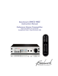
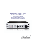
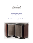
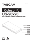
Rear Panel
Analog Line-Level Inputs - page 15
Tascam Analog DB-25 Standard Pinout - 2 Connectors - 16 Channels In
Input Level Trim-Pots - page 15
One 10-Turn Trimmer per Channel, 23 dB Adjustment Range, Preset for +4 dBu @ -20 dBFS
AES Digital Audio I/O - page 16
Tascam AES/EBU DB-25 Standard Pinout - 2 Connectors - 16 Channels Out - 2 Channels In
Coaxial Digital Audio Outputs page 17
AES Professional Format 1Vpp Coaxial Outputs - 16 Channels Out
Optical Digital Audio Outputs - page 18
8 Optical Output Connectors - Supporting AES, ADAT, S/MUX2, and S/Mux4
Clock Reference Input - page 19
75-Ω BNC Input - Accepts Word Clock, Super Clock, and AES Input - Auto Recognizing
Word Clock Reference Output - page 19
75-Ω BNC Output - 2.5 Vpp into 75-Ω Load, DC Coupled
ADC16 Instruction Manual – Rev A
Page 13
Slot for Optional Interface Cards - page 19
See http://www.BenchmarkMedia.com/ADC16/optional-interface-card
AC Power Entry Connector - page 19
IEC Power Connector
Fuse Holder - page 19
Requires two 0.5 Amp 5 x 20 mm 250 V Slo-Blo® Type fuses
ADC16 Instruction Manual – Rev A
Page 14
Analog Line-Level Inputs
Unbalanced Source Adaptation
1. Connect "+" or hot (tip on ¼ phone plug,
center pin on RCA plug).
2. Connect both the ground conductor AND
the"-" conductor to the connector's
ground (sleeve on ¼" phone plug, or case
on RCA plug).
The balanced "ANALOG IN" line-level inputs
follow the Tascam Analog DB-25 standard.
Cables are available from many sources.
NOTE: When connecting an unbalanced
source to the balanced analog input, it's best
to use balanced wiring ("+", "-", "shield") and
to tie the "-"and "shield" at the unbalanced
connector (source).
Input Level Trim-Pots
The analog inputs are factory calibrated to an
input sensitivity of +4 dBu @ -20 dBFS. Rearpanel trim pots ( ) allow adjustment over a
23-db range. At minimum gain, the
sensitivity is +9 dBu at -20 dBFS. At
maximum gain, the sensitivity is -14 dBu at 20 dBFS. Unbalanced -10 dBv inputs are
easily accommodated within this range.
The input impedance is 200k Ohms balanced,
and 100k Ohms unbalanced.
Each analog input is equipped with an RF
filter network. The ADC16 exhibits no
measurable change in performance when
subjected to EN 61000-6-2 RF immunity
tests.
Each channel on the ADC16 is equipped with
10-turn "INPUT LEVEL" trim-pots. These trim
pots are located on the back panel near the
optical outputs.
The "INPUT LEVEL" trim-pots have a range of
approximately 23 dB. At their minimum
setting, the ADC16 will clip upon receiving a
+29 dBu analog input signal. At their
maximum setting, the ADC16 will clip upon
receiving a +6 dBu analog input signal.
The "INPUT LEVEL" trim-pots are factory-set
to clip at +24 dBu.
'ANALOG IN' DB-25 Pinout
The 'ANALOG IN' DB-25 pinout follows the
Tascam Analog DB-25 standard:
H = "+" (or hot), C = "-" (or cold), G = GND
ADC16 Instruction Manual – Rev A
Page 15
AES Digital Audio I/O
The balanced 'AES I/O' digital I/O connectors
follow the Tascam AES/EBU DB-25 standard.
Cables are available from many sources.
These 110-Ω 'AES I/O' connections include
DC-isolation, transformer-coupling, currentlimiting, and diode-protection. Outputs are
designed to drive standard 4 Vpp AES signals
into a 110-Ω load. 110-Ω digital cables are
required when connecting these signals to
other devices. Analog audio cables may
cause data transmission errors, and should
not be used to transmit digital audio.
Data Format = AES/EBU professional
Word Length = 24 bits
Sample Rate = 28 to 50 kHz, 75 to
100 kHz, and 150 kHz to 200 kHz
Clock Source = Internal or External
Data Source = A/D or DAW
The digital audio data at the ADC16's digital
outputs can come from one of two sources:
the ADC16's A/D converters ('A/D') or the
optional interface card ('DAW').
'AES I/O' DB-25 Pinout
The 'AES I/O' DB-25 pinout follows the
Tascam AES/EBU DB-25 standard:
H = "+" (or hot), C = "-" (or cold), G = GND
The Tascam AES/EBU DB-25 standard
provides four 2-channel inputs and four 2channel outputs for a total of 8 channels in
and 8 channels out (on each DB-25
connector). For example, 'Digital Out' '1'
carries channels 1 and 2, and 'Digital Out' '2'
carries channels 3 and 4.
The ADC16 uses all 4 of the digital outputs on
each DB-25 connector (for a total of 16 audio
channels on 8 digital outputs).
The ADC16 only uses one of the 8 available
digital inputs. Digital input 1 on the top DB25 connector (audio channels 1 and 2) can be
used as a clock reference input. The ADC16
can lock to an AES digital audio signal on this
input when 'Clock Source' is set to 'AES'.
All digital inputs (including the unused
inputs), are terminated with 110 Ω. 'Digital
In' '2', '3', and '4' are unused on the top DB25 connector. 'Digital In' '1', '2', '3', and '4'
are unused on the bottom DB15 connector.
The user can select digital output sources via
the 'SOURCE' buttons on the front panel.
Each set of outputs ( 'AES I/O', 'S/PDIF', and
'Optical') has a 'SOURCE' selection button.
These may be used in any combination.
When DAW is selected as the source, the user
can assign any tracks or sub-mixes of tracks
to the AES outputs.
ADC16 Instruction Manual – Rev A
Page 16
Coaxial Digital Audio Outputs
The ADC16 features eight coaxial digital
outputs. There is one RCA coaxial connector
for each pair of digital-audio output channels.
The coaxial outputs are designed to operate
within AES3-id and SMPTE 276M standards,
and drive 1Vpp into 75-Ω. 75-Ω coaxial
cables are required when connecting these
outputs to other devices. Data transmission
errors may occur if the wrong cables are
used.
The digital audio data at the ADC16's digital
outputs can come from one of two sources:
the ADC16's A/D converters ('A/D') or the
optional interface card ('DAW')
The user can select digital output sources via
the 'SOURCE' buttons on the front panel.
Each set of outputs ( 'AES I/O', 'S/PDIF', and
'Optical') has a 'SOURCE' selection button.
These may be used in any combination.
When 'DAW' is selected as the source, the
user can assign any tracks or sub-mixes of
tracks to the coaxial outputs.
The coaxial outputs on the ADC16 are DCisolated, transformer-coupled, currentlimited, and diode-protected. They
incorporate filtering to minimize RF
interference and susceptibility.
Data Format = AES/EBU professional
Word Length = 24 bits
Sample Rate = 28 to 50 kHz, 75 to
100 kHz, and 150 kHz to 200 kHz
Clock Source = Internal or External
Data Source = A/D or DAW
ADC16 Instruction Manual – Rev A
Page 17
Optical Digital Audio Outputs
The ADC16 features eight optical digital
outputs. These outputs can be operated in
four different modes: 'S/PDIF', 'ADAT', 'ADAT
S/MUX2', and 'ADAT S/MUX4'. The 'FORMAT'
button on the front panel toggles between
'S/PDIF' and 'ADAT' formats. If any ADAT
mode is selected, S/MUX2, or S/MUX4 will be
enabled automatically depending upon the
system sample rate.
In 'S/PDIF' mode, each optical connector
carries two audio channels. Data format is
AES professional. The optical transmitters on
the ADC16 support a maximum sample rate
of 200 kHz in 'S/PDIF' mode . However, most
optical inputs do not support S/PDIF or AES
formats at high sample rates. Check the
specifications on connected equipment before
relying on high sample-rate optical
connections.
In 'ADAT' mode, each optical carries eight
channels of digital audio. In this mode, two
optical connectors are required to carry all 16
channels produced by the ADC16. The
remaining 6 optical connectors provide two
additional sets of outputs. 'ADAT' mode is
only available at sample rates between 28
and 50 kHz. If a higher sample rate is
selected, 'S/MUX2' or 'S/MUX4' is
automatically enabled.
ADAT 'S/MUX2' is available at sample rates
between 75 and 100 kHz. In this mode, each
optical output carries four channels of audio.
Four connectors are required for 16 channels
of audio. The 8 optical connectors on the
ADC16 carry two identical sets of data when
operating in ADAT 'S/MUX2'.
The optical outputs use what is often called a
TOSLINK, Type FO5, or 5 mm optical
connector. The ADC16 uses a special highbandwidth version that supports AES/EBU
digital audio at sample rates up to 192 kHz.
Please note that many optical inputs cannot
support AES/EBU or SPDIF digital audio at
sample rates above 48 kHz. Some others are
limited to 96 kHz. A few products (such as the
Benchmark DAC1) support 192 kHz optical
inputs. Please note that high-bandwidth
optical transmitters and receivers are not
required for ADAT, ADAT S/MUX2, or even
ADAT S/MUX4.
AES/EBU 'S/PDIF' Optical Mode
Data Format = AES/EBU professional
Word Length = 24 bits
Sample Rates = 28 - 50 kHz, 75 - 100
kHz, and 150 - 200 kHz
Clock Source = Internal or External
Data Source = A/D or DAW
ADAT Optical Output Mode
Data Format = ADAT
Word Length = 24 bits
Sample Rates = 28 to 50 kHz
Clock Source = Internal or External
Data Source = A/D or DAW
ADAT S/MUX2 Optical Output
Mode
Data Format = ADAT
Word Length = 24 bits
Sample Rate = 75 to 100 kHz
Clock Source = Internal or External
Data Source = A/D or DAW
ADAT S/MUX4 Optical Output
Mode
Data Format = ADAT
Word Length = 24 bits
Sample Rate = 150 to 200 kHz
Clock Source = Internal or External
Data Source = A/D or DAW
ADAT 'S/MUX4' is available at sample rates
between 150 and 200 kHz. In this mode,
each optical output carries two channels of
digital audio. All 8 optical connectors are
required, to carry 16-channels of audio.
ADC16 Instruction Manual – Rev A
Page 18
Clock Reference Input
Slot for Optional Interface Cards
An interface card can be installed in the
ADC16. The card is installed in the slot to the
left of the AC power input. This slot provides
a bi-directional 16-channel interface to
external devices such as a digital audio
workstation (DAW).
The Clock Reference Input uses a BNC
connector and is terminated with 75 Ohms.
This input is DC isolated and includes
overvoltage protection. This input autodetects AES/EBU, SPDIF, Word Clock, or 256X
Super Clock signals. When 'WC' mode is
active the ADC16 will lock to this external
clock input, and automatically follow changes
in sample-rate.
Benchmark's UltraLockDDS™ circuitry isolates
the conversion clock from any jitter present
on the clock reference. 'WC' mode will not
degrade the conversion quality of the ADC16,
even when very high levels of jitter are
present on the clock reference.
Word Clock Reference Output
For more information, go to
http://www.BenchmarkMedia.com/ADC16/opt
ional-interface-card
AC Power Entry Connector
The AC power input uses a standard IEC type
connector. Within the USA and Canada, the
ADC16 ships with a power cord. In other
locations, a location-specific IEC style power
cord may be purchased from a local source
(including a local Benchmark dealer).
Fuse Holder
The fuse holder is built into a drawer next to
the IEC power connector. The drawer
requires (two 5 x 20 mm 250 V Slo-Blo®
Type) fuses. The fuse rating (for all voltage
settings is 0.50 Amps).
Caution: Always install the correct fuses.
The Word Clock output provides a clock signal
which can be used to synchronize
downstream components.
When the ADC16 is running in 'INT' mode
(internal clock mode), the clock frequency at
this output has an initial accuracy of +/- 5
PPM with a +/- 1PPM/yr aging characteristic.
The INT mode is suitable as a studio master
clock.
ADC16 Instruction Manual – Rev A
The mains power input has a very wide
operating range. The ADC16 power supply
can operate over an AC frequency range of 47
to 440 Hz, within a voltage range of 90 to 264
VAC. It can also operate from DC voltages
between 127 and 300 VDC. There are no
settings to change.
Page 19
Specifications
Audio Performance
Fs = 44.1 to 192 kHz, 20 to 20 kHz BW, 1 kHz test tone, 0 dBFS = +24 dBu (unless noted)
SNR – A-Weighted, 0 dBFS = +16 to +29 dBu
121 dB
SNR – Unweighted, 0 dBFS = +16 to +29 dBu
119 dB
SNR – A-Weighted at max gain, 0 dBFS = -10 dBv
117 dB
THD+N, 1 kHz at –1 dBFS
-102 dBFS, -101 dB, 0.00089%
THD+N, 1 kHz at –3 dBFS
-107 dBFS, -104 dB, 0.00063%
THD+N, 20 to 20 kHz test tone at –3 dBFS
-105 dBFS, -102 dB, 0.00079%
Frequency Response at Fs=192 kHz
-3 dB, +0 dB, 2 Hz to 94 kHz
+/- 0.02 dB, 20 Hz to 20 kHz
-0.06 dB at 10 Hz
-0.01 dB at 20 Hz
+0.02 dB at 20 kHz
-0.35 dB at 88 kHz
-3 dB at 94.6 kHz
-117 dB at 108 kHz
Frequency Response at Fs=96 kHz
-3 dB, +0 dB,1 Hz to 47 kHz
+/- 0.01 dB, 20 Hz to 20 kHz
-0.06 dB at 10 Hz
-0.01 dB at 20 Hz
+0.02 dB at 20 kHz
-0.10 dB at 44 kHz
-3 dB at 47.3 kHz
-115 dB at 54 kHz
Frequency Response at Fs=48 kHz
-3 dB, +0 dB, 1 Hz to 23.6 kHz
+/- 0.01 dB, 20 Hz to 20 kHz
-0.06 dB at 10 Hz
-0.01 dB at 20 Hz
+0.02 dB at 20 kHz
-0.10 dB at 22 kHz
-3 dB at 23.6 kHz,
-110 dB at 27 kHz
Passband Ripple
+/- 0.001 dB at 44.1 and 48 kHz
+/- 0.003 dB at 88.2 and 96 kHz
+/- 0.007 dB at 176.4 and 192 kHz
Crosstalk
-96 dB at 20 kHz
-120 dB at 1 kHz
< -135 dB at 20 Hz
Jitter Tolerance (With no Measurable Change in THD+N
>12.75 UI sine, 100 Hz to 10 kHz
Performance)
> 3.5 UI sine at 20 kHz
> 1.2 UI sine at 40 kHz
> 0.4 UI sine at 80 kHz
> 0.29 UI sine at 90 kHz
> 0.25 UI sine above 160 kHz
Maximum Amplitude of Jitter-Induced Sidebands
< -116 dB (10 kHz 0 dBFS test tone,
12.75 UI sinusoidal jitter at 1 kHz)
Maximum Amplitude of Spurious Tones with 0 dBFS test
-130 dBFS
signal
Maximum Amplitude of Idle Tones
-130 dBFS
ADC16 Instruction Manual
Page 20
Maximum Amplitude of AC line related Hum & Noise
Interchannel Differential Phase (Stereo Pair)
Interchannel Differential Phase (Between ADC16 Units)
Maximum Lock Time after Fs change
Mute on Sample Rate Change
Mute on Loss of External Clock
Mute on Lock Error
-140 dBFS
+/- 0.25 degrees at 20 kHz
+/- 0.25 degrees at 20 kHz
< 8 seconds
Yes - less than 8 seconds duration
Yes - after 5 seconds of no clock
Yes - after 5 seconds of no lock
Group Delay (Latency)
Delay (Analog Input to Digital Output)
ADC16 Instruction Manual
1.49
1.37
0.75
0.68
0.37
0.34
ms
ms
ms
ms
ms
ms
at
at
at
at
at
at
44.1 kHz
48 kHz
88.2 kHz
96 kHz
176.4 kHz
192 kHz
Page 21
Balanced Analog Audio Inputs
Number of Inputs
Connectors
Connector Pinout
Impedance
Sensitivity at Maximum Gain
Sensitivity at Factory Preset Gain
Sensitivity at Minimum Gain
Maximum Input Level at Maximum Gain
Maximum Input Level at Factory Preset Gain
Maximum Input Level at Minimum Gain
CMRR
Common Mode Trim
16
Two 25-pin DB-25 Connectors
Tascam Analog DB-25 Standard
200 kΩ Balanced, 100 kΩ Unbalanced
-14 dBu @ -20 dBFS
+4 dBu @ -20 dBFS
+9 dBu @ -20 dBFS
+6 dBu @ 0 dBFS
+24 dBu @ 0 dBFS
+29 dBu @ 0 dBFS
> 90 dB @ 1 kHz
Dual Frequency
RF Filter
Transient Protection
Over-Voltage Protection
AC Coupled
WC/SC/AES Clock Reference Input
Connector
Input Impedance
Input Formats (Auto Detected)
Sensitivity with Word Clock Input
Sensitivity with Super Clock Input
Sensitivity with AES Input
BNC
75 Ω
Word Clock, 256X Super Clock, AES
320 mVpp
500 mVpp
150 mVpp
RF Filter
Transient Protection
Over-Voltage Protection
AC Coupled
UltraLockDDS™ Jitter Attenuation
AES Clock Reference Input
Connector
Connector Pinout
Input Impedance
Input Formats
Sensitivity
ADC16 Instruction Manual
Uses 'Digital In 1' on Top AES DB-25
Tascam AES DB-25
110-Ω Balanced
AES, S/PDIF - Pro. or Consumer
150 mVpp
RF Filter
Transient Protection
Over-Voltage Protection
Transformer Coupled
DC Blocking Capacitor
UltraLockDDS™ Jitter Attenuation
Page 22
Balanced AES/EBU Digital Outputs
Audio Channels
Output Format
Output Sample Rate
Output Word Length
Connectors
Connector Pinout
Output Impedance
Output Level
16
AES3 Professional Data Format
Up to 200 kHz
24-bits
Two DB-25 Connectors
Tascam AES DB-25 Pinout
110-Ω
4 Vpp into 110 Ω
Transformer Coupled
DC Blocking Capacitors
Transient Protection
Over-Voltage Protection
RF Filters
Coaxial Digital Outputs
Audio Channels
Output Format
Output Sample Rate
Output Word Length
Connectors
Output Impedance
Output Level
16
AES3 Professional Data Format
Up to 200 kHz
24-bits
Eight RCA Connectors
75-Ω
1 Vpp into 75 Ω
Transformer Coupled
DC Blocking Capacitors
Transient Protection
Over-Voltage Protection
Maximum Sample Rate 200 kHz
RF Filters
Multi-Format Optical Digital Outputs
Audio Channels
Output Formats
Output Sample Rate
Output Word Length
Connectors
16
AES3, ADAT, ADAT S/MUX2, and
ADAT S/MUX4
Up to 200 kHz
24-bits
Eight Toslink Optical Transmitters
DAW Card Slot
Audio Channels
Sample Rates
Output Word Length
External Interfaces
ADC16 Instruction Manual
16 In and 16 Out
Up to 200 kHz (Card Dependent)
24-bits
Card Dependent
Page 23
Controls
Power Switch
Clock Source
Sample Rate
AES Output Source
Coaxial Output Source
Optical Output Source
Optical Format
Meter Range (Uses Meter 'SCALE' Button)
Meter Peak Hold (Uses Meter 'SCALE' Button)
Rocker
Button With
Button With
Button With
Button With
Button With
Button With
Button With
Button With
Delayed Response
Delayed Response
Delayed Response
Delayed Response
Delayed Response
Delayed Response
Delayed Response
Instant Response
*
*
*
*
*
*
**
* Delayed response (push and hold) prevents accidental changes to these session-critical settings.
** Delayed response (push and hold) allows shared use of the meter 'SCALE' button.
Status Indicators
Clock Source
Sample Rate
AES Output Source
Coaxial Output Source
Optical Output Source
Optical Format
Meter Range
Meter Peak Hold
INT, WC, AES, DAW
44.1, 48, 2X, 4X
A/D, DAW
A/D, DAW
A/D, DAW
AES, ADAT, SMUX2, SMUX4
1 dB, 6 dB
Peak Hold On
Meters
Number of Channels
Number of LED Segments per Channel
Total Number of LED Segments
Ranges
Peak Response Time
Ballistics
Peak Hold Function
16
9
144
2 (1dB/step, and 6dB/step)
1 sample
Fast Attack, Slow Decay
Yes, Both Ranges
Power Requirements
Mains Voltage
Frequency
Inrush Current
Power
Power Factor
90 - 264 VAC, or 127 - 300 VDC
47 - 440 Hz, or DC
< 60 A Peak @ 230 VAC
45 W Maximum, 40 W Typical
0.7
Fuses
Type
Quantity
ADC16 Instruction Manual
5 x 20 mm 0.5 A 250 V Slo-Blo®
2 Required
Page 24
Dimensions
Form Factor
Depth Behind Front Panel
Recommended Minimum Rack Depth to Clear Cables
Depth
Width
Height
1 Rack Wide, 1 RU High 12.125"
16"
12.5"
19"
1.725"
Weight
ADC16 only
Shipping Weight
ADC16 Instruction Manual
7.0 lbs.
10 to 12 lbs.
Page 25
ADAT S/MUX Tutorial
Proper S/MUX Identification
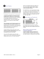
S/MUX2 allows the recording of 4 channels at 88.2 or 96 kHz using a standard 8-channel 44.1 or 48
kHz ADAT recorder. S/MUX4 allows the recording of 2 channels at 176.4 or 192 kHz using a
standard 8-channel 44.1 or 48 kHz ADAT recorder. In either case it is important to identify S/MUX
recordings so that they can be properly decoded upon playback. Failure to properly decode an
S/MUX recording will add unwanted artifacts to the audio. The severity of these artifacts is a
function of the high-frequency content of the original digital audio signal, and may range from
inaudible to very objectionable. This variation in severity can make it difficult to accurately spot a
problem just by listening to a portion of the recording.
An ADAT S/MUX2 recording will have pairs of nearly identical tracks (1≈2, 3≈4, 5≈6, and 7≈8).
Unfortunately this can be mistaken for 4 stereo pairs at half of the original sample rate. There is no
substitute for proper labeling. This labeling should include the sample rate of the recording.
An ADAT S/MUX4 recording is somewhat easier to identify because it will have groups of 4 channels
that are nearly identical (1≈2≈3≈4, and 5≈6≈7≈8). In error, S/MUX 4 could be played at ¼ of its
original sample rate, and sound almost normal. S/MUX 4 could also be mistaken for S/MUX2 and
could be played at ½ of its original sample rate. Please note that these changes in sample rate will
not alter the pitch of the audio but will introduce errors, and these errors may not be discovered
until it's too late to correct them.
ADAT S/MUX2 Flag
The ADAT specification was amended in February of 2001 to include an S/MUX2 flag. The ADAT
Interface carries 4 'user bits' per frame, and user bit U2 is now designated as an S/MUX2 flag. U2
should be set high when the interface is carrying S/MUX2. The ADC16 follows this standard.
Unfortunately, many devices ignore the user bits, and therefore, these devices will not respond to
the S/MUX2 flag. Again, the user must use caution when using an S/MUX connection.
No S/MUX4 Flag
The February 2001 addendum to the ADAT specification made no provisions for an S/MUX 4 flag.
User bit U2 should not be set in S/MUX4 applications. Unfortunately, this means that the S/MUX4
user bit configuration is identical to normal ADAT usage. Consequently, at the current time, user
bits cannot be used to indicate S/MUX4. This could change in the future. Again, the user must use
caution when using an S/MUX connection.
S/MUX Must be Decoded Before Digital Processing
No DSP process should be applied to an S/MUX signal before it is decoded. S/MUX must be
decoded before it reaches the internal processing in a DAW or a digital console. Many such devices
include S/MUX decoders at their digital interfaces and these decoders must be properly enabled for
S/MUX and disabled for standard ADAT inputs.
ADC16 Instruction Manual
Page 26
S/MUX Sample Rates Must Match
Most devices (including the ADC16) automatically enable and disable S/MUX in response to
changes in sample rate. Therefore it is essential that all S/MUX equipped A/D converters, D/A
converters, digital consoles, digital audio workstations, and digital processing devices be set to
identical sample rates. There is one exception to this rule: A non-S/MUX ADAT recorder can be
connected to an S/MUX interface, but the recorder must be set to ½ the audio sample rate if
S/MUX2 is in use, or ¼ the audio sample rate if S/MUX4 is in use.
S/MUX Must Not be Used for SRC
If two devices are connected with an ADAT S/MUX interface and the devices are set to different
sample rates, a crude form of SRC (sample rate conversion) will occur. For example, if an A/D
converter is set to 96 kHz, and it feeds a digital console that is set to 48 kHz, the system will
appear to down convert from 96 kHz to 48 kHz. This would be a useful feature if the digital filtering
was correct. The problem is that this ad-hoc sample rate converter is lacking the low-pass filter
that prevents aliasing.
ADC16 Instruction Manual
Page 27
ADAT S/MUX2 Channel Assignments*
ADAT
ADAT
ADAT
ADAT
ADAT
ADAT
ADAT
ADAT
Channel
Channel
Channel
Channel
Channel
Channel
Channel
Channel
1
2
3
4
5
6
7
8
=
=
=
=
=
=
=
=
Audio
Audio
Audio
Audio
Audio
Audio
Audio
Audio
Channel
Channel
Channel
Channel
Channel
Channel
Channel
Channel
1.a
1.b
2.a
2.b
3.a
3.b
4.a
4.b
* 'X.a' and 'X.b' are successive samples of audio channel X
ADAT S/MUX4 Channel Assignments**
ADAT
ADAT
ADAT
ADAT
ADAT
ADAT
ADAT
ADAT
Channel
Channel
Channel
Channel
Channel
Channel
Channel
Channel
1
2
3
4
5
6
7
8
=
=
=
=
=
=
=
=
Audio
Audio
Audio
Audio
Audio
Audio
Audio
Audio
Channel
Channel
Channel
Channel
Channel
Channel
Channel
Channel
1.a
1.b
1.c
1.d
2.a
2.b
2.c
2.d
** 'X.a', 'X.b' 'X.c' and 'X.d' are successive samples of audio channel X
ADC16 Instruction Manual
Page 28
UltraLockDDS™ … What Is It?
Accurate audio conversion requires a very low-jitter conversion clock. Jitter can easily cause severe
inaccuracies if not adequately addressed, even when the device employs high-performance
converter chips.
UltraLockDDS™ is Benchmark's latest jitter-immune clock technology. The ADC16 is the first
device to employ Benchmark's new UltraLockDDS™ technology to eliminate all jitter-induced
performance problems.
Benchmark's new UltraLockDDS™ clock system utilizes the latest low-jitter clock technology
developed for high-frequency RF communications systems. The master oscillator is a low phasenoise, temperature-compensated, fixed-frequency crystal oscillator with a +/- 2 PPM frequency
accuracy. This oscillator drives a 500 MHz Direct Digital Synthesis (DDS) system that generates a
3072 x WC system clock. This high-frequency clock is divided by 6 and distributed directly to the
A/D converters using a high-speed PECL clock distribution chip. Each of the 8 converters are driven
directly from a dedicated, matched-impedance transmission line.
Jitter attenuation is achieved with digital filters in a custom FPGA that controls the DDS system. All
jitter-induced distortion artifacts are well below audibility under all operating conditions. Jitterinduced distortion is always at least 135 dB below the level of the music. The jitter-performance of
UltralLockDDS™ meets or exceeds the performance of Benchmark's UltraLock™ system, but does
not use asynchronous sample rate conversion (ASRC). The elimination of the ASRC processing
significantly reduces system latency and provides the most direct path from the A/D to the digital
interface.
Does my system have a jitter problem?
Jitter is present on every digital audio interface. This type of jitter is known as interface jitter and it
is present even in the most carefully designed audio systems. Interface jitter accumulates as digital
signals travel down a cable and from one digital device to the next. If we measure interface jitter in
a typical system we will find that it is 10 to 10,000 times higher than the level required for
accurate 24-bit conversion. However, this interface jitter has absolutely no effect on the audio
unless it influences the conversion clock in an analog-to-digital converter (ADC) or in a digital-toanalog converter (DAC).
Many converters use a single-stage Phase Lock Loop (PLL) circuit to derive their conversion clocks
from AES/EBU, Word Clock, or Super Clock reference signals. Single-stage PLL circuits provide
some jitter attenuation above 5 kHz but none below 5 kHz. Unfortunately, digital audio signals
often have their strongest jitter components at 2 kHz. Consequently, these converters can achieve
their rated performance only when driven from very low jitter sources and through very short
cables. It is highly unlikely that any converter with a single-stage PLL can achieve better than 16
bits of performance in a typical installation. Actual performance may be severely degraded below
specified performance in most installations.
Better converters usually use a two-stage PLL circuit to filter out more of the interface jitter. In
theory, a two-stage PLL can remove enough of the jitter to achieve accurate 24-bit conversion (and
some do). However, not all two-stage PLL circuits are created equal. Many two-stage PLLs do not
remove enough of the low-frequency jitter. In addition, two-stage PLL circuits often require many
ADC16 Instruction Manual
Page 29
seconds to lock to an incoming signal, and may have a very limited frequency range. Two-stage
PLLs may fail to lock if the reference signal is slightly off frequency. Two-stage PLLs may also fail
to lock when jitter is too high.
UltraLockDDS™ converters exceed the jitter performance of two-stage PLL converters, and are free
from the slow-lock and no-lock problems that can plague two-stage PLL designs. UltraLockDDS™
converters are highly immune to interface jitter under all operating conditions.
UltraLockDDS™ isolates the conversion clock from the digital audio interface clock. Jitter on the
reference input can never have any significant effect on the conversion clock of an UltraLockDDS™
converter. Interface jitter cannot degrade the quality of the audio conversion in an UltraLockDDS™
converter. Specified performance is consistent and repeatable in any installation!
How does conversion clock jitter degrade converter performance?
Problem #1
Jitter phase modulates the audio signal. This modulation creates sidebands (unwanted tones)
above and below every tone in the audio signal. Worse yet, these sidebands are often widely
separated from the tones in the original signal.
Jitter-induced sidebands are not musical in nature because they are not harmonically related to the
original audio. Furthermore, these sidebands are poorly masked (easy to hear) because they can
be widely separated above and below the frequencies of the original audio tones. In many ways,
jitter induced distortion resembles intermodulation distortion (IMD). Like IMD, jitter induced
distortion is much more audible than harmonic distortion, and more audible than THD
measurements would suggest.
Jitter creates new audio that is not harmonically related to the original audio signal. This new audio
is unexpected and unwanted. It can cause a loss of imaging, and can add a low and mid frequency
"muddiness" that was not in the original audio.
Jitter induced sidebands can be measured using an FFT analyzer.
Problem #2
Jitter can severely degrade the anti-alias filters in an over-sampling converter. This is a little known
but easily measurable effect. Most audio converters operate at high over-sampling ratios. This
allows the use of high-performance digital anti-alias filters in place of the relatively poor performing
analog anti-alias filters. In theory, digital anti-alias filters can have extremely sharp cutoff
characteristics, and very few negative effects on the in-band audio signal. Digital anti-alias filters
are usually designed to achieve at least 100 dB of stop-band attenuation. But, digital filters are
designed using the mathematical assumption that the time interval between samples is a constant.
Unfortunately, sample clock jitter in an ADC or DAC varies the effective time interval between
samples. This variation alters the performance of these carefully designed filters. Small amounts of
jitter can severely degrade stop-band performance, and can render these filters useless for
preventing aliasing.
The obvious function of a digital anti-alias filter is the removal of audio tones that are too high in
frequency to be represented at the selected sample rate. The not-so-obvious function is the
removal of high-frequency signals that originate inside the converter box, or even originate inside
ADC16 Instruction Manual
Page 30
the converter IC. These high-frequency signals are a result of crosstalk between digital and analog
signals, and may have high amplitudes in a poorly designed system. Under ideal (low jitter)
conditions, a digital anti-alias filter may remove most of this unwanted noise before it can alias
down into lower (audio) frequencies. These crosstalk problems may not become obvious until jitter
is present.
Stop-band attenuation can be measured very easily by sweeping a test tone between 24 kHz and
at least 200 kHz while monitoring the output of the converter.
Put UltraLockDDS™ converters to the test
We encourage our customers to perform the above tests on UltraLockDDS™ converters (or let your
ears be the judge). There will be absolutely no change in performance as jitter is added to any
digital input on an UltraLockDDS™ converter.
Try the same tests on any converter using conventional single or two-stage PLL circuits. Tests
should be performed with varying levels of jitter and with varying jitter frequencies. The results will
be very enlightening. Jitter related problems have audible (and measurable) effects on ADC and
DAC devices. Practitioners of Digital Audio need to understand these effects.
Is Jitter Elimination Possible?
Interface jitter will accumulate throughout even the most carefully designed digital audio system.
Fortunately, interface jitter can only degrade digital audio if it affects the sampling circuit in an
analog-to-digital or digital-to-analog converter. Any attempt to cure jitter outside of an ADC or
DAC (for example, with a low-jitter master clock) will prove expensive and, at best, will only
partially reduce jitter-induced artifacts. Dedicated clock signals (word clock, and super clock, etc.)
are often distributed to A/D converters and D/A converters in an attempt to reduce jitter. Again,
these are only partial solutions because jitter even accumulates in these clock distribution systems.
Furthermore, a poor quality master clock generator can degrade the performance of the entire
system, if converter performance is dependent upon reference clock quality. Jitter free ADCs and
DACs are the only true remedy to ill effects of jitter. UltraLockDDS™ converters are jitter immune
under all operating conditions (they will never add audible jitter induced artifacts to an audio
signal).
UltraLockDDS™ Capabilities
UltraLockDDS™ converters cannot undo damage that has already been done. If a converter with a
jitter problem was used to create the audio signal, then there is nothing that can be done to
remove the damage. Jitter-induced sidebands are extremely complex and cannot be removed with
any existing audio device. It is therefore important to attack jitter at both ends of the audio chain.
The ADC16 is a great start.
ADC16 Instruction Manual
Page 31
Regulatory Compliance
CE Certificate of Conformity
ADC16 Instruction Manual
Page 32
RoHS Compliance
This statement clarifies Benchmark Media Systems, Inc. product compliance with the EU's
(European Union) directive 2002/95/EC, or, RoHS (Restrictions of Hazardous Substances).
As of July 01, 2006, all Benchmark Media Systems, Inc. products placed on the European Union
market are compliant (containing quantity limit weight less than or equal to 0.1% (1000 ppm) of
any homogeneous Lead (Pb), Mercury (Hg), Hexavalent Chromium (Cr VI), and flame retardant
Polybrominated Biphenyls (PBB) or Polybrominated Diphenyl Ethers (PBDE)).
Warranty Information
1 Year Warranty
Benchmark Media Systems, Inc. warrants its products to be free from defects in material and
workmanship under normal use and service for a period of one (1) year from the date of
delivery.
This warranty extends only to the original purchaser. This warranty does not apply to fuses, lamps,
batteries, or any products or parts that have been subjected to misuse, neglect, accident,
modification, or abnormal operating conditions.
In the event of failure of a product under this warranty, Benchmark Media Systems, Inc. will repair,
at no charge, the product returned to its factory. Benchmark Media Systems, Inc. may, at its
option, replace the product in lieu of repair. If the failure has been caused by misuse, neglect,
accident, or, abnormal operating conditions, repairs will be billed at the normal shop rate. In such
cases, an estimate will be submitted before work is started, if requested by the customer.
Attempts to deliberately deface, mutilate, or remove the product's label will render this warranty
void. Any ADC16 with a serial number greater than 00261 returned from the European Union for
warranty repair must have the required RoHS logo on the product label; otherwise, repairs will be
billed at the normal shop rate. Benchmark will not honor warranties for any products
disingenuously purchased on the US or Canadian markets for sale outside the US or Canada.
The foregoing warranty is in lieu of all other warranties, expressed or implied, including but not
limited to any implied warranty of merchantability, fitness or adequacy for any particular purpose
or use. Benchmark Media Systems, Inc. shall not be liable for any special, incidental, or
consequential damages, and reserves the right to change this information without notice. This
limited warranty gives the consumer-owner specific legal rights, and there may also be other rights
that vary from state to state.
Extended 5 Year Warranty - US and Canada
Benchmark Media Systems, Inc. optionally extends the standard one (1) year warranty to a period
of five (5)* years from the date of delivery.
* For the extended warranty to become effective, the original purchaser must register the product
at the time of purchase either by way of the prepaid registration card or through the product
registration section of the Benchmark Media Systems, Inc. website. This optional warranty applies
ADC16 Instruction Manual
Page 33
only to products purchased within the US and Canada and is extended only to the original
purchaser.
Attempts to deliberately deface, mutilate, or remove the product's label will render this warranty
void. Benchmark will not honor warranties for any products disingenuously purchased on the US or
Canadian markets for export. The terms of the extended warranty are subject to change without
notice. For products purchased outside the US and Canada, please refer to the Extended Two (2)**
Year International Warranty.
Extended 2 Year International Warranty
Benchmark Media Systems, Inc. optionally extends the standard one (1) year warranty to a period
of two (2)** years from the date of delivery.
** For the extended warranty to become effective, the original purchaser must register the product
at the time of purchase either by way of the prepaid registration card or through the product
registration section of the Benchmark Media Systems, Inc. website. This optional warranty applies
only to products purchased outside the US and Canada and is extended only to the original
purchaser.
Attempts to deliberately deface, mutilate, or remove the product's label will render this warranty
void. Benchmark will not honor warranties for any products disingenuously purchased on the US or
Canadian markets for export. The terms of the extended warranty are subject to change without
notice. For products purchased within the US and Canada, please refer to the Extended Five (5)*
Year Warranty.
Warranty Repair Procedure
An RMA (return merchandise authorization) number, issued by our Customer Service Department,
is required when sending products for repair.
They must be shipped to Benchmark Media Systems prepaid and preferably in their original
shipping carton with the RMA number clearly visible on the exterior of the packaging. A letter
should be included giving full details of the difficulty.
Shipments not displaying an RMA number may be refused.
ADC16 Instruction Manual
Page 34
Contact Information
Benchmark Media Systems, Inc.
203 East Hampton Pl, Suite 2
Syracuse, NY 13206
USA
+1-315 437-6300, FAX +1-315-437-8119
http://www.benchmarkmedia.com
Copyright © 2011 Benchmark Media Systems, Inc.
All rights reserved.
ADC16 Instruction Manual
Page 35