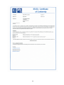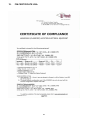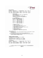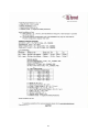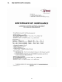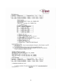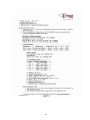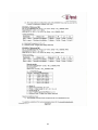
1
EE300Ex Series HUMIDITY / TEMPERATURE TRANSMITTER For Intrinsically Safe Applications Operating instructions BA_EE300EX_e // v1.7 / Technical data subject to change // 302484 The operating instructions form part of the equipment supplied and are used to ensure optimal operation and functioning of the device. E+E Elektronik® Ges.m.b.H. provides no warranty of any kind on this publication and no liability for improper use of the products described. To ensure perfect functioning, these operating instructions must be read carefully and observed before the transmitter is commissioned. These instructions must be provided to all persons responsible for mounting, commissioning, operation, inspection, maintenance and repair. These operating instructions must not be used for the purposes of competition without our written permission and must not be forwarded to third parties. Copies may be made for internal purposes. All information, technical data and technical diagrams included in these instructions were correct in accordance with the data available at the time of writing. The company E+E Elektronik GmbH reserves the right to make modifications at any time and without prior notification, with no update requirement on models produced before the modification date. For this reason, we request that you contact our customer service department, quoting the device number, designation and type given on the nameplate. © Copyright E+E Elektronik Ges.m.b.H. All rights reserved. USA FCC notice: This equipment has been tested and found to comply with the limits for a Class B digital device, pursuant to part 15 of the FCC Rules. These limits are designed to provide reasonable protection against harmful interference in a residential installation. This equipment generates, uses and can radiate radio frequency energy and, if not installed and used in accordance with the installation manual, may cause harmful interference to radio communications. However, there is no guarantee that interference will not occur in a particular installation. If this equipment does cause harmful interference to radio or television reception, which can be determined by turning the equipment off and on, the user is encouraged to try to correct the interference by one or more of the following measures: - - - - Reorient or relocate the receiving antenna. Increase the separation between the equipment and receiver. Connect the equipment into an outlet on a circuit different from that to which thereceiver is connected. Consult the dealer or an experienced radio/TV technician for help. CANADIAN ICES-003 Issue 5: CAN ICES-3 B / NMB-3 B 2 Contents 1. GENERAL NOTES 1.1 1.2 Explanation of symbols Safety instructions 1.3 Environmental aspects 1.2.1 2. 3. 6. General safety instructions 4 4 TECHNICAL DESCRIPTION 5 5 6 7 10 11 11 11 Installation in an explosion hazard area 12 3.1General 3.2 Housing assembly Drilling plan for the housing 12 13 13 3.3 3.4 3.5 Assembly in category 1 (zone 0 / 20); Division 1 Assembly in categories 2 and 3 (Zone 1 2 / 21 22), Division 2 Mounting the measurement sensor 14 15 16 3.6 3.7 Calculation of the maximum cable length Selecting a suitable power supply device for ATEX Zone concept: 20 20 3.5.1 3.5.2 3.5.3 3.5.4 5. 4 4 2.1General 2.2 EE300Ex labeling 2.3Certification 2.4 Housing and probe dimensions 2.5 Humidity probe working range 2.6 Dewpoint measurement in natural gas 2.7 Measurement of moisture in oil 3.2.1 4. 4 Mounting Mounting Mounting Mounting the clamping ring screw connection with mounting flange (optional) the probe using ball valve (optional) the probe using sensor retraction tool (optional) 16 17 18 19 ELECTRICAL CONNECTIONS 22 DISPLAY (optional) 25 4.1 4.2 4.3 4.4 4.5 Connecting cable Terminal assignment EE300Ex Configuration adapter Calibration of the current loop Grounding and potential equalization 22 23 23 23 24 MAINTENANCE26 6.1 Filter replacement 6.2Cleaning 26 26 6.3 6.4 26 26 6.2.1 6.2.2 Cleaning the display Cleaning the sensor Customer adjustment of humidity and temperature Ordering information for accessories 26 26 7. Technical data - EE300EX-ht 27 8. Technical data - EE300Ex-xT28 9. ATEX certificatE 29 10. EC Declaration of Conformity 34 11. IECEX CERTIFICATE OF CONFORMITY - COC 35 12. fm certificate usa 39 13. fm certificate CANADA 46 14. control drawing m1_1309080 53 3 1. GENERAL NOTES 1.1 Explanation of symbols This symbol indicates safety information. It is essential that this safety information is followed. The manufacturer accepts no liability in the case of contravention. The risk is borne solely by the user. This symbol indicates an instruction. These instructions should be observed to achieve optimum functioning of the device. This symbol indicates regulations that must be observed in hazardous areas at risk of explosion. 1.2 Safety instructions 1.2.1 General safety instructions In the event of improper or incorrect use of the device, the following risks occur: • Hazards for the device and other assets of the user as well as • Hazards that impair the efficient working of the device. The following instructions should be observed to ensure personal safety: • Only qualified or specially trained personnel should be permitted to work on or operate the device. • These operating instructions must always be available to all persons carrying out mounting, commissioning, operation and servicing. • It is essential that the device is only operated when in perfect operating condition. • Any faults determined must be rectified immediately by specialist personnel or by E+E Elektronik customer services. • No technical modifications to the device are permitted. • Take care when unscrewing the filter cap as the sensor element may be damaged in the process. • The sensor element is an ESD-sensitive component, i.e. ESD safety measures must be observed when touching the sensor element. • Only touch sensors on the connecting wires. • The devices are designed for operation on safety extra-low voltage (safety class III). 1.3 Environmental aspects Products from E+E Elektronik® are developed incorporating all important environmental aspects. For this reason, avoiding environmental contamination should also be observed during disposal as well. On disposal of the transmitter, the individual components must be separated by type. The electronics must be collected in electronics waste and disposed of correctly. 4 2. TECHNICAL DESCRIPTION 2.1General The entire EE300Ex transmitter can be installed directly in the explosion hazard area. The EE300Ex is the ideal transmitter in challenging industrial applications. The housing and measurement sensor made from stainless steel, as well as the proven E+E humidity sensors, ensure reliable and stable measurement results over long periods. The EE300Ex has a 2-wire design and has two individually scalable analogue outputs with 4…20mA. In addition to the measured values for relative humidity and temperature, the transmitter also delivers the following calculated values: • • • • • • • • • • Absolute humidity Wet-bulb temperature Specific enthalpy Dew-point temperature Frost point temperature Mixing ratio Water vapour partial pressure Water activity Water content in mineral transformer oil Water content in customer-specific oil dv Tw h Td Tf r e aw x [ppm] x [ppm] The EE300Ex-HT humidity / temperature transmitter is available in the following designs: Model A - wall mounting remote sensing probe up to 20bar (300psi) E - remote sensing probe up to 20bar (300psi) with moveable fitting for assembly / disassembly under pressure M - remote sensing probe up to 300bar (4351psi) U - remote sensing probe for sensor retraction tool PN250 pressure range 0.1...20 bar 0.1...20 bar (1.5...300 psi) (1.5...300 psi) working range -40...60°C (-40...140°F) -40...180°C (-40...356°F) -40...180°C (-40...356°F) 0.01...300 bar (0.15...4351 psi) -40...180°C 0.01...300 bar (0.15...4351 psi) -40...180°C (-40...356°F) (-40...356°F) Ø-probe 12mm (0.47“) 12mm (0.47“) 13mm (0.51“) 12mm (0.47“) 12/15 (0.47/0.59) The EE300Ex-xT temperature transmitter is available in the following designs: Model A - wall mounting M - remote sensing probe pressure range 0.1...20bar (1.5...300psi) 5 working range Ø-probe -40...60°C (-40...140°F) 6mm (0.24“) -70...200°C (-94...392°F) 6mm (0.24“) 2.2 EE300Ex labeling Each EE300Ex is only characterized for one certificate. The Ordering Code on the Product label shows the type of the Ex Certificate on position “Ex-certificate”. The exact Ex marking with the certificate number is printed on the Hazardous label (Ex marking). EE300Ex with IECEx, USA or Canada labeling must not be installed in the European Union. Hazardous Label (Ex marking) ATEX hazardous label Product Label ATEX product label (Example) (for EE300Ex without display) IECEx hazardous label IECEx product label (Example) (for EE300Ex without display) USA/CANADA hazardous label USA/CANADA product label (Example) (for EE300Ex without display) 6 2.3Certification EUROPE: The EE300Ex transmitter fulfils the ATEX Directives on intrinsically safe operating equipment. Applied standards for ATEX: • EN 1127-1:2011 • EN 60079-0:2012 • EN 60079-11:2012 The EC type approval test has been carried out by TÜV SÜD Product Service GmbH. Certified to EC type approval test TPS 13 ATEX 38892 003 X. Ui = 28V; Ii = 100mA; Pi: = 700mW; Ci = 2,2nF; Li ≈ 0mH Entity parameters Ex-Designation Transmitter without display II 1 G Ex ia IIC T4 Ga / II 1 D Ex ia IIIC T80°C Da Transmitter with display II 2 G Ex ia IIC T4 Gb / II 1 G Ex ia IIB T4 Ga Remote sensing probe II 1 G Ex ia IIC T6-T1 Ga / II 1 D Ex ia IIIC T80°C...200°C Da Working temperature range for the probes: Specification of the temperature class "TKG" for use in gas area exposed to explosion hazards and "TKD" for use in dust area exposed to explosion hazards as a function of the ambient temperature "Tamb" for the humidity and temperature probe and the temperature probe: TKG TKD Humidity and Temperature Probe TKG TKD Temperature Probe -70°C ≤ Tamb ≤ +60°C T6 80°C -40°C ≤ Tamb ≤ +60°C T6 80°C T5 95°C -40°C ≤ Tamb ≤ +75°C T5 95°C -70°C ≤ Tamb ≤ +75°C T4 130°C -40°C ≤ Tamb ≤ +110°C T4 130°C -70°C ≤ Tamb ≤ +110°C -70°C ≤ Tamb ≤ +175°C T3 195°C -40°C ≤ Tamb ≤ +175°C T3 195°C T2 200°C -40°C ≤ Tamb ≤ +180°C T2 220°C -70°C ≤ Tamb ≤ +200°C T1 200°C -40°C ≤ Tamb ≤ +180°C T1 220°C -70°C ≤ Tamb ≤ +200°C INTERNATIONAL: Applied Standard for IECEx: • IEC 60079-0:2011 • IEC 60079-11:2011 The Certificate of Conformity has been carried out by FM Approvals. Certificate No.: IECEx FMG 14.0017 X Entity parameters: 6.4 Vdc ≤ Ui ≤ 28Vdc; Ii = 100mA; Pi = 700mW; Ci = 2,2nF; Li = 0mH Ex-Designation Transmitter without display Ex ia IIC T4 Ga / Ex ia IIIC T131°C Da Transmitter with display Ex ia IIC T4 Gb / Ex ia IIB T4 Ga Remote sensing probe Ex ia IIC T6-T1 Ga / Ex ia IIIC T80°C Da Humidity and temperature probe: • • • • • • T6 T5 T4 T3 T2 T1 temperature temperature temperature temperature temperature temperature Temperature probe: • • • • • • T6 T5 T4 T3 T2 T1 temperature temperature temperature temperature temperature temperature class class class class class class based based based based based based on -40°C on -40°C on -40°C on -40°C on -40°C on -40°C (-40°F) (-40°F) (-40°F) (-40°F) (-40°F) (-40°F) ≤ Ta ≤ Ta ≤ Ta ≤ Ta ≤ Ta ≤ Ta ≤ ≤ ≤ ≤ ≤ ≤ 60°C (140°F) 75°C (167°F) 110°C (230°F) 175°C (347°F) 180°C (356°F) 180°C (356°F) class class class class class class based based based based based based on -70°C on -70°C on -70°C on -70°C on -70°C on -70°C (-94°F) (-94°F) (-94°F) (-94°F) (-94°F) (-94°F) ≤ Ta ≤ Ta ≤ Ta ≤ Ta ≤ Ta ≤ Ta ≤ ≤ ≤ ≤ ≤ ≤ 60°C (140°F) 75°C (167°F) 110°C (230°F) 175°C (347°F) 200°C (392°F) 200°C (392°F) 7 USA: Applied Standard for the U.S. NEC 500, NEC505 and 506: • FM Class 3600 2011 • FM Class 3610 2010 • FM Class 3611 2004 • FM Class 3810 2005 • ANSI/ISA 61010-1 2004 • ANSI/ISA 60079-0 2009 • ANSI/ISA 60079-11 2011 The Certificate of Conformity has been carried out by FM Approvals. Entity parameters: 6.4 Vdc ≤ Vmax (or Ui) ≤ 28 Vdc; Imax (or Ii) = 100mA; Pi = 700mW; Ci = 2,2nF; Li = 0mH Ex-Designation NEC 500 (Division) Transmitter without display IS / I,II,III / 1 / ABCDEFG / T4 Ta = 60°C NI / I,II,III / 2 / ABCDEFG / T4 Ta = 60°C Transmitter with display IS / I / 1 / CD / T4 Ta = 60°C IS / I / 2 / ABCD / T4 Ta = 60°C NI / I / 2 / ABCD / T4 Ta = 60°C Remote sensing probe IS / I,II,III / 1 / ABCDEFG / T6-T1 NI / I,II,III / 2 / ABCDEFG / T6-T1 Humidity and temperature probe: • • • • • • T6 T5 T4 T3 T2 T1 temperature temperature temperature temperature temperature temperature class class class class class class based based based based based based on -40°C on -40°C on -40°C on -40°C on -40°C on -40°C (-40°F) (-40°F) (-40°F) (-40°F) (-40°F) (-40°F) ≤ Ta ≤ Ta ≤ Ta ≤ Ta ≤ Ta ≤ Ta ≤ ≤ ≤ ≤ ≤ ≤ 60°C (140°F) 75°C (167°F) 110°C (230°F) 175°C (347°F) 180°C (356°F) 180°C (356°F) • • • • • • T6 T5 T4 T3 T2 T1 temperature temperature temperature temperature temperature temperature class class class class class class based based based based based based on -70°C on -70°C on -70°C on -70°C on -70°C on -70°C (-94°F) (-94°F) (-94°F) (-94°F) (-94°F) (-94°F) ≤ Ta ≤ Ta ≤ Ta ≤ Ta ≤ Ta ≤ Ta ≤ ≤ ≤ ≤ ≤ ≤ 60°C (140°F) 75°C (167°F) 110°C (230°F) 175°C (347°F) 200°C (392°F) 200°C (392°F) Temperature probe: Ex-Designation NEC 505/506 (Zone) Transmitter without display I / 0 / AEx ia / IIC / T4 Ta = 60°C 20 / AEx ia / IIIC / T131°C Transmitter with display I / 0 / AEx ia / IIB / T4 Ta = 60°C I / 1 / AEx ia / IIC / T4 Ta = 60°C Remote sensing probe I / 0 / AEx ia / IIC / T6-T1 20 / AEx ia / IIIC / T80°C Humidity and temperature probe: • • • • • • T6 T5 T4 T3 T2 T1 temperature temperature temperature temperature temperature temperature Temperature probe: • • • • • • T6 T5 T4 T3 T2 T1 temperature temperature temperature temperature temperature temperature class class class class class class based based based based based based on -40°C on -40°C on -40°C on -40°C on -40°C on -40°C (-40°F) (-40°F) (-40°F) (-40°F) (-40°F) (-40°F) ≤ Ta ≤ Ta ≤ Ta ≤ Ta ≤ Ta ≤ Ta ≤ ≤ ≤ ≤ ≤ ≤ 60°C (140°F) 75°C (167°F) 110°C (230°F) 175°C (347°F) 180°C (356°F) 180°C (356°F) class class class class class class based based based based based based on -70°C on -70°C on -70°C on -70°C on -70°C on -70°C (-94°F) (-94°F) (-94°F) (-94°F) (-94°F) (-94°F) ≤ Ta ≤ Ta ≤ Ta ≤ Ta ≤ Ta ≤ Ta ≤ ≤ ≤ ≤ ≤ ≤ 60°C (140°F) 75°C (167°F) 110°C (230°F) 175°C (347°F) 200°C (392°F) 200°C (392°F) 8 Canada: Applied Standard for Canada CEC Section 18 and Annex J: • CSA 22.2 No. 0-M91 2006 • CSA 22.2 No. 61010-1 2004 • CSA 22.2 No. 157 2006 • CSA 22.2 No. 60079-0 2007 • CSA 22.2 No. 60079-11 2011 • CAN/CSA C 22.2 No. 142-M1987 2004 • CAN/CSA C 22.2 No. 213-M1987 2004 The Certificate of Conformity has been carried out by FM Approvals. Entity parameters: 6.4 Vdc ≤ Vmax (or Ui) ≤ 28 Vdc; Imax (or Ii) = 100mA; Pi = 700mW; Ci = 2,2nF; Li = 0mH Ex-Designation CEC Section 18 and Annex J (Division) Transmitter without display IS / I,II,III / 1 / ABCDEFG / T4 Ta = 60°C NI / I / 2 / ABCD / T4 Ta = 60°C Transmitter with display IS / I / 1 / CD / T4 Ta = 60°C IS / I / 2 / ABCD / T4 Ta = 60°C NI / I / 2 / ABCD / T4 Ta = 60°C Remote sensing probe IS / I,II,III / 1 / ABCDEFG / T6-T1 NI / I / 2 / ABCD/ T6-T1 Humidity and temperature probe: • • • • • • T6 T5 T4 T3 T2 T1 temperature temperature temperature temperature temperature temperature Temperature probe: • • • • • • T6 T5 T4 T3 T2 T1 temperature temperature temperature temperature temperature temperature class class class class class class based based based based based based on on on on on on -40°C -40°C -40°C -40°C -40°C -40°C (-40°F) (-40°F) (-40°F) (-40°F) (-40°F) (-40°F) ≤ Ta ≤ Ta ≤ Ta ≤ Ta ≤ Ta ≤ Ta ≤ ≤ ≤ ≤ ≤ ≤ 60°C (140°F) 75°C (167°F) 110°C (230°F) 175°C (347°F) 180°C (356°F) 180°C (356°F) class class class class class class based based based based based based on on on on on on -70°C -70°C -70°C -70°C -70°C -70°C (-94°F) (-94°F) (-94°F) (-94°F) (-94°F) (-94°F) ≤ Ta ≤ Ta ≤ Ta ≤ Ta ≤ Ta ≤ Ta ≤ ≤ ≤ ≤ ≤ ≤ 60°C (140°F) 75°C (167°F) 110°C (230°F) 175°C (347°F) 200°C (392°F) 200°C (392°F) Ex-Designation CEC Section Transmitter without display Transmitter with display Remote sensing probe 18 (Zone) I / 0 / Ex ia I / 0 / Ex ia I / 1 / Ex ia I / 0 / Ex ia Humidity and temperature probe: • • • • • • T6 T5 T4 T3 T2 T1 temperature temperature temperature temperature temperature temperature Temperature probe: • • • • • • T6 T5 T4 T3 T2 T1 temperature temperature temperature temperature temperature temperature / / / / IIC / T4 Ta = 60°C Ga IIB / T4 Ta = 60°C Ga IIC / T4 Ta = 60°C Gb IIC / T6-T1 Ga class class class class class class based based based based based based on -40°C on -40°C on -40°C on -40°C on -40°C on -40°C (-40°F) (-40°F) (-40°F) (-40°F) (-40°F) (-40°F) ≤ Ta ≤ Ta ≤ Ta ≤ Ta ≤ Ta ≤ Ta ≤ ≤ ≤ ≤ ≤ ≤ 60°C (140°F) 75°C (167°F) 110°C (230°F) 175°C (347°F) 180°C (356°F) 180°C (356°F) class class class class class class based based based based based based on -70°C on -70°C on -70°C on -70°C on -70°C on -70°C (-94°F) (-94°F) (-94°F) (-94°F) (-94°F) (-94°F) ≤ Ta ≤ Ta ≤ Ta ≤ Ta ≤ Ta ≤ Ta ≤ ≤ ≤ ≤ ≤ ≤ 60°C (140°F) 75°C (167°F) 110°C (230°F) 175°C (347°F) 200°C (392°F) 200°C (392°F) 9 2.4 Housing and probe dimensions Wall mounting humidity and temperature - Model A 179 (7“) 151 (5.9“) 60 (2.4“) Length in mm Stainless steel sinter filter 33 (1.3“) PTFE filter 33 (1.3“) Stainless steel grid filter 39 (1.5“) Oil filter 32 (1.26“) L 53 (2.1“) 98 (3.9“) L = filter cap Remote sensing probe humidity/temperature up to 300 bar (4351 psi) - Model U Cable length acc. to order code 186 (7.32) 15 (0.6“) 15 (0.6“) Probe length 300 (11.8") 12 (0.47“) L cut-in fitting 1/2" ISO Remote sensing probe humidity/temperature up to 20bar (300psi) or 300 bar (4351 psi) Model E and M Cable length acc. to order code Probe length 65 (2.6") / 200 (7.9") / 400 (15.7") 12 (0.47“) L 15 (0.6“) cut-in fitting 1/2" ISO, NPT or welded fitting Pressure-tight probe up to 300 bar (4351 psi) have a leak rate A according to EN12266-1 Remote sensing probe humidity/temperature up to 20bar fitting (300psi) - Model E with sliding Cable length acc. to order code 15 (0.6“) (0.47“) Probe length 200 (7.9") / 400 (15.7") Ø12 Ø13 (0.51“) L adjustable min. 23 (0.9”) / max. 164 (6.5”) / 364 (14.3”) Sliding fitting 1/2" ISO or NPT Pressure-tight probe up to 20bar (300psi) have a leak rate B according to EN12266-1 10 Wall mounting temperature - xT model 179 (7“) 151 (5.9“) 70 (2.8“) 98 (3.9“) 60 (2.4“) Remote sensing probe temperature Cable length acc. to order code Ø6 (0.24“) 150 (6“) 2.5 Single-sided screw connection 1/2" ISO or NPT Humidity probe working range Relative humidity [% rel. hum.] The grey area shows the allowed measurement range for the humidity sensor. Although working points that lie outside of this range do not lead to the destruction of the element, the specified measurement accuracy cannot be guaranteed, however. Temperature [°C] 2.6 Dewpoint measurement in natural gas Valid only for EE300Ex-HT6S...Gx (Special option for natural Gas application) The accuracy of the dewpoint measurement is affected by the working pressure. The actual working pressure has to be set with the configuration software. Menu item "Configuration" --> "Parameters" Factory setting: 1013.25 mbar 2.7 Measurement of moisture in oil Besides measurement in the air, the EE300Ex can be employed for measurement of both absolute water content (x) in ppm or relative water activity (aw) in oils. The USA and Canada approval is valid for air and gas measurement only. 11 3. Installation in an explosion hazard area 3.1General The EE300Ex has been certified in accordance with the ATEX 94/9EC Directive, IECEX Scheme, , National Electrical Code (ANSI-NFPA 70 (NEC©) and Canadian Electrical Code (CSA C22.1). Devices in explosion-hazard areas are only permitted for operation in atmospheric conditions -20 °C (-4°F) ≤ T ≤ 40 °C (104 °F) 0.8 bar (12 psi) ≤ p ≤ 1.1 bar (16 psi) In air normally 21 % (V/V) If suitable measures have been carried out in accordance with EN1127-1, the EE300Ex is also permitted for operation outside atmospheric conditions in line with the manufacturer's instructions. When conducting measurements in explosion-hazard areas, the EE300Ex must always be connected via intrinsically safe power supply devices or protective barriers. Even if only the measurement probe is installed in the explosion hazard area, the EE300Ex must be supplied using intrinsically safe equipment. Rules for the interconnection of intrinsically safe electrical circuits in accordance with EN60079-14, EN60079-25 and IEC60079-14, IEC60079-25 (proof of intrinsic safety in the system description) and national requirements should be followed. For the U.S., Canada see Controll Drawing M1_1309080 and ANSI/ISA RP12.6.01, NEC and CEC. If a risk analysis of the installation in line with EN1127-1 reveals a risk of lightning strike, an overvoltage protection device should be installed in the intrinsically safe circuits. Requirements for the installation of overvoltage protective devices can be found in the standard EN60079-25. For the U.S., Canada see ANSI/ISA RP12.6.01, NEC and CEC. Example of an overvoltage protection device Manufacturer:Dehn Type: ITAK EXI BXT 24 to protect intrinsically safe measurement circuits for 2DA C2 nominal discharge surge current: (8/20) 20 kA Nominal voltage: 30 V DC max. permiss. input voltage: 33 V DC max. permiss. input current: 0.5 A Alu housing, grey, protection rating: IP 65 ATEX Approval: II 2 (1) G Ex ia IIC T4, T5, T6 II 2 G Ex ib IIC T4, T5, T6 Follow the installation instructions from DEHN! Each EE300Ex is provided with its production date. The production date is shown on the label (after the series) as follows: WWYYYYWW week of the year of construction YYYY year of construction 12 3.2 Housing assembly The EE300Ex housing has a two-part construction. • Lower housing section with the connection and earthing terminals. • Upper housing section with the electronics and measurement probe. Upper housing part Lower housing part 3.2.1 Drilling plan for the housing 167 (6.6") 4.5 (0.18") 70 (2.8") The lower housing section is mounted using 4 screws. Screw diameter < 4.5mm (0.18") If the upper housing section is removed from the hazard area, e.g. for a calibration, the empty lower section should be protected against dirt and electrostatic charge via a cover HA011401. Unused cable glands should be sealed using a sealing plug. 13 3.3 Assembly in category 1 (zone 0 / 20); Division 1 Only intrinsically safe power supply devices are approved to supply EE300Ex in category 1 or Division 1. In areas belonging to gas group IIC or Class I, Division 1, Group A,B, it must be ensured that during installation and operation, the possibility of impact and friction sparks has been excluded in rarely occurring fault situations. Work on open transmitter must only be performed if it is guaranteed that no explosive atmosphere is present. In category 1 or Division 1, the sensor line should be laid in an earthed metallic protective hose. With Group III or Class II, III, ensure that there are no dust or fibers and flyings deposits in the protective tube. CH1 and CH2 must be galvanically isolated from one another during operation. There is no display permitted in the gas hazard area EPL Ga for Group IIC or Class I, Division 1, group A, B, and in the dust hazard area for groups IIIA, IIIB and IIIC or Class II, III. The probe for wall mounting is not permitted to be used for Zone or Division bushing. EE300Ex (wall mounting) 1 channel via intrinsically safe power supply device: Unclassified location Hazardous location T4...T1 Zone 0 / 20 no display with EPL Da; Db, Dc and Ga IIC Zone 1 2 / 21 22 Division 2 Division 1 no display in Class II, III and Class I, Division 1, Group A, B CH1 Control CH2 intrinsically safe transmitter supply unit 4-20mA ia + + - - L+ Power supply + - L- EE300Ex (with remote sensing probe) 2 channels via intrinsically safe power supply device: Hazardous location T6...T1 Zone 0 / 20 Division 1 Class I,II,III Group A, B, C, D, E, F, G Unclassified location Zone 1 2 / 21 22 Division 2 Class I,II,III Group A, B, C, D, E, F, G intrinsically safe transmitter supply unit up to T6 if EE300Ex is in unclassified location. CH1 CH2 + + - - + + - - Control 4-20mA ia 4-20mA ia The bushing must conform to the hazard requirements of a Zone or Division implementation. The supplied screw connection meets this requirement! L+ L- 14 + - Power supply 3.4 Assembly in categories 2 and 3 (Zone 1 2 / 21 22), Division 2 Only intrinsically safe power supply devices and protective barriers are approved to supply EE300Ex in category 2 and 3 or Division 2. No display is permitted in the dust hazard area (Group III) or Class II, III. CH1 and CH2 must be galvanically isolated from one another during operation. The probe for wall mounting is not permitted to be used for Zone or Division bushing. EE300Ex (wall mounting) 1 channel via intrinsically safe power supply device: Hazardous location T4...T1 Unclassified location Zone 1 2 / 21 22 Division 2 Class I,II,III Group A, B, C, D, E, F, G, H Control CH2 CH1 intrinsically safe transmitter supply unit 4-20mA ia + + - - L+ L- + - Power supply EE300Ex (with remote sensing probe) 2 channels via intrinsically safe power supply device: Hazardous location T4...T1 Zone 0 / 20 Division 1 Class I,II,III Group A, B, C, D, E, F, G, H Unclassified location Zone 1 2 / 21 22 Division 2 Class I,II,III Group A, B, C, D, E, F, G, H intrinsically safe transmitter supply unit CH1 CH2 + + - - + + - - Control 4-20mA ia 4-20mA ia The bushing must conform to the hazard requirements of a Zone or Division implementation. The supplied screw connection meets this requirement! L+ L- 15 + - Power supply 3.5 Mounting the measurement sensor To mount the transmitter, select a location with stable conditions, i.e. protected against direct sunlight or rain. The measurement probe should be fitted at a location where representative measured values are to be anticipated for the process. Wand / Wall r > 30mm The measurement probe must be mounted horizontally or vertically (downwards). If possible, a drip tray should be placed into position before every installation. A temperature drop along the measurement sensor should be avoided. 60% rH Relative Humidity Temperature 45% rH 21°C 17°C Mechanical ambient conditions When installing the sensor, the mechanical influences of the installation site should be taken into account. (e.g. vibrations, shock loads via startup processes, temperature fluctuations,...). If the mechanical stability or seal on the probe cannot be ensured, additional mechanical fastening or support should be included. The probe cable and connection cable should be handled and laid in the hazard area so that no static charges can arise (e.g. metal hose). Filter caps The following filter caps ensure sufficient protection against electrostatic discharges relating to explosion group IIB, but are not permitted for use in EPL Ga IIC or Class I, Division 1, Group A,B: • PTFE filter (order code E) • PTFE filter on metal body (order code K) • H2O2 filter (order code L) The following filter caps are permitted for use in EPL Ga IIC or Class I, Division 1, Group A,B: • Stainless steel sinter filter (order code D) • Stainless steel lattice filter (order code I) • Oil filter (order code M) 3.5.1 Mounting the clamping ring screw connection The clamping ring screw connection can be used as Zone or Division bushing. To do this, the screw connection is screwed into the isolating wall and must have a seal tightness of IP67. Safety instructions for pressure-tight screw connection: • The system must not be vented by releasing the union nuts. • Do not assemble and tighten pipe screw connections if the system is under pressure. • Always use the correct thread sealant on conical pipe threads. • Never rotate the screw connection body. Instead, hold the screw connection body securely and turn the union nut. • Avoid unnecessary disassembly of unused pipe screw connections. 16 Installation instructions: • Tighten the union nuts finger-tight. • Mark the union nuts at the 6 o' clock position. • Hold the screw connection body tight and tighten the union nuts with 1 ¼ turns to the 9 'o clock position. Assembly with high pressure applications and applications with a high security factor: • Tighten the union nuts until the pipe can no longer be turned by hand or can no longer be moved axially in the fitting. • Mark the union nuts at the 6 o' clock position. • Hold the screw connection body tight and tighten the union nuts with 1 ¼ turns to the 9 'o clock position. Re-mounting: • Slide measurement sensor with clamping rings into the fitting as far as it will go. • Tighten the nut "fingertight", then tighten by approx. a ¼ turn using a spanner. 3.5.2 Mounting with mounting flange (optional) The assembly flange must not be used as Zone or Division bushing, i.e. it must only be used for fastenings and bushings in explosion-hazard areas of the same category. 13mm (0.5") The measurement sensor must be mounted horizontally or vertically (downwards). If possible, a drip tray should be placed into position before every installation. Horizontal mounting Vertical mounting 17 3.5.3 Mounting the probe using ball valve (optional) With ball valve mounting, the system being measured does not need to be emptied or brought to a standstill to mount or remove the probe. Install the sensor head against the flow direction. Metal sealing ring Metal sealing ring It is only permitted to use one ball valve that is approved for use in explosion hazard areas. (included with the ball valve set as standard) (as standard with probe) The process pressure must be below 10bar (145psi). The two metal sealing rings (see figure) should be replaced each time after being screwed on. MOUNTING THE PROBE: Extension (not provided with an NPT thread) The mounting temperature is not permitted to deviate from the usage temperature by more than ±40°C (104°F). • • • • Internal diameter: ≥ 13.1 mm (0.51") Mount the probe with the ball valve closed. Open the ball valve. Insert the sensor head through the ball valve into the process. A manual pressing tool is recommended at high pressure. To ensure that the probe is securely installed, the closing nut must be tightened at a defined torque of 30Nm. If there is no torque wrench present, tighten the closing nut by hand as far as possible. Turn another ~50° using a suitable open-ended spanner. A tightening torque that is too low results in a lower clamping force (fixing force) of the clamp sleeve. There is therefore a risk of injury due to the probe tube being driven out. An excessively high tightening torque can result in the permanent deformation of the clamping sleeve and the probe tube. This makes the removal and re-mounting process more difficult or impossible. REMOVING THE PROBE: • • • • Hold the probe tube tight. (Caution: Do not bend the connection cable) Slowly unfasten the closing nut using a spanner (spanner size 24) until the driveout force affects the tube. Never fully remove the closing nut when installed, and instead screw on only as far as possible! After the sensor head has been removed from the process as far as it will go, close the ball valve. The probe can be fully removed. Both for mounting and removal, ensure that O-ring 1 is correctly installed. If damaged, O-ring 1 can be replaced by the user. O-ring type: 13x1.5mm (0.5"x 0.06") - FKM-60 Spare part order no. HA050308 18 Clamp sleeve Sealing nut Fitting body O-ring 2 O-ring 1 no aluminium is permitted 3.5.4 Mounting the probe using sensor retraction tool (optional) Observe the operating instructions of the sensor retraction tool! It may only be used the sensor retraction tool ZM-WA-025-040-EST or BG-WA-103-045-EST. With the sensor retraction tool 250 bar it may only be used the sensor probe model U. The delivery scope of the sensor probe includes the copper sealing for the Swagelok screw connection. Make sure that the sensor retraction tool is in ”SERVICE“ position (see manual of the sensor retraction tool). • Before installing the sensor, dismount the closing plug ½“ by means of a hexagonal wrench 10 mm and “park“ it at the thread hole M10 designed for that purpose. • Insert the sensor with copper sealing Swagelok and protective cover into the sensor retraction tool until the stop position. protective cover Swagelok-union nut Swagelok-fitting copper sealing • Fasten the Swagelok screw conneciton ½“ in the sensor retraction tool with the open-jaw wrench (wrench size 27mm). Do not forget to check the copper sealing! • At first manually tighten the Swagelok union nut with cutting ring. Pull back the probe until it stops and hold it. • By means of a screw wrench, tighten the union nut just firmly enough that the screw connection cannot be moved manually any longer. Mark the union nuts at the 6 o' clock position. • Hold the screw connection body tight and tighten the union nuts with 1 ¼ turns to the 9 'o clock position. • To mount the protective cover for the Swagelok protective cover, proceed in the following order: • Push the protective cover down to the adjusting device: screws must point to the flat area (wrench size 26mm) • Tighten screws M3. 19 3.6 Calculation of the maximum cable length Intrinsically safe power supply device STAHL 9160/13-11-11 (order code HA011405) Technical data for EE300Ex UBin= 9V + RL * 0.02A Iout max = 20mA Supply voltage: Max. current: Technical data for STAHL 9160/13-11-11 UN = 24V US= 16V RL = 600Ohm Nominal operating voltage: Input voltage for transmitter: Max. load: Calculation of maximum cable length of intrinsically safe input isolator Cable 0.75mm² (0.01in2) (example):Rcable = 0.0267Ω/m Load resistance (load): RL = 200Ω Input voltage for transmitter: US= 16V Min. supply voltage EE300Ex: UBmin = 9V + 200Ω * 0.02A = 13V Maximum voltage drop on cable: Ucable = US - UBmin = 16V – 13V = 3V Total cable resistance: Rcable total = Rcable * Ltotal * 2 (supply and return line) Udrop = Rcable total * Iout max = = Rcable * Ltotal * 2 * Iout max Transform in accordance with LtotalLtotal = Udrop / (Iout max * 2 * Rcable ) Ltotal = 3V / (0.02A * 2 * 0.0267Ω/m ) Ltotal = 2800m maximum cable length Caution: this is the max. length without allowing for the intrinsic safety. (cable capacity and inductivity may reduce the length even further) 3.7 Selecting a suitable power supply device for ATEX Zone concept: Example for evidence of the intrinsic safety in accordance with EN60079-14:2008 12.2.5.2, EN60079-25:2010 13.1. CH1 and CH2 are galvanically separated, meaning the evidence of the intrinsic safety can only be carried out using appropriate equipment. Installation assumption: Installing the EE300Ex (without display) in Zone 0 Connecting cable length: 300m Explosion group: IIC Temperature class: T4 Both electric circuits laid in one cable. (984ft) Intrinsically safe power supply device STAHL 9160/13-11-11 (Excerpt from the EC type approval test certificate) Certified to: II 3 (1) G Ex nA nC [ia Ga] IIC T4 Gc (certificate number: DMT 03 ATEX E 010 X) II (1) D [Ex ia Da] IIIC (certificate number: DMT 03 ATEX E 010 X) Entity parameters: = 27V U0 I0 = 88mA P0 = 576mW C0 IIC = 90nF C0 IIB = 705nF L0 IIC = 2.3mH L0 IIB = 17mH 20 Technical data for connecting cable Cable type: ÖLFLEX® EB CY from manufacturer Lapp Kabel Cable cross-section: 4 x 0.75mm² (0.06x0.01in²) Operating capacity: 110nF/km Inductivity: 0.65mH/km Cable capacity for 300m (984ft): Cable inductivity for 300m (984ft): CK = 0.3km * 110nF/km = 33nF LK = 0.3km * 0.65mH/km = 0.195mH Technical data for EE300Ex (extract from the EC type approval test certificate) Certified to: II 1 G Ex ia IIC T4 Ga II 1 D Ex ia IIIC T80°C Da Entitiy parameters: Ui = 28V Ii = 100mA Pi = 700mW Ci = 2.2nF Li = negligibly small Evidence of the intrinsic safety in accordance with EN60079-11:2012 EN60079-25:2010 (Appendix A) U0 I0 P0 C0 L0 = = = = = 27V 88mA 576mW 90nF 2,3mH ≤ ≤ ≤ ≥ ≥ Ui = 28V Ii = 100mA Pi = 700mW 2,2nF + 33nF 0mH + 0,195mH → → → → → ok ok ok ok ok Protection level of the intrinsically safe current circuit is is met! Evidence of the intrinsic safety in accordance with EN60079-11:2012, EN60079-25:2010 (Appendix A) Li=0 YES NO Ci=0 YES NO Li≤1% of L0 YES NO Ci≤1% of C0 YES Full values of C0 and L0 can be utilised NO Use reduced C0 and L0 values for mixed electric circuits For intrinsically safe electric circuits with linear sources, simplified evaluation rule: each half value of C0 and L0 can be used, limited to C0 = 600nF (IIC) and 1 μF (IIB) Li = negligibly small → no reduced C0 and L0 values required! 21 4. ELECTRICAL CONNECTIONS It is essential that installation, electrical connection, commissioning, operation and maintenance in explosion hazard areas are only carried out by trained specialist personnel authorised to do so by the system operator. Installation in accordance with NEC or CEC with consideration of the Control Drawing M1_1309080 For installation in an explosion hazard area, it is essential to ensure that all relevant standards are observed. For the installation, standard EN60079-14, EN60079-25 or IEC60079-14, IEC60079-25 is to be applied, and for repair and maintenance, the standards EN60079-17 or IEC60079-17 and EN60079-19 or IEC60079-19 as well as the relevant national regulations should be applied. Installation in the U.S. must be carried out in accordance with ANSI / ISA RP 12.6.01-2003 and the National Electrical Code (NEC). Installation in Canada must be carried out in accordance with the Canadian Electrical Code (CEC). The EE300Ex is designed as a 2-wire current transmitter. CH1 should always be connected, CH2 can also be activated if required. Both outputs are galvanically isolated. Cable ends must be fitted with the appropriate wire-end sleeves. After the connection in the terminal, an air gap of at least 2mm (0.08") must be left between the strands and a 6mm (0.2") air gap between channels 1 and 2. Changes to the probe cable length are only permitted to be carried out by the manufacturer (transmitter will need to be re-calibrated). 4.1 Connecting cable A shielded cable should be used. The shield should be laid on one side with the EE300Ex. The cable must conform to the following specifications (requirements of EN60079-14, EN60079-25) for ATEX: • • • • • • Cable diameter 4 - 8mm (0.15-0.31") Maximum cross-section 1.5mm² (0.02in²) Single stranded wire diameter: ≥ 0.1mm (0.004") Test voltage wire-wire: ≥ 500V AC eff. Test voltage wire-shield (if a cable with shield is being used): ≥ 500V AC eff. Cable inductivity, cable capacity and conductor resistance are to be evaluated in the evidence of intrinsic safety • Flame-resistant acc. to IEC60332-1-2 Additional requirements if both channels (CH1, CH2) are connected in a common cable: • The test voltage wire-wire: must be ≥ 1000V AC eff. • The radial thickness of the insulation must be ≥ 0.2mm (0.008"). • The conductor insulation must withstand 500V AC eff. Cable ÖLFLEX® EB CY from manufacturer LAPP KABEL meets this requirement on request. 22 CH2 - CH2 + Configuration adapter CH1 - 4.3 CH1 + Terminal assignment EE300Ex Erde 4.2 The digital interface is used only for device configuration and customer adjustment. The configurator software and the drivers are available for download free of charge from our website http://www.epluse.com/en/service-support/download-center/. The EE300Ex in combination with the configurator software is only permitted for use outside the hazard area. It may only be used the cable with protective circuit (aluminum housing on the 8 pin connector). Connection from CH1 is NOT required for communication. RS232 (the external power supply required is included as standard with the configuration adapter): PC PC USB:PC Configuration adapter EE-PCA Connection cable - HA011061 PC If the upper housing section of the EE300Ex with the electronics and measurement probe is removed, the lower housing section with the blanking plate (HA011401) should be sealed to protect against dirt and electrostatic charge. 4.4 Calibration of the current loop Only appropriately approved multimeters are permitted for calibration in hazardous areas. During measurement with these multimeters, ensure that the requirements of the system description (proof of intrinsic safety) remain in force. 23 4.5 Grounding and potential equalization The EE300Ex must be integrated into the potential equalization to avoid hazards from electrostatic charges. It shall apply the requirements of the standards EN60079-14, EN60079-25 or IEC60079-14, IEC60079-25. With a remote sensing probe, the probe should also be integrated with the screw connection with a maximum of 1 MΩ in the potential equalization. The ground conductor or the potential equalization connection must have a cross-section of 4mm² (0.06in²) for the external earthing. With stranded wires, the cable ends should be fitted with suitable wire-end sleeves. Intrinsically safe barrier ground must be less than 1 ohm. For installation in the U.S. internal earthing should be used. The wire cross-sectional must be in accordance with NEC Section 250.122. External grounding: Cable cross-section maximum 4mm² (0.06in²) Internal grounding: Grounding connection channel 1 Grounding connection channel 2 Grounding connection occupied Cable cross-section maximum 10 mm² (0.2in2) Unclassified location SICHERER BEREICH Hazardous location EXPLOSIONSGEFÄHRDETER CH2 + CH2 - CH1 + CH1 - Erde BEREICH Instrument Instrument System System 1) potential equalization connection Safety barrier Sicherheitsbarriere oder or power Speisegerät supply unit Erdung der Barrieren grounding of barriers 1) Zentrale Erdung central grounding The braided screen should be turned back via the plastic insert on the cable connection. The introduction of the plastic insert presses the braided screen onto the interior wall of the metallic part. 24 5. DISPLAY (optional) There is no display permitted in the gas hazard area for EPL Ga IIC or Class I, Division 1, Group A, B and in the dust hazard area for IIIA, IIIB and IIIC or Class II, III. Measured values Units T:32.25°C Measured values selection top row RH:35.5% Measured values selection bottom row Measured values Example of EE300Ex wall mounting in Zone 1 or 2 or Division 2 Hazardous location T4...T1 Unclassified location Zone 1 2 Division 2 Class I Group A, B, C, D Control CH2 CH1 intrinsically safe transmitter supply unit 4-20mA ia up to IIC or Group A,B + + - - L+ + - L- Power supply Example of EE300Ex mounting of remote sensing probe in Zone 0 or Division 1 and transmitter in Zone 1 or 2 or Division 2 Hazardous location T4...T1 Zone 0 Division 1 Class I Group A, B, C, D Unclassified location Zone 1 2 Division 2 Class I Group A, B, C, D intrinsically safe transmitter supply unit CH1 up to IIC or Group A,B CH2 + - - + + - - Control 4-20mA ia 4-20mA ia metal filter caps + The bushing must conform to the hazard requirements of a Zone or Division implementation. The supplied screw connection meets this requirement! Power supply L+ L- 25 + - 6. MAINTENANCE It is essential that operation and maintenance in explosion hazard areas are only carried out by trained specialist personnel authorised to do so by the system operator. For maintenance and repair work in explosion hazard areas, the standards EN60079-17 or IEC60079-17, EN60079-19 or IEC60079-19 and the relevant national regulations must be applied. In the U.S. maintenance and inspection must be carried out in accordance with ANSI / ISA RP12.6.01-2003 and the NEC. In Canada maintenance and inspection must be carried out in accordance with CEC 6.1 Filter replacement The protective filter should be cleaned or replaced periodically, in particular whenever it has been noted that the response time has become longer. When replacing a filter, ensure that the sensor is NOT touching the metallic filter cap! 6.2Cleaning 6.2.1 Cleaning the display To clean the display screen, use a damp cloth to avoid static. 6.2.2 Cleaning the sensor Thanks to the very robust design of the sensor element, any cleaning required is very easy to carry out. This can be carried out using suitable chemicals such as isopropyl alcohol (normal industrial product). After cleaning in isopropyl alcohol, dip the sensor element in water and allow to dry. The cleaning time should not be more than 2 mins. To avoid damaging the sensor layer, the use of mechanical equipment is not permitted! When screwing on the filter cap, ensure that the sensor is NOT touching the metallic filter cap! 6.3 Customer adjustment of humidity and temperature See manual EE-PCS (product configuration software) 6.4 Ordering information for accessories Designation Order code Stainless steel sinter filter HA010103EX PTFE filter HA010105 Filter for moisture measurement in oil HA010110 Stainless steel lattice filter HA010109 Ball valve ISO 1/2" interior thread with ATEX approval HA011403 Configuration adapter for connection to the PC EE-PCA Connection cable with protective circuit between EE300Ex and configuration adapter HA011061 Blanking plate for lower housing part HA011401 Protective barrier STAHL 9002/13-280-093-001 HA011410 Intrinsically safe 1-channel power supply device STAHL 9160/13-11-11 HA011405 Intrinsically safe 2-channel power supply device STAHL 9160/23-11-11 HA011406 Sealing plug for unused cable screw connection HA011402 HA010201 Mounting flange 12mm (0.24") Mounting flange 6mm (0.24") HA010207 1/2" ISO screw connection 12mm (0.24")HA011102 1/2" NPT screw connection 12mm (0.24")HA011103 1/2" welded connection 12mm (0.5")HA011109 1/2" ISO screw connection 6mm (0.24")HA011104 1/2" NPT screw connection 6mm (0.24")HA011105 O-ring for sliding fitting HA050308 sensor retraction tool 250 bar ZM-WA-025-040-EST sensor retraction tool 40 bar BG-WA-103-045-EST 26 7. Technical data - EE300EX-ht Measuring values Relative humidity 1) Humidity sensor HC1000 1) 0...100% RH Measuring range Accuracy2) (including hysteresis, non-linearity and repeatability, traceable to international standards, administrated by NIST, PTB, BEV...) ± (1.3 + 0.3%*mv) % RH -15...40°C (5...104°F) ≤90% RH -15...40°C (5...104°F) >90% RH ± 2.3% RH -25...70°C (-13...158°F) ± (1.4 + 1%*mv) % RH ± (1.5 + 1.5%*mv) % RH -40...180°C (-40...356°F) Temperature dependence electronics typ. 0.03% RH/°C Response time with filter at 20°C (68°F) / t90 < 30 sec. Temperature Temperature sensor Measuring range sensor head Accuracy Pt1000 (Tolerance class A, DIN EN 60751) wall mounting: -40...60°C (-40...140°F) remote sensing probe: -40...180°C (-40...356°F) ∆°C °C typical 0.005 °C/°C Temperature dependence of electronics Max. selectable Scaling Range from Dew/Frost point temp. Td -40 (-40) Wet bulb temperature Tw 0 (32) Water vapour pressure e 0 (0) Mixing ratio r 0 (0) Absolute humidity dv 0 (0) Specific enthalpy H -50 (-15000) Water activity aw 0 Water content x 0 Outputs freely selectable and scalable outputs General Supply voltage (Class III) to wall mounting remote sensing probe 60 (140) 100 (212) 60 (140) 100 (212) 200 (3) 1100 (15) 425 (2900) 999 (9999) 150 (60) 700 (300) 400 (150000) 2800(999999) - 1 - 100000 2 x 4 - 20 mA (2-wire) galvanically isolated Output 1 (CH1) must be connected! unit °C (°F) °C (°F) mbar (psi) g/kg (gr/lb) 3 g/m (gr/ft3) kJ/kg(Btu/lb) [] [ppm] RL=(Vcc-9V)/20mA Vcc min=(9+RL*0.02)VDCVcc max=28VDC Current consumption max 20mA per channel Pressure range for pressure tight sensor probe refer to model Serial interface for communication 3)RS232 System requirements for software WINDOWS XP or later Protection class of housing IP65; NEMA 4 Cable gland M16 for cable diameter 5 - 10 mm (0.2 - 0.4“) Electrical connection screw terminals max. 1.5 mm² (AWG 16) Temperature range sensor head according measuring range electronic -40...60°C (-40...140°F) electronic with display -20...60°C (-4...140°F) Storage temperature range electronic and sensor head -20...60°C (22...140°F) Electromagnetic compatibility according EN61326-1 EN61326-2-3 ICES-003 ClassB Industrial Environment FCC Part15 ClassB Material Housing Stainless Steel 1.4404 Probe cable PTFE Probe (without Filter) Stainless Steel 1) Refer to the working range of the humidity sensor. 2) The accuracy statement includes the uncertainty of the factory calibration with an enhancement factor k=2 (2-times standard deviation). The accuracy was calculated in accordance with EA-4/02 and with regard to GUM (Guide to the Expression of Uncertainty in Measurement). 3) Configuration adapter EE-PCA and cabel HA011061 necessary. 27 8. Technical data - EE300Ex-xT Measuring values Temperature Temperature sensor Measuring range sensor head Accuracy1) Pt1000 (Tolerance class A, DIN EN 60751) wall mounting: -40...60°C (-40...140°F) remote sensing probe: -70...200°C (-94...392°F) ∆°C °C Temperature dependence of electronics Outputs Scaleable analogue output General Supply voltage (Class III) typ. 0.005 °C/°C 4 - 20 mA (2-wire) RL=(Vcc-9V)/20mA Vcc min=(9+RL*0.02)VDCVcc max=28VDC Current consumption max 20mA Pressure range for pressure tight sensor probe 0.1 ... 20bar (1.5...300psi) Serial interface for communication 2)RS232 System requirements for software WINDOWS XP or later Protection class of housing IP65; NEMA 4 Cable gland M16 for cable diameter 5 - 10 mm (0.2 - 0.4“) Electrical connection screw terminals max. 1.5 mm² (AWG 16) Temperature range Storage temperature range Electromagnetic compatibility according Material housing probe cable temperature probe sensor head electronic electronic with display electronic and sensor head EN61326-1 EN61326-2-3 Industrial Environment stainless steel 1.4404 PTFE stainless steel 1.4541 according measuring range -40...60°C (-40...140°F) -20...60°C (-4...140°F) -20...60°C (22...140°F) ICES-003 ClassB FCC Part15 ClassB 1) The accuracy statement includes the uncertainty of the factory calibration with an enhancement factor k=2 (2-times standard deviation). The accuracy was calculated in accordance with EA-4/02 and with regard to GUM (Guide to the Expression of Uncertainty in Measurement). 2) Configuration adapter EE-PCA and cabel HA011061 necessary. 28 9. ATEX certificatE 29 30 31 32 33 10. EC Declaration of Conformity 34 11. IECEX CERTIFICATE OF CONFORMITY - COC 35 36 37 38 12. fm certificate usa 39 40 41 42 43 44 45 13. fm certificate CANADA 46 47 48 49 50 51 52 14. control drawing m1_1309080 53 54 55 PC PC HEAD OFFICE: E+E ELEKTRONIK Ges.m.b.H. Langwiesen 7 A-4209 Engerwitzdorf Austria Tel: +43 7235 605 0 Fax: +43 7235 605 8 [email protected] www.epluse.com SALES OFFICES: E+E CHINA / BEIJING [email protected] www.epluse.cn E+E CHINA / SHANGHAI [email protected] www.epluse.cn E+E GERMANY [email protected] www.epluse.de E+E FRANCE [email protected] www.epluse.fr E+E ITALY [email protected] www.epluse.it E+E KOREA [email protected] www.epluse.co.kr E+E USA [email protected] www.epluse.com