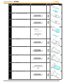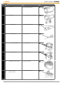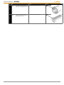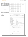
1
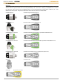
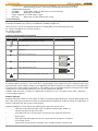
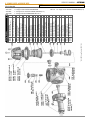
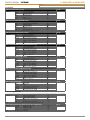
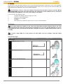
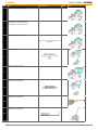
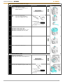
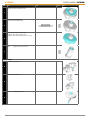
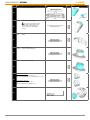
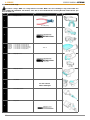
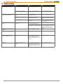
THE ULTIMATE DIVE XSTREAM SERVICE MANUAL SERVICE MANUAL - XSTREAM 1. CONTENTS Table of contents 1. Safety regulations 2. Introduction Markings Service handbook Symbols used throughout the handbook Improvements Product upgrades Information about Xstream Upgrade kits Recommendations 2 3 3 4 4 4 4 5 5 3. Determination of required service 4. Tools and tool order form 5. Spare parts & service kits 6 7 10 Second stages First stage bottom mounted First stage 90 Servicekits Service kits Xstream Upgrade kits Xstream EN144-3 Upgrade Kit 10 11 12 13 13 13 14 6. Service Disassembly Xstream first stage Xstream second stage Cleaning Xstream Deep/Dive Cleaning Xstream Deco/Duration Cleaning for Oxygen Use The cleanroom area and work environment requirements Preparations and Pre-cleaning Cleaning Rinsing and drying in the cleanroom Verification Assembly Xstream first stage Xstream second stage 7. FInal inspection Setting, final inspection Method for regulators cleaned for oxygen use Method for all other regulators 9. Technical data Torque table Product data Conversion tables Work of breathing Breathing curve Performance 10. Oxygen statement 11. Trouble shooting 12. Updates APPENDIX A FAQ(T)’s APPENDIX B Fundamental oxygen risks comprehension The O4 concept APPENDIX C Nomenclature regulator performance 1st stage regulator performance APPENDIX D Cleanroom and oxygen cleaning requirement Check list APPENDIX E Oxygen service authorisation Xstream and Oxygen Service Technician Xstream and Oxygen Service Center 15 15 15 20 24 24 24 24 24 25 25 25 26 26 32 35 35 35 36 38 38 38 39 40 40 40 41 42 43 44 44 45 45 45 46 46 46 47 47 47 48 48 48 48 1 1. SAFETY REGULATIONS SERVICE MANUAL - XSTREAM 1. Safety regulations The instructions in this handbook must be followed in detail step by step. Negligence can cause serious injury or even death. Special warnings are marked with this symbol Xstream Deco and Xstream Duration, are used by the customer with gasses with elevated oxygen content. This requires special procedures while servicing; to clean the regulator and to keep it clean. Negligance to follow the instructions given in this manual introduces a risk for the customer of having a fire which in turn can cause serious injury or even death. Servicing the above-mentioned regulators, shall always be conducted in a clean environment using clean tools, as described in section 6 and in Appendix B. To enhance safety during servicing, the regulators Xstream Deco and Xstream Duration shall be tested using clean air according to specification in 8. There is no need to test regulators in the servicing environment using gasses with > 21% oxygen. Servicing must only be carried out by persons who have been trained and certified by Poseidon. Servicing Xstream Deco and Xstream Duration requires an additional certification as “POSEIDON OXYGEN TECHNICIAN” Only POSEIDON original parts may be used for servicing. Where stated, POSEIDON original tools must be used. 2 2. INTRODUCTION SERVICE MANUAL - XSTREAM 2. Introduction Markings This manual contains servicing and repair instructions and product information for the Poseidon Xstream regulator series. The different Xstream regulator models are most clearly identifed by their color. There is always a possibility that the customer has altered the colors himself, why it is important always to check the permanently marked article number as part of the identification of the product. The pictures below show where to find the article and serial number: 4790-BK / 002-10 Xstream Deep / Xstream Deep (4+1) 4791-BK / 001-47 Xstream Deep90 / Xstream Deep90 (5+2) 4790-GN/ 002-13 /4882-GN Xstream Duration/Xstream Duration(4+1)/Xstream Duration EN 144-3 4791-GN/ 001-87 /4881-GN Xstream Duration90/Xstream Duration90(5+2)/Xstream Duration90 EN 144-3 4790-WE/ 002-16 /4882-WE Xstream Deco/Xstream Deco (4+1)/Xstream Deco EN 144-3 4791-CH Xstream Dive90 4792-YW Xstream Dive Octopus 3 2. INTRODUCTION • • • • • • SERVICE MANUAL - XSTREAM CE 0120 Meets or exceeds requirements in EU Directive 89/686/EEC, Personal Protective Equipment. Manufacturing assessment carried out by notified body SGS Yarsley, ID no. 0120. 4790-BK Model identification E.g 200001 Serial number, 7 digit, 1st digit denotes year of manufacture WP 300bar Working pressure 300 bar Oxygen Approved for use with 99.95% oxygen Nitrox 50% Approved for use with maximum 50% oxygen Service hamdbook This servicing handbook is available for download at the Extranet at http://www.poseidon.se. Make sure you have the latest issue before undertaking any servicing. The handbook is available in English only. Further assistance can be reached between 8:00 am to 4:30 pm (GMT+1) at Poseidon Diving Systems: Ph. +46 (0)31 7342900 ask for “technical assistance” Fax +46 (0)31 7342901 e-mail [email protected] Symbols used throughout the handbook Icon Description Other information Remove old part. Destroy and give back to customer Replace with new part Visually inspect 1 Poseidon grease #1, article no 8515 2 Poseidon grease #2, article no 8507 R Poseidon grease #R, article no 8516 Warning. Negligence can cause serious injury or even death. Improvements Poseidon has made several improvements, all introduced 2003 starting with serial number 310001. Also a 6:th member of the Xstream family is introduced – the Xstream Dive. Correspondingly, article numbers have been changed to reflect these improved models. Article numbers with the two first digits being 45 has been changed to 47. Wherever any text throughout this document refers to article numbers starting with 47, it also applies to the corresponding part/product having an article number starting with 45 i.e. Item number 4790-BK is the new version of old Xstream 4590-BK. Starting in 2006, all Xstream 1st stages are equipped with an adjustment screw cover. Older versions with no adjustment screws should be upgraded. Product upgrades Regulators with serial numbers less than 310001 are subject to a mandatory update programme. To obtain updated replacement parts, order the kit 4826 and submit to Poseidon the serial number of the regulator by sending an email to [email protected] with the serialnumber and date of service clearly marked. Regulators fulfilling this criteria shall have the following parts replaced on its first service: • 4560 replaced by 4760 Seat holder. Seats on regulators numbered after 310001 are different and will not fit older seat holders. • 4577 replaced by 4777 Lower pin-guide. The part has been changed to withstand a greater torque. • 4562 replaced by 4762 Upper centre piece. The part has been changed to correspond to the change of 4577 • 4 4581 Washer. The part has been changed to ease assembly through a more precise fit. SERVICE MANUAL - XSTREAM • 4423 O-ring • 4563 Pin bushing 1.stage Xstream 2. INTRODUCTION Information about Xstream Upgrade kit 4826 4760 Seat holder and 4581 Washer are not critical parts to replace, however old seat holders will not fit new seats and is therefore included in the Update kit Xstream at a special price. 4777 Lower pin-guide and 4762 Upper centre piece should be replaced and is therefore included in the kit at no cost. Information about Xstream 1st stage covers. During 2006, we began manufacturing Xstream DEEP, DEEP90, DURATION, DURATION90 and DECO 1st stages with chrome colored 1st stage covers with an adjustment screw. Starting january 2007, all Xstream 1st stages, regardless of model/version, will have a chrome colored 1st stage cover with an adjustment screw. Information about Xstream Upgrade to cover with adjustment screw. Any Xstream 1st stages that don’t have a cover with an adjustment screw should be upgraded with a cover that has an adjustment screw. This upgrade is not mandatory but recommended. The upgrade is made using the ”Xstream Adjustable kit” (4767-KIT) that contains the following parts: • 1 x 4767-CE Xstream cover • 1 x 4798-CH Adjustment screw • 1 x 4766 Adjustment spring • 1 x 4761 Seat spring All these parts must be replaced when upgrading the 1st stage! Recommendations For regulators with serial numbers less than 310001 we recommend to offer the customer to replace the old type valve housing nut to the improved version with article number 4547. This will significantly reduce the inhalation effort. However if the customer choses to keep his old valve housing nut it is perfectly safe to do so. EN 144-3 Xstream Deco, Xstream Duration and Xstream Duration90 are available also in EN 144-3 configurations, i.e., regulators which comply with the new EN 144-3 standard. See page 3 for correct article numbers. Older Xstream models can be upgraded to comply with the same standard using an EN 144-3 upgrade kit. See Spare Parts lists on page 13 for details. 5 3. DETERMINATION OF REQUIRED SERVICE SERVICE MANUAL - XSTREAM 3. Determination of required service IMPORTANT To be covered by the Poseidon Lifetime Warranty program, all Xstream regulators must be serviced at least once every 24 months. The serviced regulator must also be registered on the Poseidon Extranet (www.poseidon.se). It is always acceptable to do a service or cleaning upon customers request. 6 SERVICE MANUAL - XSTREAM 4. Tools and tool order form 4. TOOLS & ORDER FORM Customer: To service Poseidon regulators there is a number of tools required. Some of the tools are special tools for Xstream and Poseidon and some other tools are standard tools available in most hardware stores. Below you will find a list of all tools needed, with a description of what it is used for. Whenever you need to order a special Poseidon tool it is a good idea to copy this page and use it as an order form. Fill in the number of tools required and fax it to the Poseidon distributor in the country where you are situated. Don’t forget to write the name of your shop in the head of this page. Jetstream Triton Valves Description Xstream Cyklon Item 2297 O-ring remover Used to remove o-rings. o o o o o Open end wrench 6, 13-23 mm Various open end wrenches in millimeters are essential or assembly and dissassembly of various things. o o o o o A specially made, pair of pliers to be used when pulling out locking pins from MPV valves and cutting the mouthpiece strap. o o o o o o o o o o o o o o o o o 4462 Pliers 3460 Regulator test 4830 Ultra Sonic Cleaner 3773 Torque wrench set Picture Used to check or finally adjust the regulator. Used to clean all regulators. Mandatory for Xstream Deco and Duration. Used to set the torque on various parts of the regulator. 1246 Allen key 5 mm Used to unscrew blindplugs and to adjust IP on Xstream. o o o o 2705 Allen key 1,5 mm Used to untighten and tighten the locking screw on Jetstream and Xstream valve tube and stopscrews on most first stages. o o o o o o o o o o o o o o o o o o o o o o o o o o 2150 Plastic band pliers 3605 Combination tool 1 3606 Combination tool 2 3774 Bit holder for yoke 2883 Bit 6 mm, L 30 mm 3397-10 Fixture for first stages 3876 Tool kit for first stage Ord. qty Used to tighten the plastic band around the mouthpiece so that the mouthpiece doesn’t turn around. Used to to screw and unscrew various parts on the first stage and second stages. Used to to screw and unscrew various parts on the first stage and second stages. Used to hold the short bit 2883 when dissassembling and assembling the yoke connection on regulators with fixed yoke. Used when dissassembling and assembling regulators with fixed yoke. Not for G5/8” connections. Used to hold the first stage during dissassembly or assembly. Used to mount all inner details on first stages of type 3720, 3790 and 3880. 7 4. TOOLS & ORDER FORM SERVICE MANUAL - XSTREAM Customer: o o o 2275 Allen key 6 mm Used to untighten the connection stem on all first stages and to adjust IP on first stages. o o o 2893 Screw driver 3,5 mm 3372 Screw driver 5,5 mm (short) 2885 Screw driver 8,5 mm Used for various things; Old Jetstream second stage covers, adjusting Cyklon valve tube, tank valves etc. o o 2705 Adjusting tool Used to adjust the cracking pressure on Jetstream and Xstream. 2894 Test fixture for LP-valve Used to test the leaktightness in water on Jetstream and Xstream servo valve. o o o o Small pair of scissors Not sold by Poseidon o 4592 Oxygen cleaned G5/8” wheel Used as an oxygen clean interface between regulator and testbox while checking and setting. o 4593 Allen key 2,5 mm Used to unscrew and screw the first stage spring cover on Xstream. (3 screws) o 4591 17 mm torque wrench Used to untighten and tighten the connection stem on Xstream first stages. Picture o o 4594 Handle UNF 3/8” Used to hold straight Xstream models when untightening and tightening the connection stem. o 2714 Allen key 3 mm Used to unscrew and screw blindplugs on first stages, type 3580. o 2895 Screw driver Pozi 1 Used to unscrew and screw Jetstream second stage cover. (4 screws) o 2112 Assembly tool Used to mount together the metal cover and the metal housing and at the same time mount the locking ring on all Cyklon second stages. 2299 Drift for LP-valve 3138 Holder for drift 2299 1304 Awl Used to hold together the LP-valve and the spring in the Cyklon second stage when mounting the locking ring. To be placed on a table and with the 2299 drift inserted. Gives you a greater force when holding together the Cyklon LP-valve. o o o Used when removing locking rings. o 8510 Allen key 1,27 mm Used to adjust the cracking pressure on Triton second stages. 3758 Assembly fixture Used when inserting o-rings into Triton second stage swivel. 8 Valves Used to unscrew and screw safety valve on first stages type 3720 and 3790. Triton Jetstream Cyklon Description 3761 Allen key 4 mm Xstream Item o o Ord. qty 4. TOOLS & ORDER FORM SERVICE MANUAL - XSTREAM Customer: Valves Triton Cyklon Used when dismounting Triton LP-valve. Jetstream Description 3761 Dismounting tool Triton Xstream Item Picture Ord. qty o 4461 Drift 4463 Torque wrench head Used as a guide when installing locking pins on MPV valves o To be used when tightening MPV valves on tanks. To be used with a torque wrench. o Articles of consumption 8515 Oxygen grease #1 8507 Oxygen grease #2 8516 Regulator grease 3139 Oil silicone 20 g 4835 Poseidon fine clean ultra Only approved oxygen grease when lubricating oxygen critical parts on the high pressure side. Approved for 300 bar 60oC. o Used when lubricating oxygen critical parts on the low pressure side. Approved for 110 bar 60oC. o o o o o o o o o o o o Used for lubrication of air version regulators. Used for lubrication of air version regulators. 5 litre o 4837 Lint free latex gloves o 4838 Hair net o 9 10 Stop screw Locking strap Mouthpiece AIR O-ring 2nd stage Xstream, EPDM Valve tube Xstream O-ring 2nd stage Xstream, EPDM Servo-valve Xstream 2875 1167 4532 2876-55 4534 1896-55 4545 Valve housing nut, Xstream O-ring 2nd stage Xstream, EPDM 1233-55 Rubber plate Valve insert 3440 2787 LP-valve housing 2857 4547 O-ring Xstream 2nd st., viton O-ring 1145 Housing 4537-BK 2856-59 Sticker Poseidon Xstream Cover Xstream 2nd stage (Deep) Cover Xstream 2nd stage (Deco) Cover Xstream 2nd stage (Duration) Cover Xstream 2nd stage (Octopus) Cover Xstream 2nd stage (Dive) 4538-BK 4538-WE 4538-GN 4538-YW 4538-GY Checkvalve Diaphragm silicone 4533 4531 Diaphragm cover 4536 Qty Second stages 4670-BK 4670-GN 4670-WE 4670-GY 4670-YW 4539 Description Item # 5. SPARE PARTS & SERVICE KITS SERVICE MANUAL - XSTREAM 5. Spare parts & service kits Customer: Second stage Xstream Deep Second stage Xstream Duration Second stage Xstream Deco Second stage Xstream Dive Second stage Xstream Octopus 4807-59 (*/**) 4876-WE (**) 4876-GN (*) 4871 (*/**) * 4884-GN Xstream Duration EN 144-3 ** 4884-WE Xstream Deco EN 144-3 Pin bushing 1.stage Xstream 4563 Blindscrew UNF7/16 O-ring (Deep/Dive) O-ring, viton (Deco/Duration) Blindscrew UNF3/8, 2 pcs O-ring (Deep/Dive) O-ring, EPDM (Deco/Duration) 2680 2918 2918-59 2679 2782 2782-55 4798-BK Adjustment screw, black 4798-CE Adjustment screw, chrome Barrier 1.stage Xstream black Barrier 1.stage Xstream white Barrier 1.stage Xstream green Cover Xstream 1st stage, black Cover Xstream 1st stage, chrome Screw cover M3x10 Xstream, 3 pcs Lower pin guide Xstream 4777 Adjust. spring 1.stage Xstream Valve seat spring Xstream 4761 4570-BK 4570-WE 4570-GN 4767-BK 4767-CE 4568 Valve seat holder Xstream 4760 Pressure plate 1.stage Xstream Zytel valve seat Xstream 4758 4766 O-ring (Deep) O-ring, viton (Deco/Duration) 4557 4557-59 Roll.diaphragm 1.stage Xstream Ball 1.stage Xstream 4556 4565 Spring for ball Xstream 4555 Actuating pin, Xstream Housing 1.stage Xstream 4774 4564 Wheel G5/8” Xstream, black Wheel G5/8” Xstream, white Wheel G5/8” Xstream, green Wheel Xstream, green (*) Wheel Xstream, white (**) 4576-BK 4576-WE 4576-GN 4876-GN 4876-WE 4559 Stainl. washer 1.stage Xstream 4581 O-ring Cup type filter Xstream 4572 1st stage G 5/8” Xstream DEEP 1st stage G 5/8” Xstream DURATION 1st stage G 5/8” Xstream DECO 1st stage Xstream DURATION EN 144-3 1st stage Xstream DECO EN 144-3 Upper pin guide Xstream Conn. stem 1.stage Xstream Conn. stem 1.stage Xstream (*/**) 4571 4871 Qty 4780-BK 4780-GN 4780-WE 4884-GN 4884-WE 4762 O-ring (Deep) O-ring, viton (Deco/Duration) O-ring, viton (*/**) 1007 1007-59 4807-59 First stage bottom mounted 4423 Description Item # SERVICE MANUAL - XSTREAM 5. SPARE PARTS & SERVICE KITS Customer: 002-09 1st stage G 5/8” Xstream DEEP (4+1) 002-12 1st stage G 5/8” Xstream DURATION (4+1) 002-15 1st stage G 5/8” Xstream DECO (4+1) 11 12 4876-GN (*) (deep90/dive90) (duration90) (deep90/dive90) (duration90) * 4883-GN Xstream Duration90 EN 144-3 Valve seat spring Xstream Lower pin guide Xstream Pin bushing 1.stage Xstream O-ring Upper pin guide Xstream Actuating pin, Xstream Roll.diaphragm 1.stage Xstream Pressure plate 1.stage Xstream Adjust. spring 1.stage Xstream Barrier 1.stage Xstream black Barrier 1.stage Xstream green Cover Xstream 1st stage, black Cover Xstream 1st stage, chrome Screw cover M3x10 Xstream, 3 pcs 4761 4777 4563 4423 4762 4559 4564 4565 4766 4570-BK 4570-GN 4767-BK 4767-CE 4568 2918 2918-59 2679 2782 2782-55 4576-BK 4576-GN 4876-GN O-ring (Deep90/Dive90) O-ring, viton (Duration90) Blindscrew UNF3/8, 3 pcs O-ring (Deep90/Dive90) O-ring, EPDM (Duration90) Wheel G5/8” Xstream, black Wheel G5/8” Xstream, green Wheel Xstream, green (Duration90 EN 144-3) 4798-BK Adjustment screw, black 4798-CE Adjustment screw, chrome 2680 Blindscrew UNF7/16 Valve seat holder Xstream 4760 001-85 (deep90/dive90 (duration90) Ball 1.stage Xstream 4557 O-ring (Deep90/Dive90) 4557-59 O-ring, viton (Duration90) 4758 Zytel valve seat Xstream 4556 1st stage G 5/8”Xstream DEEP90 1st stage G 5/8”Xstream DURATION90 1 st stage G 5/8” Xstream DIVE90, DEEP90 (5+2) 1 st stage Xstream DURATION90 EN 144-3 4878 (*) 4807-59 (*) (deep90/dive90) (duration90) O-ring (Deep90/Dive90) O-ring (Duration90) Line protector Xstream, black Line protector Xstream, green Housing 1.stage 90 Xstream 2918 2918-59 4579-BK 4579-GN 4754 Qty First stage 90 (deep90/dive90) (duration90) (deep90/duration90) (dive90) (deep90/dive90) (duration90) Cup type filter long Xstream 90 4552 4754-5IP Housing 1.stage Dive 90, Deep 90, Duration 90 Xstream (5+2 versions) 4555 Spring for ball Xstream Conn. stem 1.stage 90 Xstream Conn. stem 1.stage Duration90 EN 144-3 4778 4878 1007 O-ring (Deep90/Dive90) 1007-59 O-ring, viton (Duration90) 4807-59 O-ring. viton (Duration90 EN 144-3) Description 4751-BK 4751-GN 4752-BK 4883-GN (deep90/dive90 (duration90) (deep90/duration90 (dive90) (deep90/duration90 (dive90) Item # 5. SPARE PARTS & SERVICE KITS Customer: SERVICE MANUAL - XSTREAM 1st stage G 5/8” Xstream DURATION90 (5+2) SERVICE MANUAL - XSTREAM 5. SPARE PARTS & SERVICE KITS Customer: Servicekits 4821 Servicekit Xstream Deep 1:st stage Included: 4758 4572 2782 2918 4557 4423 1007 Zytel valve seat Xstream Cup type filter Xstream O-ring (Deep/Dive) O-ring (Deep/Dive) O-ring (Deep/Dive) O-ring O-ring (Deep/Dive) Ord. qty 1 pc 1 pc 3 pcs 2 pcs 1 pc 1 pc 1 pc 4822 Servicekit Xstream Deep90, Dive90 1:st stage Included Note: 4758 Zytel valve seat Xstream 4552 Cup type filter long Xstream 90 2782 O-ring (Deep/Dive) 2918 O-ring (Deep/Dive) 4557 O-ring (Deep/Dive) 4423 O-ring 1007 O-ring (Deep/Dive) Servicing a Deep90 leaves you 2 2782 and 1 2918. Ord. qty 1 pc 1 pc 5 pcs 3 pcs 1 pc 1 pc 1 pc 4823 Servicekit Xstream Duration, Deco 1:st stage Included: 4758 4572 4563 2782-55 2918-59 4557-59 4423 1007-59 Zytel valve seat Xstream Cup type filter Xstream Pin bushing 1.stage Xstream O-ring, EPDM (Deco/Duration) O-ring, viton (Deco/Duration) O-ring, viton (Deco/Duration) O-ring O-ring, viton (Deco/Duration) Ord. qty 1 pc 1 pc 1 pc 3 pcs 2 pcs 1 pc 1 pc 1 pc 4827 Servicekit Xstream Duration EN 144-3, Deco EN 144-3 1:st stage Included: 4758 4572 4563 2782-55 2918-59 4557-59 4423 4807-59 Zytel valve seat Xstream Cup type filter Xstream Pin bushing 1.stage Xstream O-ring, EPDM (Deco/Duration) O-ring, viton (Deco/Duration) O-ring, viton (Deco/Duration) O-ring O-ring, viton EN 144-3 Ord. qty 1 pc 1 pc 1 pc 3 pcs 2 pcs 1 pc 1 pc 1 pc 4824 Servicekit Xstream Duration90 1:st stage Included: 4758 4552 4563 2782-55 2918-59 4557-59 4423 1007-59 Zytel valve seat Xstream Cup type filter long Xstream 90 Pin bushing 1.stage Xstream O-ring, EPDM (Deco/Duration) O-ring, viton (Deco/Duration) O-ring, viton (Deco/Duration) O-ring O-ring, viton (Deco/Duration) Ord. qty 1 pc 1 pc 1 pc 3 pcs 2 pcs 1 pc 1 pc 1 pc 4828 Servicekit Xstream Duration90 EN 144-3 1:st stage Included: 4758 4552 4563 2782-55 2918-59 4557-59 4423 4807-59 Ord. qty Zytel valve seat Xstream Cup type filter long Xstream 90 Pin bushing 1.stage Xstream O-ring, EPDM (Deco/Duration) O-ring, viton (Deco/Duration) O-ring, viton (Deco/Duration) O-ring O-ring, viton EN 144-3 1 pc 1 pc 1 pc 3 pcs 2 pcs 1 pc 1 pc 1 pc Locking strap Rubber plate O-ring O-ring 2nd stage Xstream, EPDM O-ring Xstream 2nd st., viton O-ring Xstream 2nd st, EPDM O-ring Xstream 2nd st , EPDM 1 pc 1 pc 1 pc 1 pc 1 pc 1 pc 1 pc 4825 Servicekit Xstream 2nd stage Included: 1167 2787 1145 1233-55 2856-59 2876-55 1896-55 Ord qty Xstream Upgrade Kit 4826 Xstream upgrade kit for models below s/n 310001 Included: Note: 4760 Valve seat holder Xstream 4777 Lower pin guide Xstream 4762 Upper pin guide Xstream 4581 Stainl. washer 1.stage Xstream 4423 O-ring 4563 Pin bushing 1st stage Xstream Servicing a Xstream 90 model leaves you 1 pcs washer 4581. 4767-KIT Xstream adjustment kit for Xstream 1st stages with no adjustmentscrew Included: Note: 4767-CE Xstream 1st stage cover 4798-CH Adjustment screw 4766 Adjustment spring 4761 Seat spring Fits all Xstream 1st stages 1 pc 1 pc 1 pc 1 pc 1 pc 1 pc 1 pc 1 pc 1 pc 1 pc Ord qty Ord qty 13 SERVICE MANUAL - XSTREAM 5. SPARE PARTS & SERVICE KITS Xstream EN 144-3 upgrade kits 4880-GN Xstream Duration EN 144-3 kit Included: 4871 4807-59 4876-GN 4572 Connection stem Xstream Duration/Deco EN 144-3 O-ring EN 144-3 Wheel Xstream Duration EN 144-3 Cup type filter Xstream 4851-GN Xstream Duration90 EN 14-3 kit Included: 4878 4807-59 4876-GN 4552 2918-59 4880-WE Xstream Deco EN 144-3 kit Included: 14 4871 4807-59 4876-WE 4572 Connection stem Xstream Duration90 EN 144-3 O-ring EN 144-3 Wheel Xstream Duration EN 144-3 Cup type filter long Xstream 90 O-ring 1 pc 1 pc 1 pc 1 pc 1 pc 1 pc 1 pc 1 pc 1 pc Connection stem Xstream Duration/Deco EN 144-3 O-ring EN 144-3 Wheel Xstream Deco EN 144-3 Cup type filter Xstream 1 pc 1 pc 1 pc 1 pc Ord qty Ord qty Ord qty SERVICE MANUAL - XSTREAM 6. SERVICE 6. Service The parts that needs to be replaced during a service are described in the Spare parts & Servicekits section of this handbook. Make sure that you have servicekits for the corresponding model and that you have all special tools required available. The tools required are described in the Tools section of this hand book. For instructions on how to service the regulator follow the instruction below until you reach the ”GO TO FINAL INSPECTION” text at the end of the instruction. The instructions in this handbook must be followed in detail step by step. Negligence can cause serious injury or even death. A service includes the following 5 steps: 1. Complete disassembly of the first stage and second. 2. Inspection of disassembled parts. 3. Cleaning prior to assembly. 4. Assembly. 5. Final inspection and adjustment, please refer to section 7 of this handbook. Disassembly Do not disassemble the regulator in the clean room environment. All parts shall be taken to the clean room environment after inspection and after the pre-cleaning process if such is needed. Otherwise you risk to contaminate the clean room environment. New parts should be stored in it’s original packing until it is time for assembly. To remove o-rings, ONLY use o-ring remover tool 2297. Make sure not to damage o-ring and sealing surfaces!! Xstream first stage Step Parts Tools/Instructions Replace Picture All first stages 2680 Blindscrew UNF 7/16” 1 or 2 pcs 2679 Blindscrew UNF 3/8” 2, 3 or 5 pcs 1 4568 Screw M3x10 Xstream 3 pcs 2 4767-BK Cover Xstream first stage black 4767-CE Cover Xstream first stage chrome 3 4766 Press. spring 1.stage Xstream 4 6 15 SERVICE MANUAL - XSTREAM 6. SERVICE Step Parts Tools/Instructions 4565 Pressure plate 1.stage Xstream 5 4570-BK Barrier 1.stage Xstream black 4570-WE Barrier 1.stage Xstream white 4570-GN Barrier 1.stage Xstream green 6 4564 Roll. diaphragm 1.stage Xstream Only use fingers. Tools may puncture the diaphragm 7 Pin guide assembly 8 4761 Valve seat spring Xstream 9 4760 Valve seat holder Xstream 4758 Zytel valve seat Xstream 10a 4760 Valve seat holder Xstream 4758 Zytel valve seat Xstream 10b 4760 Valve seat holder Xstream 4758 Zytel valve seat Xstream 10c 16 Replace Picture SERVICE MANUAL - XSTREAM 6. SERVICE Only for Xstream bottom mounted first stages Step Parts Tools/Instructions 1007 1007-59 4807-59 O-ring (Deep) O-ring, viton (Deco/Duration) O-ring, viton EN 144-3 (Deco EN 1443/Duration EN 144-3) 4571 4871 Conn. stem 1.stage Xstream Conn. stem 1.stage Xstream EN 1443 (Deco EN 144-3/Duration EN 144-3) 4576-BK 4576-WE 4576-GN 4876-GN 4876-WE Wheel G5/8” Xstream, black Wheel G5/8” Xstream, white Wheel G5/8” Xstream, green Wheel Xstream Duration EN 144-3, green Wheel Xstream Deco EN 144-3, white 4572 Cup type filter Xstream 4581 Stainl. washer 1.stage Xstream Replace Picture 11 12 13 14 15 Only for Xstream 90 first stages 1007 O-ring (Deep90/Dive90) 1007 59 O-ring viton (Duration90) 4807-59 O-ring, viton EN 144-3 (Duration90 EN 144-3) 16 4778 Conn. stem 1.stage 90 Xstream 4878 Conn. stem 1.stage EN 144-3 (Duration90 EN 144-3) 17 17 SERVICE MANUAL - XSTREAM 6. SERVICE Step Parts Tools 4576-BK Line protector Xstream, black 4576-GN Line protector Xstream, green 18 2918 O-ring (Deep90/Dive90) 2918-59 O-ring Viton (Duration90) 19 4576-BK Wheel G5/8” Xstream, black 4576-GN Wheel G5/8” Xstream, green 4876-GN Wheel Xstream Duration EN 144-3, green 20 4552 Cup type filter long Xstream 90 21 All first stages 4556 Ball 1.stage Xstream 22 4555 Spring for ball Xstream 23 4559 24 18 Actuating pin, Xstream Replace Picture SERVICE MANUAL - XSTREAM Step Parts 4777 6. SERVICE Tools Replace Picture Lower pin guide Xstream 25 6 mm 4563 Pin bushing 1.stage Xstream Do not pull out nor replace the Pin bushing while servicing Dive or Deep models. This should only be done while servicing Deco and Duration models. 26 4423 O-ring 4557 4557-59 O-ring (Deep/Dive) O-ring, viton (Deco/Duration) 4758 Zytel valve seat Xstream Screw in M3 screw 4568 in the pin bushing and pull out. 27 28 29 On blindscrew UNF 3/8” 2782 O-ring Deep 2 or 3 pcs, Dive 5 pcs 2782 55 O-ring EPDM Deco 2 or 3 pcs Duration 2 or 3 pcs 30 On blindscrew UNF 7/16” 2918 O-ring Deep 1 pcs, Dive 2 pcs 2918 59 O-ring Viton Deco/Duration 1 pcs 4798 Adjusting screw 31 19 SERVICE MANUAL - XSTREAM 6. SERVICE Xstream second stage To remove o-rings, ONLY use o-ring remover tool 2297. Make sure not to damage o-ring surfaces!!Do not disassemble the exhalation check-valve, since this is not included in the servicing kit and can be hard to put back if taken out. Step Parts 4532 Tools Mouthpiece AIR Replace 4462 Pliers 1 For cutting strap 2 3 4538-BK 4538-WE 4538-GN 4538-YW 4538-GY Cover Xstream 2nd stage (Deep) Cover Xstream 2nd stage (Deco) Cover Xstream 2nd stage (Duration) Cover Xstream 2nd stage (Octopus) Cover Xstream 2nd stage (Dive) 4536 Diaphragm cover Twist off. 4 Snap connection. 4533 Diaphragm silicone 4531 Checkvalve 5 6 Do not remove! Unless damaged 4545 Servo-valve Xstream 2875 Stop screw 7 8 20 Picture SERVICE MANUAL - XSTREAM Step Parts 6. SERVICE Tools 4534 Valve tube Xstream 1896-55 O-ring 2nd stage Xstream, EPDM 2876-55 O-ring 2nd stage Xstream, EPDM 4547 Vavle housing nut, Xstream 2787 Rubber plate 1233-55 O-ring 2nd stage Xstream, EPDM 1145 O-ring 3440 Valve insert 2856-59 O-ring Xstream 2nd st., viton Replace Picture 9 10 11 12 13 14 15 16 17 21 SERVICE MANUAL - XSTREAM 6. SERVICE Inspections Step Parts Inspect Picture 3440 Valve insert 1. Ensure no circular cuts on bladder surface. 2. Check O-ring sealing surface 4531 Checkvalve 1. Check for damages on check valve edge 4534 Valve tube Xstream 1. Check O-ring sealing surfaces 4545 Servo-valve Xstream 1. Make sure not bent 4754 Housing 1.stage 90 Xstream 1. Check sealing surfaces 1 2 3 4 5 4774 Housing 1.stage Xstream 1. Check sealing surfaces 4564 Roll.diaphragm 1.stage Xstream 1. Check for wear and tear 2680 Blindscrew UNF7/16 1. Check O-ring sealing surfaces 2679 Blindscrew UNF3/8, 6 7 8 22 SERVICE MANUAL - XSTREAM Step Parts 6. SERVICE Inspect 4571 4871 Conn. stem 1.stage Xstream 1. Check O-ring sealing surfaces Conn. stem 1.stage Xstream EN 1443 (Deco EN 144-3/Duration EN 144-3) 4778 4878 Conn. stem 1.stage 90 Xstream Conn. stem 1.stage Xstream EN 1443 (Duration90 EN 144-3) Picture 9 1. Check O-ring sealing surfaces 10 23 6. SERVICE SERVICE MANUAL - XSTREAM Cleaning Xstream Deep/Dive Cleaning Make absolutely sure Hydrochloric acid is NOT poured into the ultra-sonic cleaner. It would then destroy the ultra-sonic cleaner and the parts attempted to be cleaned. If corrosion or salt deposits occurs on metallic parts, immerse part in concentrated Hempocid* or 15% Hydrochloric acid for about 10 minutes. Then rinse them thoroughly in fresh water and blow them dry with air. The synthetic parts must not be treated with solvents and must only be cleaned with fresh water. *Hempocid=Acid Liquid detergent containing phosphoric acid (5-10%) and bactericide for disinfectant cleaning Xstream Deco/Duration Cleaning for Oxygen Use The process of cleaning for oxygen use and the information given herein shall be strictly adhered to. Only then can Poseidon guarantee the regulator will be cleaned to a cleanliness level which is acceptable for its intended use. This process has been verified to produce hydrocarbon residual levels less than 50mg/m2 and a particulate level less than Cleaning Test Level 100 (ASTM G 93 Spec.) As an alternative, oxygen servicing procedures can be carried out in accordance with other herein listed organizations standard procedures and requirements. However, the use of cleaning agents, the order of the operating sequences and the time to treat parts during ultra sonic cleaning as specified in this manual must be adhered to. Wherever there is a conflict between the procedures and set of requirements, unless the other procedure represents a greater requirement for cleanliness, this manual takes precedence. Some methods, equipment, and detergents which are not mentioned in this manual can have a harmful or unknown effect on materials, such as e.g. ozone cleaning systems, strong acids etc. and shall therefore be discarded. The other standard procedures that can be used given the limitations above are: EAN and Oxygen Servicing Procedures, Fourth Edition (ANDI) IANTD Gas Blender & Service Technician Program, First Edition, August 1999 MIL-STD-1330D (SH) of the 20 September 1996 The safety of your customer and yourself depends on you carefully and strictly following these instructions. Negligence in any step can cause serious injury or even death. You must be certified by Poseidon as oxygen technician to undertake this procedure. Keep hands and tools clean and free from grease, except for what is required and stated in this manual. Use protective clothing to prevent dust, fingerprints, hair, and particles to contaminate. Use only dedicated and cleaned tools. Ensure your oxygen handling is in conjunction with national laws. Ensure no foreign contaminants, such as e.g. liquids, grease, particulate, dust, and mist can enter into the cleanroom area. The cleanroom area and work environment requirements The cleanroom area and work environment should be setup according to minimum demands listed in Appendix D. A cleanroom area and work environment audit should be performed once a year either by a service technician or by a from Poseidon appointed auditor. The checklist in Appendix D should be used to make sure that all criterias are fulfilled. For detailed instructions on how to perform and audit please refer to Appendix D. Preparations and Pre-cleaning 1. These preparations and the pre-cleaning shall NOT be conducted in the clean room, since it may then contaminate the clean room. If any part is visibly contaminated, it shall be pre-cleaned, including the parts listed below which shall not be ultra sonic cleaned. Only undertake the pre-cleaning if you are sure you can move on to the cleaning stage immediately after. If the parts dry between the two stages of operation, undesirable deposits can be left on part surfaces. 2. 3. 24 SERVICE MANUAL - XSTREAM 4. Bag the parts below in a plastic bag for later assembly. These parts shall not be ultra sonic cleaned. 5. Use IPA and a toothbrush to agitate away all visible contaminants. Rinse part(s) in municipal running water until all visible soil, particulate and cleaning agent is removed. When using IPA make sure you have sufficient ventilation. Please refer to the safety instructions of the IPA. Use air of any quality to blow dry. 6. 6. SERVICE THE PROCESS BELOW SHOULD BE PERFORMED OUTSIDE THE CLEANROOM AREA Cleaning 1. 2. 3. 4. 5. 6. 7. 8. Wash your hands before this cleaning process. Always ensure the UltraSonic cleaner is absolutely clean inside Fill the UlraSonic cleaner with Poseidon FineClean Ultra and water in the ratio 1:5. Let the UltraSonic cleaner reach its working temperature 60-70°C . Place all parts in the basket. The parts shall be placed so that no air is trapped inside. Turn the part a few times under the solution until no bubbles are coming from it. Ultra Sonic cleaning agitates away contaminants, why it is important to finally place the part so that contaminants can drop out freely, i.e. open holes pointing down. (as shown in the figure). Ensure parts are not contacting each other, since that may reduce the cleaning effectiveness. Immerse and ultra sonic clean the parts for 20-25 minutes 3440, rolling diaphragm and the servovalve shall only be cleaned for 10 minutes Bring all parts needed to assemble the complete regulator to the clean room. Keep the bagged 2nd stage parts and the service kit parts in their bags until immediately before assembly. THE PROCESS BELOW SHOULD BE PERFORMED INSIDE THE CLEANROOM AREA Rinsing and drying in the cleanroom From this stage and through the assembly stages cleanroom clothing including gloves shall be used. Pick up each part from the basket and rinse carefully under running water at least 30 seconds per part, or; Rinse in two stages keeping the parts in the basket. Immerse the basket with the parts in another container of at least 3 litres of clean water and agitate for at least 5 minutes. Then replace the rinsing water with new clean water (ideally deionised, distilled, and filtrated water), and rinse for another 5 minutes. Ensure all cavities are carefully rinsed. It is the internal rinsing which is the most important! Dry the parts by using a cleaned blowgun and clean air, and blow dry each part carefully. Verification White light All parts shall be observed for the absence of contaminations under strong white light and for the accumulations of lint fibres. This method will detect particulate matter in excess of 50 microns and other contaminations in relatively large amounts. The part being examined must be recleaned if any contamination is detected using this method. You shall have access to, and use if found necessary, a magnifying glass or a microscope with at least x10 magnification. Ultraviolet light (Black light) Examine all parts in darkness using an ultraviolet light of between 3200 to 3800 Angstrom wavelength. If a bluish-white fluorescent blotch, smear, smudge, or film is present, the pert must be recleaned. Ultraviolet light inspection will help to verify that cleaned surfaces are free from any hydrocarbon fluorescence. If parts cannot be used immediately for assembly, pack in clean plastic bags to avoid parts from being recontaminated. 25 SERVICE MANUAL - XSTREAM 6. SERVICE Assembly Lubricants shall be used sparingly. Excessive quantities of lubricant can trap particulate and other contaminants developing apotential fire hazard. Parts marked with the symbol are parts that must be replaced at every service. New parts should be stored in it’s original packing until it is time for assembly. Xstream first stage Step Parts Tools/Instructions Replace Picture All first stages 4758 Zytel valve seat Xstream 1 4557-59 O-ring, viton (Deco/Duration) 1 Deco/Duration 2a 4557 O-ring (Deep/Dive) 2 Deep/Dive 2b 4423 O-ring Use bushing 4563 to install o-ring 3 4763 Pin bushing 1.stage Xstream 4 Make sure fully to the bottom 4777 Lower pin guide Xstream 5 3 +/- 1 Nm Refer to section 9 for other units. 26 SERVICE MANUAL - XSTREAM Step Parts 4759 6. SERVICE Tools/Instructions Replace 6 Picture 2 Actuating pin, Xstream Lubricate pin at top section only. Leaving lower end dry. Wipe off excessive grease under the hat. 4798 Adjusting screw 7 On blindscrew UNF 3/8” 2782 55 O-ring EPDM Deco 2 or 3 pcs Duration 2 or 3 pcs 8a On blindscrew UNF 7/16” 2918 59 O-ring Viton Deco/Duration 1 pcs 1 Deco/Duration 2 On blindscrew UNF 3/8” 2782 O-ring Deep 2 or 3 pcs, Dive 5 pcs 8b On blindscrew UNF 7/16” 2918 O-ring Deep 1 pcs, Dive 2 pcs Deep/Dive Xstream 90 first stage 4552 Cup type filter long Xstream 90 9 4576-BK Wheel G5/8” Xstream, black 4576-GN Wheel G5/8” Xstream, green 4876-GN Wheel Xstream, green (Duration90 EN144-3) 10 2918-59 O-ring Viton (Duration90) 1 Duration 11a 2918 O-ring (Deep90/Dive90) 2 Deep/Dive 11b 27 SERVICE MANUAL - XSTREAM 6. SERVICE Step Parts Tools/Instructions Replace Picture 4576-BK Line protector Xstream, black 4576-GN Line protector Xstream, green 12 4771 Conn. stem 1.stage 90 Xstream 4878 Conn. stem 1.stage Xstream EN 144-3 (Duration90 EN 144-3) 13 Ensure line protector is correctly positioned, with one slot facing to the bottom of the housing Torque setting 30 Nm Refer to section 9 for other units. 1007 59 O-ring viton (Duration90) 4807-59 O-ring viton EN 144-3 (Duration90 EN 144-3) 14a 1007 O-ring viton (Deep/Dive) 14b Go to step 21 Xstream bottom mounted first stage 4581 Stainl. washer 1.stage Xstream 4572 Cup type filter Xstream 15 1 Deco/Duration 16 4572 2 Cup type filter Xstream Deep/Dive 17 18 4576-BK 4576-WE 4576-GN 4876-GN 4876-WE 28 Wheel G5/8” Xstream, black Wheel G5/8” Xstream, white Wheel G5/8” Xstream, green Wheel Xstream, green (Duration EN144-3) Wheel Xstream, white (Deco EN144-3) SERVICE MANUAL - XSTREAM Step Parts 4571 4871 6. SERVICE Tools/Instructions Replace Picture Conn. stem 1.stage Xstream Conn. stem 1.stage Xstream EN 1443 (Duration EN 144-3/Deco EN 144-3) 19 Use handle to hold first stage. Torque setting 30 Nm Refer to section 9 for other units. 1007-59 4807-59 O-ring, viton (Deco/Duration) O-ring, viton EN 144-3 (Deco EN 1443/Duration EN 144-3) 20a 1007 O-ring (Deep/Dive) 20b All first stages 4555 Spring for ball Xstream 21 Wider end facing upwards, towards the ball. 4556 Ball 1.stage Xstream 22 4760 Valve seat holder Xstream 4758 Zytel valve seat Xstream 23 4761 Valve seat spring Xstream 24 Pin guide assembly Deco/Duration 1 25a 6 +/- 1 Nm Refer to section 9 for other units. 29 SERVICE MANUAL - XSTREAM 6. SERVICE Step Parts Pin guide assembly Tools/Instructions Replace Deep/Dive Picture 2 25b 6 +/- 1 Nm Refer to section 9 for other units. 4564 Roll. diaphragm 1.stage Xstream 26 4570-BK Barrier 1.stage Xstream black 4570-WE Barrier 1.stage Xstream white 4570-GN Barrier 1.stage Xstream green 27 You should see the marking ”This side up” on the barrier. 4565 Pressure plate 1.stage Xstream 28 54766 Adj. spring 1.stage Xstream 29 6 4567-BK Cover Xstream first stage, black 4567-CE Cover Xstream first stage, chrome 30 4568 Screw cover M3x10 Xstream 3 pcs Deco/Duration 2 31a 6 +/- 1 Nm Refer to section 8 for other units. 4568 Screw cover M3x10 Xstream 3 pcs Deep/Dive 31b 6 +/- 1 Nm Refer to section 9 for other units. 30 R SERVICE MANUAL - XSTREAM Step Parts 2680 Blindscrew UNF 7/16” 1 or 2 pcs 2679 Blindscrew UNF 3/8” 2, 3 or 5 pcs 6. SERVICE Tools/Instructions Replace Picture 32 31 SERVICE MANUAL - XSTREAM 6. SERVICE Parts marked with the symbol are parts that must be replace at every service. New parts should be stored in it’s original packing until it is time for assembly. Xstream second stage Step Parts 2856-59 Tools/Instructions O-ring Xstream 2nd st., viton Replace Picture 2 Deco/Duration 1a 2856-59 O-ring Xstream 2nd st., viton Deep/Dive R 1b 3440 Valve insert 1145 O-ring 2 2 Deco/Duration 3a 1145 R O-ring Deep/Dive 3b 1233-55 2 O-ring 2nd stage Xstream, EPDM Deco/Duration 4a 1233-55 R O-ring 2nd stage Xstream, EPDM Deep/Dive 4b 32 SERVICE MANUAL - XSTREAM Step Parts 6. SERVICE Tools/Instructions 4547 Vavle housing nut, Xstream 2876-55 O-ring 2nd stage Xstream, EPDM Replace Picture 5 3 +/- 1 Nm 2 Deco/Duration 6a 2876-55 R O-ring 2nd stage Xstream, EPDM Deep/Dive 6a 1896-55 2 O-ring 2nd stage Xstream, EPDM Deco/Duration 7a 1896-55 R O-ring 2nd stage Xstream, EPDM Deep/Dive 7b 4534 Valve tube Xstream 2787 Rubber plate 8 9 2875 Stop screw 10 33 SERVICE MANUAL - XSTREAM 6. SERVICE Step Parts 4545 Tools/Instructions Replace Servo-valve Xstream 11 Firm by hand 4531 Checkvalve ONLY IF REPLACED 12 4533 Diaphragm silicone 4536 Diaphragm cover 4538-BK 4538-WE 4538-GN 4538-YW 4538-GY Cover Xstream 2nd stage (Deep) Cover Xstream 2nd stage (Deco) Cover Xstream 2nd stage (Duration) Cover Xstream 2nd stage (Octopus) Cover Xstream 2nd stage (Dive) 13 13 14 15 Install valve tube 4532 Mouthpiece AIR 16 GO TO FINAL INSPECTION 34 Picture SERVICE MANUAL - XSTREAM 7. FINAL INSPECTION 7. FInal inspection Setting, final inspection Property 1st stage Setting SI units Setting common units Setting US units P1 P2 P3 P4@p1, P4@p3. P5 i R Q Internal leaktightness 30 MPa >750 kPa 2 MPa 800 – 1100 kPa (unadjustable) 840 – 860 kPa (adjustable) >750 kPa +/- 110 kPa max 100 kPa 0.12 m3/h 300 bar > 7.5 bar 20 bar 8bar - 11bar (unadjustable) 8.4bar - 8.6bar (adjustable) > 7.5 bar +/- 1.1 bar max 1 bar 2 L/min 12 ml/h* 4351 psi >109 psi 290 psi 116 - 160 psi (unadjustable) 122 - 125 psi (adjustable) >109 psi +/-16 psi max 15 psi 0.07 ft3/min * Corresponds to a pressure climb of 0,01 bar/min for a regulator with a 70 cm hose. Property 2nd stage CP (cracking pressure) Setting SI units Setting common units Setting US units -274 Pa to - 392 Pa -28 to -40 mm.w.c -1.1 to -1.6 inch of water Method for regulators cleaned for oxygen use Unless you do have access to an oxygen cleaned test station, you must ensure you do not re-contamine the regulator when doing the final adjustment and setting. Re-contamination can be caused by e.g. contaminated test gas, contaminated gauge fittings, contaminated regulator connection, contaminated test station pipings etc. FIRST STAGE SETTING: 1) Slowly open cylinder valve 2) Check IP 3) Close valve 4) Purge 5) Adjust IP (1/2 turn = 1.5 bar) 6) Open valve 7) Check IP (loop to 3) 8) Close valve 9) Purge 2. 7. 4. 5. 6. 3. 8. 1. 9. SECOND STAGE SETTING: 1) Open valve 2) Check cracking pressure 3) Adjust cracking pressure 2. 4) Close valve 5) Purge 5. 1. 4. 3. 35 SERVICE MANUAL - XSTREAM 7. FINAL INSPECTION Method for all other regulators SYSTEM CHECK: 1) Open left valve 20 bar 2) Close left valve 20 bar 3) Purge 1. 2. 3. FIRST STAGE SETTING: 1) Open right valve HP (200-300bar) 2) Purge 3) Check IP (go to 9 if OK) 4) Close right valve 3. 8. 12. 6. 5) Purge 6) Adjust IP (1/2 turn = 1.5 bar) 7) Open right valve 8) Check IP (loop to 4) 11. 13. 1. 4. 7. 9. 9) Close right valve 10) Purge 11) Open left valve (20 bar) 2. 5. 10. 14. 12) Check IP 13) Close left valve 14) Purge SECOND STAGE SETTING: 1) Open either left or right valve, whichever gave the lowest IP 2) Check cracking pressure 2. 3) Adjust cracking pressure 4) Close valve 5) Purge 1. 4. 1. 4. 3. 5. 36 SERVICE MANUAL - XSTREAM 7. FINAL INSPECTION ADJUST THE 2ND STAGE TO 28-40 MM.W.C. 1) Hold the mouthpiece-part of the cracking pressure gauge tight to the outlet of the 2nd stage 2) Take a few rather slow and long inhalations from the m o u t h p i e c e part and simultaneously check the pressure gauge needle. It shall during inhalation reach a maximum of 28-40 mm.w.c, and at the end of the inhalation decrease again. If the reading is too high, unscrew the stopscrew as shown in the illustration below-right. Screw the valve tube away from the diaphragm as shown in illustration to the right. If the reading is too low, screw the valve tube towards the diaphragm. Once the reading is correct tighten the stopscrew and then doublecheck the reading. 3) Alternatively: immerse the 2nd stage as shown in the illustration. A sizzling sound from the servo-valve opening shall occur within the two markings. TIP! Some divers like the setting extremely light, and some prefer a higher cracking pressure. Ask your customer. Technically, Xstream can be adjusted from 0 mm.w.c to > 100 mm.w.c. The risk for a free flow increases with decreasing cracking pressure. Below 25 mm.w.c in a certain attitude (exhalation diaphragm the shallowest and inhalation diaphragm the deepest), the regulator inhalation valve will stay permanently open, bubbleing. Above 40 mm.w.c the breath doesn’t feel good. 37 SERVICE MANUAL - XSTREAM 9. TECHNICAL DATA 9. Technical data Torque table Part subject to torque wrench use Blind screws First stage connection stem to body Centre piece Lower centre piece 2nd stage Hose to 1st stage Cover screws 1st stage Valve house nut Servo valve Hose to 2:nd stage Newton Meter Nm Inch Pounds Inch-lbs Foot Pounds Ft-lbs Kilogram Meter Kgm 6 +/- 1 53 +/- 9 4.4 +/- 0.7 0.6 +/- 0.1 20 +/- 2 177 +/- 18 17 +/-2 2 +/- 0.2 6 +/- 1 53 +/- 9 4.4 +/- 0.7 0.6 +/- 0.1 3 +/- 1 27 +/- 5 2.2 +/- 0.4 0.3 +/- 0.05 3 +/- 1 27 +/- 5 2.2 +/- 0.4 0.3 +/- 0.05 6 +/- 1 53 +/- 9 4.4 +/- 0.7 0.6 +/- 0.1 6 +/- 1 53 +/- 9 4.4 +/- 0.7 0.6 +/- 0.1 3 +/- 1 27 +/- 5 2.2 +/- 0.4 0.3 +/- 0.05 Firm by hand Firm by hand Firm by hand Firm by hand Firm by hand Firm by hand Firm by hand Firm by hand Product data General: Maximum Operational depth Typical Work of Breathing 50m on air, 62.5 l/min Typical Work of breathing 200m on Trimix, 62.5 l/min Approved gas Certified to 200 m (656 ft) 1.5 J/l (see diagrams below) 1.7 J/l (see diagrams below) Dive Air Deep Air / Trimix Duration,EN 144-3 Air / EAN 50 Deco,EN 144-3 Air / Oxygen Maximum working pressure Cold water performance 300 bar (4351 psi) Approvals Type Approved acc. to EU Directive Personal Protective Equipment 89/686/EEC Applicable Performance Standards EN 738-1, clause 6.6, 6.6.2 NORSOK U-101 clause 5.2-5.5, 5.9 EN 250:2000 Exceeding EN 250 requirements for cold water use Cleaned to hydrocarbon levels < 50mg/ Dive Deep m2 & particle level X O-ring materials No No Duration/EN 144-3 Yes Deco/EN 144-3 Yes Dive Nitrile, EPDM,Viton Deep Nitrile, EPDM,Viton Duration/EN 144-3 Viton, EPDM, Nitrile Deco/EN 144-3 Viton, EPDM, Nitrile Lubricants Poseidon 1; BAM appr. 270 bar @ 100°C Poseidon 2; BAM appr. 140 bar @ 100°C Poseidon R; silicone oil. Colour Dive Warranty 2nd stage Flow Rate Inner Volume (dead space) Weight Technique Safety valve opening pressure Swivelling Material Venturi assist Inhalation control Surgical cord Dismountable w/o tools Anatomic Mouthpiece 38 Grey Deep Black Duration/EN 144-3 Green Deco/EN 144-3 White Octopus Yellow 24 months >2150 l/min STPD (>76 scfm) 49.5 ml (3 in3) I52 g (5.4 oz) Upstream servo-valve 18 +/- 1 bar (261 +/- 14 psi) Around axis, can be used either side ASA, Brass, TPU, Silicone, PU Automatic Automatic Silicone Yes 4532 Poseidon AIR SERVICE MANUAL - XSTREAM 9. TECHNICAL DATA 1st stage Flowrate (l/min) Nominal inter-stage pressure Weight (with 70cm hose) >4000 l/min (>141 scfm) 8.5 bar (123 psi) Anti-Freeze protection Technique Valve technique Seat material Test pressure Ports* Deep Duration/EN 144-3 Deco/EN 144-3 920 g Dive Deep 90 Dur. 90/EN 144-3 1100 g Built in T.D.A Rolling diaphragm Ball valve Zytel 450 bar (6526 psi) Connection Dive 5 IP (UNF 3/8”) / 2 HP (UNF 7/16”) Deep Duration/EN 144-3 Deco/EN 144-3 4 IP (UNF 3/8”) / 1 HP (UNF 7/16”) Deep 90 Dur. 90/EN 144-3 5 IP (UNF 3/8”) / 2 HP (UNF 7/16”) Dive DIN 477, G5/8” – Yoke adapter available Deep DIN 477, G5/8” – Yoke adapter available Duration DIN 477, G5/8” – EN 144-3 (upgradeable) Duration EN 144-3 EN 144-3/M26x2 Deco DIN 477, G5/8” – EN 144-3 (upgradeable) Deco EN 144-3 EN 144-3/M26x2 Material Hose Standard lengths hose Brass, plastics, stainless steel Burst pressure Pull strength Material Safety inspection holes Wear protecting crimps Oxygen cleaned >100 bar (1450 psi) 0.7 m (2.3 ft) 0.9 m (3 ft) 1.6 m (5.2 ft) 2.15 m (7 ft) >1000 Newton (225 lbf) Reinforced NBR/SR Both ends Both ends Available * Some of the older models of the bottom/side mounted Xstream hade 2 IP and 1HP/3 IP 1HP ports. The specified ports for the different models are available from 2005 Conversion tables www.onlineconversion.com Known Unknown Multiply by Bar psi 14.5 Psi bar 0.07 mm.w.c mbar 0.1 mbar mm.w.c 10 litre ft 0.0353 ft3 litre 28.32 m ft 3.28 ft m 0.305 Nm poundfoot 0.7375 Poundfoot Nm 1.356 3 39 9. TECHNICAL DATA Performance Work of breathing The diagram to the right show a calculated graph for Work of Breathing in Joules/litre at Qaverage=62.5 litres/min. The equation behind it, is extracted from hundreds of tests, from which coefficients for gas dependency, average flow dependency, and depth dependency is calculated. Its maximum inaccuracy is within +/- 10% The equation assumes the most dense gas possible to safely breath is used, i.e. a maximum tolerable pO2, pN2 at any depth. Adding more Helium will lower the figures. It is important to understand that this equation does not apply to any other regulator, since the coefficients and characteristics are strongly dependent on the regulator construction. Breathing curve The diagram below shows a breathing curve for Xstream. 40 SERVICE MANUAL - XSTREAM SERVICE MANUAL - XSTREAM 10. OXYGEN STATEMENT 10. Oxygen statement The Poseidon Xstream Deco, Duration and Duration90 are all approved for use with gaseous oxygen up to 99.95 % purity at maximum 300 bar supply pressure and a maximum gas temperature of 60˚C Using gaseous mixtures containing oxygen at high pressure always presents a certain level of risk for equipment failure due to combustion. Greater concentration oxygen, greater pressure, greater temperature, respectively represents factors that contributes to increase the mentioned risk. In diving operations, the use of oxygen is essential for the human metabolism. In addition, oxygen concentration levels greater than in air, can improve safety, especially but not only, by lowering the risk for DCS and Nitrogen narcosis. Therefore, Poseidon has taken every precaution using “state of the art” technology, expertise, industrial standards, and knowledge to lower the risk as far as possible. Both Xstream Deco and Xstream Duration are engineered for oxygen use, assembled and cleaned in a clean room environment, made up by materials chosen to expose lowest possible risk x failureeffect product, and are tested and approved for oxygen use. It is strictly prohibited to use the Poseidon Xstream Deco/Duration with oxygen (ref. “definitions”) without being fully trained and certified in the use of oxygen by a recognised training agency. Failure to have such training and certification could lead to death or serious personal injury. It is likewise absolutely essential that the end user strictly follows the mandatory guidelines given in the users manual for the Xstream models. Regular maintenance, servicing and cleaning is a prerequisite for keeping the risk as low as possible. Servicing and cleaning must be carried out by an authorised oxygen service dealer. Poseidon has developed and verified a servicing and cleaning method, which guarantee acceptable levels of contaminations. Poseidon can not be held responsible for the effects of other un-verified cleaning and servicing methods. Failure to adhere to these mandatory requirements transfers the responsibility to the owner. 41 SERVICE MANUAL - XSTREAM 11. TROUBLE SHOOTING 11. Trouble shooting Effect Examine Reason Action Over pressure valve is opening Is it only when hose is pulled? If yes, it is its normal function None Is it spontaneously opening? If yes, it may be a 1st stage error Service & replacement of 3440. Check the cracking pressure (see section 5.1) If the cracking pessure is too low, the valve is sligtly opened Adjust the cracking pressure Does it stop after the regulator is rinsed? If yes, the valve was probably jammed with salt crystals Instruct owner always to rinse the regulator after every dive, using fresh water The bubbles remain The servo valve is severly jammed by salt crystals Service & Instruct owner always to rinse the regulator after every dive, using fresh water Check the cracking pressure (see section 5.1) If the cracking pessure is too low, it increases the risk for free-flow Adjust the cracking pressure Immersed in water, small bubbles are coming from the mouthpiece The regulator free flows breaking the surface Instruct owner to either immerse If the regulator hits the surface at a certain attitude, it can start a free-flow slowly, keep regulator in your mouth, or hold your hand over the free mouthpice while entering the water Outward leakages at extremely cold conditions Incorrect or damaged ”o”-rings Service The IP increases beyond max limit Damaged HP seat and/or ”o”-ring Service The 2nd stage is hard to adjust to a correct cracking pressure Servo valve If the servo valve is bent to an angle, its rotation upon the setting procedure will alter the setting, and be self readjusting when used thereafter Replace servo valve Sieze of gas Valve insert 3440 and 1st stage leakage If the valve insert 3440 has been suppressed to excessive pressure for a longer period of time it can be damaged. Reason being 1st stage failure. Service & replacement of 3440. 42 SERVICE MANUAL - XSTREAM 12. UPDATES 12. Updates Version Date Updated by Comments 1.0 2003-03-20 Poseidon First issue 1.1 2003-05-07 Poseidon Changes in section 5. Item numbers. 2 2004-09-24 Poseidon EN 144-3 2.1 2005-02-11 Poseidon Change in stage 26 of Service level B regarding the Pin bushing 2.2 2007-03-05 Poseidon Updated with new 1st stage article numbers. Changes in service levels. 43 APPENDIX A SERVICE MANUAL - XSTREAM APPENDIX A FAQ(T)’s What shall be used, viton or nitrile? In short, viton is less likely to ignite but if it does the fumes are extremely toxic. Nitrile is more likely to ignite and releases more heat energy than viton, but the fumes are less toxic. Nitrile has normally better mechanical properties, i.e. it is a better and more reliable seal. Therefore, the risk for, and the consequences of either a failure because of ignition or a loss of seal, determines whether viton or nitrile shall be used. What about the 40% rule? In the past some claimed that using gasses containing les than 40% oxygen did not require any special procedures such as e.g. oxygen cleaning. Since it is only a matter of what level of risk that can be accepted, and Poseidon’s standpoint is to lower the risk as far as possible for our customers safety, Upstream valve and sieze of gas? The servo valve of the Xstream (and Jetstream) is an upstream opening valve. Because of its small size, an extremely small force is required to crack it open and thereby allow the main valve to open. Even if there is a first stage failure increasing the Interstage pressure, the Interstage pressure will never be greater than twice the originally set IP because of the OPV. In this situation, the cracking pressure will be doubled, but still very small why the regulator will work normally. Unadjustable, will it keep its setting? Spontaneous alteration of setting is most commonly due to fatigue of springs. Significant fatigue only occur if the spring is stressed beyond its plastic deformation threshold. A correctly chosen spring will therefore not fatigue and keep its setting. Can I use Christo-Lube instead? As per 31/1 2003 Christo-Lube 111 is approved for use with 100% oxygen to 110 bar at 60°C, which is less than the maximum working pressure of Xstream Deco and can therefore not be used. Poseidon 1 Grease is approved for100% oxygen to 270 bar at 100°C. Can I put a Jetstream 2nd stage on an Xstream 1st stage? Yes. Can I put a Cyklon 5000 2nd stage on an Xstream 1st stage? This combination is not CE-approved. The Cyklon 5000 2nd stage require an IP at 11.5 bar which can only be set with a Xstream 1st stage that has an adjustment screw. What is the expected service life of the servo valve? If handled in accordance with the instructions given in the users manual, it is not something that should be expected to need any replacement. The most common problem is ingress of water due to immersion of an unpressurised regulator. In such case, salt crystals can form inside the servo valve and create a minor leakage. Why do Poseidon refer to NORSOK U-101 TBD? NORSOK U-101 is a Norwegian off-shore standard for testing diving equipment’s performance down to 400m (1312 ft) depth. Its requirements put greater demands on breathing resistance than EN 250 does. Why isn’t Xstream marked EN 250? EN 250 requires a limitation in use to maximum 50m depth. Xstream is tested and fulfil all requirements of the EN 250, except for it is not limited to 50m, but to 200m depth 44 SERVICE MANUAL - XSTREAM APPENDIX B APPENDIX B Fundamental oxygen risks comprehension For a fire to occur, three elements must be present. A fuel, an oxidiser, and an ignition source. If any of these three is non present, combustion cannot take place. All regulators being used with a gas containing any percentage oxygen, exhibits all these elements and therefore the risk of a fire is present – ranging from extremely low risk to extremely high risk. The ignitability of the fuel, the concentration of oxygen, and the number of ignition sources and their likelihood to occur determines the level of risk exposed. Everything can combust in an oxygen rich atmosphere, i.e. all materials can be regarded as fuels. Polymers and organic materials are oftenly more easily ignitable than metals, why they shall be avoided as far as possible in a regulator intended for oxygen rich mixtures, in order to lower the risk for combustion. Gaseous oxygen is a strong oxidiser. The higher concentration, the higher temperature, and the higher pressure – the greater its oxidising properties. What you as a regulator service technician can do to reduce the risk, is to remove the ignition sources. • Particulate • Auto ignition • Electrical sparks • Adiabatic Compression • Heat • Frictional heat • Resonance (heat) Ideally, if you could remove them all, there would be no risk for combustion. Particulate material can ignite in at least two ways. A small particulate travelling at high speed in a geseous stream can, when it hits a surface, create either a spark or transfer enough energy to trigger the absorbing materials auto ignition temperature. Or second, since a cluster of particulate material exhibits a large surface area, it can pick up e.g. resonance heat more effectivcely and thereby reach its own AIT. Particulates must therefore be removed effectively. All materials have a threshold temperature upon reached the material will start to burn automatically, the Auto Ignition Temperature, AIT. The AIT depends on oxygen concentration, such as at a higher concentration the lower threshold. Hydrocarbons (oil, fingerprints, grease) have a very low AIT, and are almost certain to combust in an oxygen rich environment at high pressures. Combustion, if it occurs, can be anything from unnoticeable to catastrophic. A low mass of e.g. some Nylon-like plastic materials will only produce fumes containing carbon-dioxid and water. Other plastics, e.g. viton, will produce hydroflouric acids, which even in extremely low concentrations can kill a diver if inhaled. Viton has a significantly higher AIT than Nylons, why it is far less likely to burn if compared in exactly the same situation. But the effects if it happens in a regulator is far worse. Different materials when burning releases different amounts of energy. Hydrocarbons have a high heat of combustion. The produced heat can in turn act as an ignition source for less ignitable materials, producing what’s referred to as a kindling chain reaction. Thereby, the presence of materials with low AIT and high HC, can ignite the nextcoming part downstream, which in turn possibly can ignite...etc. There are no level of percentage of oxygen which can be guaranteed as safe. There are only factors which increases or decreases the risk for combustion. The O4 concept Poseidon has introduced the O4 concept, which stands for oxygen engineered, oxygen compatible, oxygen clean, and oxygen approved. O1 In short, oxygen engineered is taking every step to lower both the risk for combustion and the possible effect of combustion. The design must reduce the number of ignition sources, allow effective maintenance and cleaning, materials must be selected as to break kindling chain reactions, constructed to minimise effects of compression shocks etc. O2 Oxygen compatible is selecting materials which have the best combination of AIT, HC, OI, and the severity of a possible failure for its function in the sytem. O3 Oxygen clean means that either a component or a complete system is cleaned from especially hydrocarbons and particulate to a level which gives an acceptible risk for ignition. O4 Oxygen approved means the product has passed tests conducted by independent organisations according to international standards. 45 APPENDIX C SERVICE MANUAL - XSTREAM APPENDIX C Nomenclature regulator performance 1st stage regulator performance The nomenclature to describe the regulator is as far as possible in accordance with EN ISO 2503:1998. Rated maximum inlet pressure, p1 Rated maximum inlet pressure for which the pressure regulator is designed • p1 = 300 bar(4351psi) Rated (maximum) outlet pressure, p2 Rated (maximum) downstream pressure for the standards discharge specified (Q1). Figure taken at p1. • p2 = > 7.5 bar(109psi) Lower test pressure, p3 • p3 = 20 bar(290psi) Stabilized outlet pressure, p4@p1 Stabilzed oulet pressure after flow (Q1) ceases, often referred to as Interstage pressure or Intermediate pressure. Figure is taken at p1. • Unadjustable : 8bar < p4@p1 < 11bar (116psi < p4@p1 < 160psi) • Adjustable: 8.4bar<p4@p1<8.6bar (122psi < p4@p1 < 125psi) Stabilized outlet pressure, p4@p3 Stabilzed oulet pressure after flow (Q1) ceases, often referred to as Interstage pressure or Intermediate pressure. Figure is taken at p3. • Unadjustable : 8bar < p4@p1 < 11bar (116psi < p4@p1 < 160psi) • Adjustable: 8.4bar<p4@p1<8.6bar (122psi < p4@p1 < 125psi) Outlet pressure p5 Highest or lowest value of the outlet pressure (see figure) during a test where the inlet pressure varies from p1 to p3 for a flow equal to the standard discharge Q1. p5 is taken at 20-50 bar (290 - 725 psi) • p5 = > 7.5 bar Irregularity coefficient (balance), i The coefficient i is defined by: • i = P4@p1 – p4@p3 • i = +/- 1.1 bar (+/-16psi) Coefficient of pressure increase upon closure, R The coefficient R is defined by: • R = p4 – p2 • R = max 1 bar(max 15psi) Standard discharge Q1 Corresponds approximately to a very light breath from the second stage. • Q1=2 L/min (0.07 ft3/min). Leakage Leakages above 12ml/h is regarded as a leak. Judgement shall be made after 1 minute of settling time, where after a p4 increase greater than 0.01 bar/min is regarded a leakage. This magnitude of leakage corresponds to an IP increase of 10 bars in 16 hours in a standard Xstream regulator w/ 70cm hose (27.5”) 46 SERVICE MANUAL - XSTREAM APPENDIX D APPENDIX D Cleanroom and oxygen cleaning requirement Check list 1. Cleanroom / work environment requirements 1.1 The work area must be dedicated only for oxygen servicing. Ideally a separate room or at least a space clearly marked out as an oxygen 1.2 1.3 OK clean area, e.g. by floor marking, signs, and/or screens. Ceiling, walls, and floor shall be non-contaminant producing and be easily cleaned. If the location is not sufficient in this respect, sheets of polyethylene plastic can be taped to fully surround the work area. The work area must be free from airborne dust and droplets. It shall never be close to areas where machining takes place, compressors are running, or other activities which can produce a mist containing hydrocarbons or other flammable or particulate contaminants. The work bench shall be sufficient in size as to enable a good organization of equipment, tools and the regulator parts. A clean polyethylene plastic sheet shall be used to protect the work bench. It is recommended to have a roll of plastic sheet at one end of the work bench. Used sheets shall be disposed if there are any signs of contamination. Items incompatible with oxygen such as e.g. hydrocarbon oil and grease must not be stored or ever used in the area. 1.4 1.5 Oil, grease, residue, spilled chemicals, and any foreign material which develop in the area shall be cleaned immediately. At least monthly the clean room shall be completely cleaned. 1.6 It is recommended to keep cleanroom temperature close to standard room temperature and humidity less than 50%. Since all tools will be kept free from grease, the risk of them rusting increases the higher the humidity. 1.7 It is recommended to see to that the work area maintain a slight positive pressure so that the air flow will always be outward from the clean area. 1.8 The following activities are absolutely prohibited inside the cleanroom area: • Smoking • Eating • The use of car heaters 2. Personnel clothing requirements 2.1 The special clothing as described below must not be worn or taken outside the cleanroom. 2.2 Lint free gloves shall be worn. Regard everything you touch as contaminated, unless you are sure it is clean. This means you shall replace OK your gloves if they have been in contact with something you can suspect being contaminated. 2.3 In the clean room a hair net and a coverall / laboratory coat shall be worn. 2.4 These requirements apply to anyone being in the cleanroom, including visitors and observers. 3. Tools and equipment requirements The cleaning procedure as described for the regulator also applies to all tools and equipment used. OK 3.1 All tools and equipment used must be cleaned and kept clean. It must be ensured that tools and equipment from this area is not shared with other servicing locations. Tools used to disassemble the regulator must be regarded as contaminated, and cannot be used for assembly unless they have been cleaned after the disassembly stage. We therefore recommend having two sets of the required tools, one of which is always kept clean. Tools have to be re-cleaned every month or after 10 serviced regulators, whichever comes first. 3.2 3.3 An ultra-sonic cleaner Poseidon XXXX shall be used. In addition to the instructions for use and maintenance in the users manual, the bath 3.4 shall be cleaned with IPA and a lint free mop or lint free paper on a regular basis, or when contamination can be suspected. This is to ensure that a possible trace of an oil-film on the inside of the bath is removed. The solution in the ultrasonic bath shall be replaced after a) maximum 30 times of use, b) earlier if signs of contamination is present, c) at least every fourth week. 4. Rinsing water requirements 4.1 Water quality must be in level with or better than: OK Chloride ion (ppm) 1,0 maximum Conductivity (µ�/cm3) 20 maximum Resistivity (cm3/�) 50K minimum pH 6-8 Visual clarity No turbidity, oil, or sediment A chemical analysis of the water quality shall be conducted at least annually by an independent laboratory. 4.2 5. Gas requirements 5.1 Gas used for blow-guns and for regulator testing must fulfill the following requirements: Maximum level of: OK CO 2 ppm CO2 500 ppm Water dew point -45ºC (-50°F) Lubricants (droplets/mist) 0.5mg/ m3 Water 35 mg/ m3 39ppm Gaseous hydrocarbons 15 ppm Condensed hydrocarbons 0.1 mg/m3 Solid particles 2 microns A gas analysis of the gas quality shall be conducted at least annually by an independent laboratory for the gas used to dry cleaned parts. 5.2 5.3 It is strongly recommended to use filtered air for the purpose of drying and regulator testing. 6. Disposal 6.1 Disposal of water shall be in accordance with local, state, or federal regulations 7. Documentation 7.1 The Poseidon Oxygen Service Center must have documented maintenance procedures/routines covering: 7.1.1 7.1.2 OK OK Cleanroom cleaning Tool cleaning 47 APPENDIX D SERVICE MANUAL - XSTREAM APPENDIX E Oxygen service authorisation Xstream and Oxygen Service Technician To become an authorised Xstream and Oxygen Service Technician you must attend an approved Poseidon Xstream and Oxygen handling, service course. The service course should strictly follow this service manual. The only ones approved to hold such a course are Poseidon or Poseidon distributors. After completed course a diploma will be issued as a proof of authorisation. Xstream and Oxygen Service Center To become an authorised Xstream and Oxygen Service Center you must have access to a cleanroom environment and all the special tools mentioned in this servicemanual. Service should only be performed by an approved Xstream and Oxygen Service Technician. Once the conditions are fulfilled, an approved Poseidon Xstream and Oxygen center sticker should be placed clearly visible on for example; the shopdoor. Service should always be done in line with the rules and guidelines of this servicemanual. 48 Issue 2.2 Copyright © Poseidon Diving Systems AB 2005 All rights reserved. No parts of this book may be reproduced in any form whatsoever without written permission of the publisher. Service manual Xstream item # 10069-XM