1
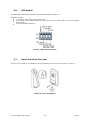
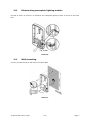
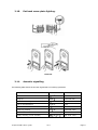
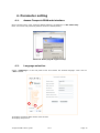
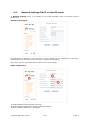
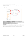
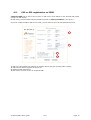
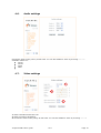
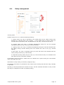
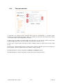
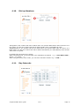
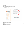
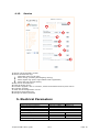
Temporis IP80 User’s guide Table of Contents 1. Basic Description……………………………. 3 2. Installation……………………………………. 4 3. Visitor at the door 2.1. Packing list ………………………………………………………………4 2.2. Modules ………………………………………………………………4 2.3. PoE or Power Supply …………………………………………………..5 2.4. Relay Connection ……………………………………………………5 2.5. Acoustic settings ……………………………………………………5 2.6. DIP Switch ………………………………………………………………6 2.7. Open and close the cover …………………………………………6 2.8. Dismounting nameplate lighting module ……………………7 2.9. Wall mounting …………………………………………………..7 2.10. Put back name plate lighting. ……………………………..8 2.11. Acoustic signalling …………………………………………………..8 3.1. Incoming calls 3.2. Outgoing calls ……………………………9 ……………………………………………………9 ……………………………………………………9 4. Parameter setting ………………………….10 5. Electrical Parameters …………………………19 6. WARRANTY 4.1. Access Temporis IP80 web interface ………………….10 4.2. Language selection …………………………………………………10 4.3. Network settings: DHCP or fixed IP mode ………………….11 4.4. Basic parameters …………………………………………………12 4.5. P2P or SIP registration on IPBX …………………………….13 4.6. Audio settings ………………………………………………….14 4.7. Video settings ………………………………………………….14 4.8. Relay management …………………………………………………15 4.9. Time parameters …………………………………………………16 4.10. Dial-up Numbers …………………………………………………17 4.11. Day Intervals …………………………………………………………..17 4.12. User interface …………………………………………………18 4.13. Service ……………………………………………………………19 …………………………………20 1. Basic Description Temporis IP80 is a SIP based IP video door phone solution. Its robustness, flexibility and wide interoperability make it ideal for any business environment. We can highlight the following features : Voice & image based on full SIP protocol Autofocus IP Camera White LED for automatic lighting of camera WEB management Firmware upgradeable from the web interface Video streaming : http jpg / http mjpg , H.263 and H.264 PoE or external power supply Ethernet – 10/100Mb SIP connection: P2P or IPBX network system Two 25-digit dial-up numbers (or IP address) Day/night switching mode Call duration extension by pressing * or # 2 relays to connect two independent locks or to control, with the second relay, another device such as camera, lighting, delayed opening etc … Two codes controlling communication hang up Two codes to trigger the 2 relays Integrated heating of printed circuit Permanent green backlight of the button Operating system – Linux 2.6 Fully integrated with Temporis IP family Supplied with Atlinks Temporis Pop-up videosoftphone Please read through this guide for a better knowledge on available functionalities and configuration capabilities you can have access to with Temporis IP80. Temporis IP80 User’s guide V1.0 Page 3 2. Installation 2.1. Packing list The following components are included in your package: Temporis IP80 Kit for wall mount Key to open the unit Name label Mini CD including user guide, Temporis Pop-up softphone, datasheets 2.2. Modules Temporis IP80 is composed of an IP module, assembled with the mother board, the PoE module and the IP camera module (picture 1) Picture 1. Basic module – mother board Temporis IP80 User’s guide V1.0 Page 4 2.3. PoE or Power Supply Temporis IP80 works either with the PoE power from the switch or with an external AC or DC power supply. The voltage must rate between 10 to 14V, the electric current doesn’t exceed 300mA. 2.4. Relay Connection Relay connection is shown on picture 2. Where NO indicates the contact which is normally open (in idle) COM indicates the common contact (middle) NC indicates the contact which is normally closed (in idle) The contacts in both switches are galvanically insulated from each other and from the circuits. Picture 2. Examples of relays connections 2.5. Acoustic settings Trimmers positions are settled in factory and in most cases will not need to be changed. Basic position, direction of rotation and meaning of the trimmers are illustrated on picture 3. Picture 3. Trimmer Setting Temporis IP80 User’s guide V1.0 Page 5 2.6. DIP Switch For DIP switch setting basic operation and default setting see picture 4. DIP switch enables to configure P2P mode or SIP server mode, to get back to the default settings (this switch must be placed back to normal position after reboot) to set the default IP adress. Picture 4. DIP switch settings 2.7. Open and close the cover Use the tool included in the package to screw/unscrew the front cover as shown on picture 5. Picture 5. Cover installation Temporis IP80 User’s guide V1.0 Page 6 2.8. Dismounting nameplate lighting module Proceed as shown on picture 6 to dismount the nameplate lighting module to access to the back hole. Picture 6 2.9. Wall mounting Use the provided dowels to wall mount Temporis IP80. Picture 7 Temporis IP80 User’s guide V1.0 Page 7 2.10. Put back name plate lighting. Picture 8 2.11. Acoustic signalling The following table shows the acoustic signals that occur during operations. Condition Tones Tone frequencies Off-hook –▄–■–▀– 425-850-1275 Hang-up –▀–■–▄ 1275-850-425 Report after calling –▄–■–▀– 425-850-1275 End of call notification –■–■–■– 1275 Parameter confirmation ––█–– Power up (reboot) –■–▄–■– 1275-850-1275 Error –■–■–■–■–■–■– 425…. Empty memory (no set number) –█–▄–■–▄–■–▄– 850-1275-1700… Temporis IP80 User’s guide V1.0 Page 8 3. Visitor at the door 3.1. Incoming calls Incoming calls from IPBX or SIP phone towards Temporis IP80 are authorized. When there is an incoming call, Temporis IP80 will ring (1 to 5 times) depending on what has been programmed in « Time parameters » section (§4.9). Call is answered automatically. Thus the caller is able to talk and trigger the relays. 3.2. Outgoing calls As soon as user presses the button Temporis IP80 initiates a call to a pre-set dial up number. Temporis IP80 button is associated to 2 different dial-up numbers (see §4.10), and can be configured to work in two different modes: Main/Backup mode: if the main destination number is busy or the call is rejected, Temporis IP80 will call the backup number saved in §4.10. Day/night mode: Temporis IP80 will dial the number programmed in §4.10 which corresponds to the current active mode-either day or night. Once the call is launched called party device will ring. Called party can answer the call, have a conversation and trigger the relays. Call duration is limited by Temporis IP80 to 2 minutes by default. 10 seconds before the end, Temporis IP80 generates a beep. The conversation can be extended by dialling * or # from the SIP device. Temporis IP80 User’s guide V1.0 Page 9 4. Parameter setting 4.1. Access Temporis IP80 web interface Open a web browser, enter Temporis IP80 IP address, (by default it is 192.168.1.250). Enter user name and password (default values are admin/admin). Picture 9. Home page & Login to setup 4.2. Language selection Select « Language » in the left panel menu and choose the desired language. Then click on « Set » button. 1 2 1: Displays Temporis IP80 camera video stream 2: Displays help screen Temporis IP80 User’s guide V1.0 Page 10 4.3. Network settings: DHCP or fixed IP mode In Network settings menu, it is possible to use DHCP automatic setup or manually enter IP parameters. Manual configuration : By default the IP address is 192.168.1.250. You may change all the parameters in this page ; default setting can be recovered by clicking on “default values” button. Once done, click on “save and restart” button to save your settings. DHCP configuration : 1 3 2 1: Enable/disable network settings via DHCP 2: DHCP assigned IP address and other settings are shown 3: Show Temporis IP80 mode – Day/Night Temporis IP80 User’s guide V1.0 Page 11 Important: if you choose DHCP setup, an IP address will automatically be assigned to Temporis IP80. Thus only a network administrator can tell you the actual IP address. You need this IP address to access the web interface or video streaming. Since IP address assignment may change in DHCP mode (e.g. after a power failure), use of fixed IP address is recommended. 4.4. Basic parameters 1 2 3 4 5 6 1: Select between Day-Night mode and Main-Backup modes for the dial-up numbers. 2: Extend call duration by pressing * or # (10 sec before call end Temporis IP80 will send a signal, the called party can extend the call by pressing * or #) 3: Enter the desired codes to hang-up the call. By default they are the same as the relay trigger codes but they can be different. 4: Enter the desired codes to switch between Day and Night modes. Note: Switching between Day and Night mode remains remains in IP80 memory even after power supply failure. 5: Select manual or automatic Day-Night mode switching. When Automatic is selected a new item will appear in the Menu called “Day Intervals” (see §4.11). Please note NTP server must be enabled for this feature to work. 6: In Auto mode backlight leds will be turned on if dim or dark background is detected. Temporis IP80 User’s guide V1.0 Page 12 4.5. P2P or SIP registration on IPBX Temporis IP80 can be set to peer-to-peer or SIP server mode thanks to the internal DIP switch (see § 2.5. DIP Switch). In P2P mode, Temporis IP80 calls an IP address saved in «Dial-up numbers» (see §4.10). If you set Temporis IP80 to SIP server mode, you will have to fill in the SIP parameters menu. 1 2 3 4 1: 2: 3: 4: SIP proxy and registrar IP address or domain names and port (usually 5060 or 5061) SIP account data to register on the server Additional SIP parameters Not used in current version of Temporis IP80 Temporis IP80 User’s guide V1.0 Page 13 4.6. Audio settings Choose the audio codec priority for SIP calls. You can also disable a codec by choosing “-------“ Available codecs are: G711µ G711a G726 GSM 4.7. Video settings 1 2 3 1: Video resolution and frame rate 2: Video correction parameters 3: Choose the video codec priority for SIP calls. You can also disable a codec by choosing “-------“ Temporis IP80 User’s guide V1.0 Page 14 4.8. Relay management 1 2 3 4 5 1: Relay mode: Possible values are 1 to 5, with the following meaning : 1: trigger mode: the relay is activated by the called party for the “Relay closing” time duration (eg: electrical locks, door opening …). If the called party is using a phone, he must dial the corresponding code. By default 55 for the relay 1 and 66 for the relay 2. 2: Camera mode: The relay is activated automatically during the call and released immediately when the call is over (eg: external camera) 3: Lighting mode: The relay is activated automatically during the call and released after the “Relay closing” timeout starting from the moment the call is over (eg: external lighting) 4: Bell mode: The relay is activated when you press the button and released after the “Relay closing” timeout (eg: external bell). 5: Sequential opening mode (only for relay 2): in this mode the relay 2 is activated some time after the relay 1 has been released. 2: Activation code from phone: DTMF code to be dialed from a phone during the conversation which will trigger the relay. 3: Duration of relay closing in seconds (2 digits [01-99] ) 4: Incoming call Control: to prohibit the relay control by an incoming call when the relay is already in operation. 5: Delay (in seconds) between the release of relay 1 and the automatic activation of relay 2 when the relay 2 is configured in mode 5 (2 digits [01-99] ). Temporis IP80 User’s guide V1.0 Page 15 4.9. Time parameters 1 2 3 4 5 6 1: Maximum call duration before Temporis IP80 hangs up automatically. 10 seconds before hanging-up, Temporis IP80 generates a beep. It’s possible to extend the call duration by pressing * or # (depending on the configuration, see §4.4). 2: When calls from IPBX to Temporis IP80 are authorised, you can set the number rings before Temporis IP80 picks-up the call. The number of rings can be set from 1 to 9. 3: Time (sec) Temporis IP80 will hang-up before redialling when the called party is busy (range [1-5]). 4: Time (sec) Temporis IP80 will stay in calling mode (hear the ring back tone) before hanging-on then redialing, when the called party doesn’t answer (range [10-99]). 5: Enable/disable the acoustic signalling of pick-up and hang-on actions. 6: Enable/disable the acoustic signalling of other actions, like relay activation,… Temporis IP80 User’s guide V1.0 Page 16 4.10. Dial-up Numbers 2 1 1:Day/Main is the number that will be dialed when user presses IP80 button while the device is in Day mode. It is also the number that will be dialed initially when in Main/Backup mode. 2:Night/Backup is the number that will be dialed when user presses IP80 while the device is in Night mode. It is also the number that will be dialed automatically if in Main/Backup mode and the call to Main is rejected By default Dial-up Numbers are empty. When using P2P mode, you should enter your destination IP address e.g . « 192*168*1*250 », where « * » means « . » , When using SIP proxy server mode, you can save extension numbers e.g. « 1234 ». 4.11. Day Intervals Temporis IP80 User’s guide V1.0 Page 17 When Automatic switching between day and night mode is selected (see §4.4) this menu becomes available in the menu list. Fill in the day intervals for each day of the week. The remaining intervals will be the considered as night mode. Note: Time server must be up and running (see §4.12) 4.12. User interface 1 2 3 4 5 1: Displays the video on login page 2: Requires the password to display the video stream. Only a web browser will be able to display video 3: Enables video surveillance using codec H.264 4: Modifies the web interface port 5: Enables telnet service Temporis IP80 User’s guide V1.0 Page 18 4.13. Service 1 2 3 4 5 6 7 8 9 1: Shows current firmware version 2: Shows the different logs: Download event log (All logs) Show call log (incoming and outgoing call log) Show register log (all the logs related to SIP registration) Show VoIP log (All VoIP traces) 3: NTP server and time zone 4: External Syslog server 5: Firmware upgrade: click on “browse”, select the firmware file then press “save”. 6: Language upgrade 7: Save current configuration in a file. 8: Upload a configuration file 9: Change the admin password 5. Electrical Parameters Parameter Communication interface VoIP protocol supported Bandwidth Power supply Max. consumption Max. voltage of switch contact Max. current of switch contact Operational temperature Temporis IP80 User’s guide Value Conditions Ethernet 10Base-T, 100Base-TX SIP 300Hz – 3400Hz 12V ± 2V AC or DC 300mA 12Vss 48V at I < 1A 2A at U < 30 V - 20 to + 50°C V1.0 Page 19 6. WARRANTY Please read carefully the user’s guide included in this package. This product is certified as conforming to European technical standards, as evidenced by the CE Mark affixed thereto. The product you have just bought is a technological product, which must be handled with care. UK legislation, including Sale of Goods Acts and regulations, imply certain conditions which may apply to the product you have purchased from the retailer (statutory warranty). These include conditions relating to quality. For information concerning the statutory warranty, please consult the retailer who sold the product to you (seller). Without prejudice to any statutory warranty from which the product benefits, ATLINKS Europe whose registered office address is at 22 quai Gallieni 92150 Suresnes France warrants that the product contained in this package complies with the technical specifications set forth in the user’s guide, during a warranty period commencing on the date of purchase of an unused Product, which shall be presumed to be the date appearing on the invoice or the receipt issued by the seller, upon which appears the seller’s name and continuing for: Twenty-four (24) months for the telephone, excluding consumables, accessories and batteries. Together with any claim made under this warranty during the warranty period, the complete Product must be returned to the seller as soon as the defect appears or is discovered, together with proof of purchase, consisting of an invoice or receipt issued by the seller specifying the place of purchase and the serial number of the Product. Any Product or Product part found, during the warranty period, to have a defect in design, materials or workmanship shall be repaired or replaced, at no cost to you, by a product or part that is identical or at least equivalent in terms of function and performance. If repair or replacement is not possible on a commercially reasonable basis, ATLINKS will refund the purchase price of the Product or replace the Product by an equivalent product. The repaired or replaced Product or part, which, may be new or refurbished, shall be under warranty for a period of ninety (90) days from the date of repair or replacement, or until the end of the initial warranty period if that exceeds the said ninety (90) days; the warranty period shall also be extended by any period exceeding six days between the date the defective Product is delivered to the seller and the date that the repaired or replaced Product is placed at your disposition. This warranty does not apply in case of: damage caused by installing or using the Product otherwise than in accordance with the instructions contained in the user’s guide; improper connection or abnormal use of the Product, in particular together with incompatible accessories, as stipulated in the user’s guide; a Product that has been opened, modified or fitted with unapproved replacement parts; removal of the serial number or defacement rendering the serial number illegible; normal wear and tear, including normal wear and tear of accessories, batteries and screens; non-compliance with technical and safety standards in force in the geographical area of utilization; Products having suffered an impact or a fall; damage caused by lightning, power surge, proximity to a source of heat or radiation, water damage, exposure to excessive temperature, humidity or other environmental conditions or any other cause external to the Product; Temporis IP80 User’s guide V1.0 Page 20 negligent or defective maintenance; damage caused by servicing, modification or repair performed by any person other than an authorized ATLINKS service provider. If the returned Product is not covered by the warranty, you will receive a repair estimate giving the processing cost and the transport fees that will be charged if you wish the Product to be returned to you. This warranty is applicable where the Product is lawfully purchased, in the United Kingdom. All warranties other than the warranty set forth herein are expressly excluded. Nothing in this warranty shall exclude or limit conditions or warranties implied by law including the statutory warranty. ATLINKS shall: (a) only be responsible to you for losses suffered by you that are a foreseeable consequence of a defect in the Product; (b) not be responsible to you for losses that result from a defect in the Product which fall into the following categories: (i) loss of income or revenue; (ii) loss of profit; (iii) loss of business; (iv) loss of anticipated savings; (v) loss of data; (vi) any waste of time; or (vii) downtime or loss of use; However this clause shall not prevent claims for foreseeable loss of, or damage to, your physical property; Nothing in this warranty excludes or limits in any way ATLINKS liability for: (i) death or personal injury caused by our negligence; (ii) fraud or fraudulent misrepresentation; (iii) any breach of the obligations implied by section 12 of the Sale of Goods Act 1979 or section 2 of the Supply of Goods and Services Act 1982; (iv) defective products under the Consumer Protection Act 1987; or (v) any other matter for which it would be illegal or unlawful for ATLINKS to exclude or attempt to exclude liability. Declaration of conformity for the European Community ATLINKS declares that the Temporis IP80 complies with the relevant basic requirements and provisions of the European directive 1999/5/CE. You can download the declaration of conformity from the following address: www.atlinks.com. The CE logo shown on the products indicates that they are compliant with the basic requirements of all the applicable directives. Temporis IP80 User’s guide V1.0 Page 21 Environment This symbol means that your inoperative electronic appliance must be collected separately and not mixed with the household waste.The European Union has implemented a specific collection and recycling system for which poducers' are responsible. This appliance has been designed and manufactured with high quality materials and components that can be recycled and reused. Electrical and electronic appliances are liable to contain parts that are necessary in order for the system to work properly but which can become a health and environmental hazard if they are not handled or disposed of in the proper way. Consequently, please do not throw out your inoperative appliance with the household waste. If you are the owner of the appliance, you must deposit it at the appropriate local collection point or leave it with the vendor when buying a new appliance. (a)- If you are a professional user, please follow your supplier's instructions. (b)- If the appliance is rented to you or left in your care, please contact your service provider. Please help us protect the environment in which we live! ATLINKS Europe 22, Quai Gallieni - 92150 Suresnes - France S.A.S. (Simplified Joined Stock Company) with capital of 500 000 euros - Registration number: 508 823 747 R.C.S. Nanterre ATLINKS 2011 - Reproduction prohibited. The manufacturer reserves the right to modify the specifications of its products in order to make technical improvements or comply with new regulations. ALCATEL, TEMPORIS and ATLINKS are registered trademarks.The Alcatel logo and Alcatel name are trademarks of Alcatel and used under license by ATLINKS. Temporis IP80 User’s guide V1.0 Page 22