1
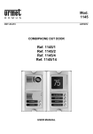
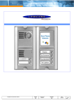
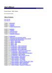
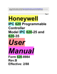
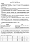
Link SIP Door Phone
Manual
V1.0
Linkcom France
11 rue du Soleil Levant 92140 CLAMART
1
Copyright © 2008 – Linkcom – Tous droit réservés
Table of Contents
1. BASIC DESCRIPTION ......................................................................3
1.1. FEATURES .................................................................................... 3
1.2. MODULE ASSEMBLY ......................................................................... 3
2. MODULE FEATURES ........................................................................4
2.1. BASIC MODULE .............................................................................. 4
2.2. RELAYS CONNECTION ........................................................................ 4
2.3. ACOUSTIC SETTING .......................................................................... 5
2.4. EXTENDING MODULE: UCM (MASTER), UCE (SLAVE) ................................. 5
2.5. KEYBOARD MODULE - UCK................................................................. 6
3. INSTALLATION ...............................................................................7
3.1. INSTALLATION ON PLASTER ................................................................. 7
3.2. FLUSH-MOUNTED INSTALLATION ........................................................... 7
3.3. CHANGE OF NAMEPLATES .................................................................... 7
3.4. ACOUSTIC SIGNALING....................................................................... 9
4. VISITOR AT DOOR ..........................................................................9
4.1. SIP DOOR PHONE WITHOUT KEYBOARD................................................... 9
4.2. SIP DOOR PHONE WITH KEYBOARD ....................................................... 9
4.3. INCOMING AND OUTGOING CALLS ....................................................... 10
5. PROGRAMMING OF PARAMETERS .................................................10
5.1. CHOOSING A MODE AND LOGIN ........................................................... 10
5.2. LANGUAGE OPTION ........................................................................ 11
5.3. NETWORK SETTINGS: DHCP OR FIXED IP MODE ....................................... 11
5.4. PEER TO PEER OR SIP SERVER CONNECTION ............................................ 12
5.5. SETTING AUDIO ........................................................................... 13
5.6. SETTING VIDEO ............................................................................ 14
5.7. SERVICE .................................................................................... 14
6. SETTING DOOR PHONE PARAMETERS ...........................................15
6.1. BASIC PARAMETERS ....................................................................... 15
6.2. RELAY MANAGEMENT....................................................................... 16
6.3. TIME PARAMETERS ......................................................................... 17
6.4. DIRECT DIALING – MEMORIES ........................................................... 18
7. TECHNICAL PARAMETERS.............................................................19
7.1. ELECTRICAL PARAMETERS ................................................................. 19
7.2. MECHANICAL DIMENSIONS ................................................................ 19
Linkcom France
11 rue du Soleil Levant 92140 CLAMART
2
Copyright © 2008 – Linkcom – Tous droit réservés
1. Basic Description
1.1. Features
Modular system allows to connect 4 to 64 buttons
Possibility to connect a numerical keyboard this way that the guard can include 4 - 18 standard buttons
Voice & Image based on Full SIP protocol
Two key with 16digit numbers or IP address saving
Day/night switching feature
Extending call duration by pressing * or #
2 Relays with Possibility to connect two independent locks
Possibility to control with the second Relay (e.g. camera, lighting, delayed opening)
Two codes prefix controlling communication hang off
Two codes prefix for door opening
Six locks password - 3 per relay ( Night, Day, Day/Night)
Integrated heating of printed circuit
Permanent lighting through visiting cards
Included color IP camera
Ethernet – 10/100Mb with standard 10BaseT a 100BaseTx
Web server for remote configuration
Operating system – Linux 2.6
SIP connection P2P or PBX network system
WEB – firmware upgradeable
1.2. Module Assembly
The SIP Door Phone structural elements are the basic modules with color camera and extending button modules
with one button, two buttons, and four buttons. Further it is possible to provide the assembly with numerical
keyboard. The complete assembly consists similarly to Door Phone system of max. 4 modules in column and max. 3
columns side by side.
UC-IP
UC-IP-CAM
FMB
IP1
SMB
IP2
UCA
IP4
UCM
LM
UCE
UCK
BM
Examples of frame configuration:
Linkcom France
11 rue du Soleil Levant 92140 CLAMART
3
Copyright © 2008 – Linkcom – Tous droit réservés
2. Module Features
2.1. Basic Module
Link SIP Door phone is based on IP module, assembled with the mother boards and IP Camera circuit (picture 1)
Picture 1
Basic module - motherboard
The « 14 pin black conector » serves the connection of extending modules by means of flat cable. It will be
necessary to power the door phone with AC voltage of 10-15Vst or DC voltage of 12-18Vss must be energized to
“12V” terminal, Not exceed 300mA.
Power is needed for system lighting, System Heating, lock(s), and then it is necessary to consider the electrical lock
demand. In practice the alternating feeder 12V/1A mostly meets these demands.
2.2. Relays connection
Relay connection is shown on Picture. 2. Where
•
NO means idle-disconnected contact,
•
COM means a pin contact (middle)
•
NC means an idle-connected contact.
The contacts of both switches are galvanically isolated from each other and from the circuits.
Picture 2 Examples of relays connections
Linkcom France
11 rue du Soleil Levant 92140 CLAMART
4
Copyright © 2008 – Linkcom – Tous droit réservés
2.3. Acoustic setting
Trimmers position are presetted in factory and in major cases will not need to be changed. Basic position of the
trimmers, sense of rotation and meaning are illustrated on picture 3.
Picture 3 Setting of trimmers
Picture 4
DIP switch settings
DIP switch setting basic operation and default setting. See on picture 4.
2.4. Extending Module: UCM (Master), UCE (Slave)
The UCM (Master) module (picture 6) has four buttons and includes the electronics to be connected to IP1/2/4
module or previous UCM module. This module is only connected by flat cable, buttons and lighting through is already
interconnected.
The UCE (salve) module is always connected to UCM module or IP1/2/4 module. The connection is not prepared
and should be done by conductors. see on picture 5.
Picture 5 – module connection
Linkcom France
11 rue du Soleil Levant 92140 CLAMART
5
Copyright © 2008 – Linkcom – Tous droit réservés
The flat cable connection is facilitated by connector locks, preventing from rotation, but to keep the connection
routing is imperative.
Picture 5 - IP4 module
2.5. Keyboard Module - UCK
The keyboard module is only connected by flat cable as well as UCM module. The only difference is that keyboard
module is always the last in row. Connect on the first place (to output of the l’IP1/2/4) or the second (to output of
the first UCM) positions. It means that 4 to 16 buttons with direct dialing can be used instead of keyboard (per
assembly). The most frequent used assemblies are:
Attention when you programming, the position of keyboard connected must be correctly specified.
The choice is entered by gradual pressing of buttons with digits. Firstly the key symbol must be pressed to enter a
password. When pressing X, the DoorPhone will hang up.
Linkcom France
11 rue du Soleil Levant 92140 CLAMART
6
Copyright © 2008 – Linkcom – Tous droit réservés
3. Installation
3.1. Installation on Plaster
By installation on plaster only the surface mount box , with a rain protective cover SMB is used, which will include all
mechanical parts. The installation is made by screwing to the wall by means of dowels. See SMB1 on figure.
3.2. Flush-Mounted Installation
The FMB mounting box is built-in wall. Be careful in orientation of assembling holes when nearly MK1 square box is
used, it must be in vertical axis. The well-embedded box is shown on figure.
The Protecting Frame (provides overlapping of unevenness after mounting box walling-in) and Canopy (necessary for
installation in external areas) form other accessories for flush-mounted installation. When installed in surroundings
with possible water condensation (temperature changes) or water spraying (rain) it is recommended to connect the
jumper on Main module - heating ON.
The board heating has two positive functions partly it heats up the electronics in winter at temperatures below -20C
(most details with extended temperature range has guaranteed parameters from -20C) and partly with external
installation at swift temperature changes and higher air humidity by relayed heating no water condensation occurs on
Main Doorphone board, which assures its reliable function.
3.3. Change of nameplates
The first step is dismantling of a fixing frame from module, where we want to change a nameplate. It can be
executed by unscrewing of two screws under plastic covers on fixing frame. When removing the fixing frame we can
see two independent modules.
The front part (metallic) of the button module has to be first separated from plastic part in this way that we will put
off the plastic lug, ensuring the front part on the right side. Each button has its separate nameplate hold by means of
plastic flag (see figure). The paper nameplates can be printed from Excel form.
Linkcom France
11 rue du Soleil Levant 92140 CLAMART
7
Copyright © 2008 – Linkcom – Tous droit réservés
Picture 6 Mechanical assembly parts
Linkcom France
11 rue du Soleil Levant 92140 CLAMART
8
Copyright © 2008 – Linkcom – Tous droit réservés
3.4. Acoustic Signaling
The following board shows the acoustic signals that occur during operation. A Lighting signal is also available through
the red LED (placed under microphone hole).
Condition
Tones
Tone frequency
LED
––––
425-850-1275
glows
–––
1275-850-425
goes out
Report after calling
––––
425-850-1275
glows
Notice about call end
––––
1275
glows
Line lifting up
Line hanging up
Parameter confirmation
––––
Switch on (Reset)
glows
––––
1275-850-1275
Error (anything, if unsuitable)
–––––––
425….
Empty memory (no progr. numb.)
–––––––
850-1275-1700…
blinks
4. Visitor at Door
The function is influenced partly by used module assembly, with keyboard or without it, and partly by setting
parameters.
4.1. SIP Door Phone without Keyboard
To each button is associated Name of Company or physical Person name. To each button is associated 2 Call
numbers (Table 1 and Table 2)
The visitor will press the corresponding button, the SIP Door Phone manage to make the call through the VoIP
channel. If the SIP Door Phone is programmed with the following
•
•
•
•
Group Mode:
if after a number of Ring called party do not answer the SIP Door Phone will manage to call se second
number saved in table 2.
Day/night mode: In Day mode, the SIP Door Phone will always dial the number programmed in table
1. In Night mode, the SIP Door Phone will always dial the number programmed in table 2.
code lock Allow opening the gate by dialing a specific Password. It can be controlled by the 2 buttons of
SIP Door Phone. If visitor presses buttons in such combination that meet the preprogrammed day,
Night or Day/Night password code within the laps of time duration between each presses buttons set on
time table, then the SIP Door Phone will trigger the corresponding relay.
4.2. SIP Door Phone with Keyboard
The SIP Door phone with keypad can also include besides the keypad up to 10 buttons of direct dialing except the
code lock. After keypad is connected, the position of the keypad is connected should be set. The keypad has two
functional buttons :
• key symbol, once pressing the numerical combination is considered as the combination for control the
relays.
•
X symbol, when pressing the SIP Door Phone immediately will hang up.
The number selection on keypad can be executed in two ways :
• The incoming person is dialing number as to be done on phone. The period among button presses should be
lower than the value given by setting. After this period the SIP Door Phone will lift up and dial the given
number.
• On buttons the incoming person is dialing a two-digit number (from 01 to 64), which represents the memory
number, where the 16-digit number is stored (same as for buttons). The number dialing is managed by
Day/Night setting or mode for two groups of numbers.
Linkcom France
11 rue du Soleil Levant 92140 CLAMART
9
Copyright © 2008 – Linkcom – Tous droit réservés
4.3. Incoming and Outgoing Calls
Incoming Call :
Incoming calls from IPBX or SIP phone are authorized, When a call is performed the SIP Door Phone will ring from
[1 to 5 ] rings depend what is programmed in table call is picked up automatically and caller is able to speak with the
SIP Door Phone and trigger the Relay1 or 2 .
Outgoing Call :
Outgoing calls from SIP Door Phone to IPBX or SIP phones are available by pressing one of the 2 buttons.
IPBX and or SIP phone will ring:
If called party pick up the call conversation take place and called party can trigger Relay 1 or 2
If called party do not pick up the call after a preprogrammed N° of Ring
o Either the SIP Door Phone is programmed in DAY/NIGHT mode in this case call ends
o Either SIP Door Phone is programmed in mode Group in this case a second call is performed to the
number programmed in Table 2 ( See Page 16 )
In both cases, Incoming or outgoing call, Conversation can be extended by dialing from the SIP phone (* or #) after
hearing the tone 10 seconds before call end.
5. Programming of Parameters
5.1. Choosing a mode and login
It is important to choose the SIP Door Phone mode first. The SIP Door Phone work in PeerToPeer or SIP server
mode. The mode setting depend on the Dip Switch position (picture 8). In SIP server mode it is possible to choose
SIP server (external). It can be set in a configuration interface of the SIP Door Phone.
Picture 7
Linkcom France
11 rue du Soleil Levant 92140 CLAMART
DIP switch setting
10
Copyright © 2008 – Linkcom – Tous droit réservés
In your web browser enter IP address of the SIP Door Phone, default is « 192.168.1.250 ». See Picture 8. Enter
user name and password. default User name is « admin », password is « 1234 ». See picture 10.
Picture 8 First site
video from camera
Picture 9 Login to setup
5.2. Language option
Select « Language » in the left panel menu choose the language then clic « Set »Button.
5.3. Network settings: DHCP or fixed IP mode
In « Network setting » menu, It is possible to use DHCP automatic setup or enter manually IP addresses.
After making all changes click on a « save and restart » button. Restarting is mandatory for those steps
Linkcom France
11 rue du Soleil Levant 92140 CLAMART
11
Copyright © 2008 – Linkcom – Tous droit réservés
Manual configuration :
1
2
1 : Enable/disable ethernet settings via DHCP
2 : Default value – presetings to the firm settings. After making changes click on a « save and restart » button
DHCP configuration :
1
3
2
4
1
2
3
4
:
:
:
:
Enable/disable ethernet settings via DHCP
Show automatic DHCP generate IP adress and othet settings
Show mode of DoorPhone – Day/Night
Return to the video from color camera screen
Important: if you choose DHCP setup, it will automatically assigne an IP address to SIP Door Phone and network
administrator must tell you actual address, to display video in web browser. Because assigning IP adress can change
after e.g . power failure, We recommend the setting of SIP Door Phone fixed IP address.
5.4. Peer to peer or SIP server connection
The SIP Door Phone can be set to the peer to peer (P2P) mode or to the SIP server mode by DIP switch (page 8).
In P2P mode SIP Door Phone calling IP adress in « memory numbers » (page 15).
If you setting SIP server mode by DIP switch, so add in menu item SIP parameters
Linkcom France
11 rue du Soleil Levant 92140 CLAMART
12
Copyright © 2008 – Linkcom – Tous droit réservés
1
2
1 : SIP proxy server IP adress or the SIP server name and port (usually 5060 or 5061)
2 : Registering data to SIP proxy server
5.5. Setting Audio
Choose the
•
•
•
•
audio codec priority for SIP calls. There codec are available:
G711u
G711a
G726
GSM
Linkcom France
11 rue du Soleil Levant 92140 CLAMART
13
Copyright © 2008 – Linkcom – Tous droit réservés
5.6. Setting video
1
2
3
1 : Resolution display video
2 : Number of picture per second (frequency restoring picture)
3 : Setting next parameters of camera
5.7. Service
1
2
3
4
5
6
1
2
3
4
5
6
:
:
:
:
:
:
Show firmware version
Event log (enhanced or basic log)
Download event log
Firmware upgrade
Language upgrade
Admin password change
Linkcom France
11 rue du Soleil Levant 92140 CLAMART
14
Copyright © 2008 – Linkcom – Tous droit réservés
6. Setting Door Phone Parameters
6.1. Basic Parameters
1
2
3
5
4
6
1 : Select between Day/Night mode or 2 Group of Number
2 : Extending call duration by pressing select * or # (10 sec before call end the Slim IP Door Phone will send a
signal, the called party can extend the call by pressing * or #)
3 : Two commands in order to hang up the SIP Door Phone using 2 digits.The advantage is to set the same
command both for switch closing and command to guard hanging up.
4 : Relay trigger prefix DAY / NIGHT mode switching. Note: The relay trigger prefix remains even after power
failure.
5 : With « Direct choice number », it dialing as on normal telephone (all number of called person should be
pressed on keyboard). This mode is recommended for use SIP proxy server mode.
With « Choice of numbers from Memory », only 2-digit memory number is entered on keyboard by which the
number of called person is stored (memory number corresponds to button number with respect to Day/Night
switchover). This mode is recommended for use P2P.
6 : Keyboard position :
0 : only UCK connected to the basic module
1 : the keyboard connected on the first position (after IP1/2/4)
2 : the keyboard connected on the second position (after first UCM)
3 : the keyboard connected on the third position (after second UCM) explanation of position Keyboard.
Linkcom France
11 rue du Soleil Levant 92140 CLAMART
15
Copyright © 2008 – Linkcom – Tous droit réservés
6.2. Relay management
1
2
3
4
5
6
1 : Relay mode:
1 = Trigger mode – Used to trigger the relay when called party dial the Internal Code phone (used for
electrical locks, gate opening etc.)
2 = camera mode – Trigger on an outside camera
3 = lighting mode – Trigger lighting system based on temporized timeout.
4 = bell mode – Trigger on a external Bell.
5 = Temporized opening modes – this mode is available only for relay 2
It has to work together with relay 1, set in mode 1. When relay 1 is activated then relay 2 will trigger after time
period set in t3. Then the relay 2 is activated for t2 period.
Note: when Relay 1 is activated relay 2 will automatically activated after a Temporized period. Besides that the
relay 2 can be separately activated from buttons by Day and Night password.
2 : Day/Night password allows you by a combination on the 2 available buttons [2 to 6 digits] to trigger one of the
2 Relay and open the gate. Total 3 passwords by relay are available Day/Night Mode then Day then Night mode.
If 2 number groups are selected I the programming tables the Slim IP Door Phone is permanently in DAY mode.
Some rules have to be observed when choosing a password: Make sure that Password for relay 1 do not include
the same streaming numbers for Relay 2 e.g. relay 1 has 1221 and relay 2 has 12212, mean after reaching
combination 4 Relay one will be activated.
3 : Duration of relay closing in second [2 digits 01-99]
4 : To prohibit the control during incoming call it is important e.g. when using relay 2 in mode 1 for control of garage
gate opening, when the electronics opens the gate and the gate is closed by car passage. Then the control from
phone could undesirably cause the permanent gate opening (not closed – no car passage).
6 : Time in second between close relays 1 and 2 by mode setting of relay 2 is 5 (gradual opening) [2 digits 01-99]
Linkcom France
11 rue du Soleil Levant 92140 CLAMART
16
Copyright © 2008 – Linkcom – Tous droit réservés
6.3. Time Parameters
1
2
3
4
5
6
7
1 : max. call duration before SIP Door Phone hangi up, this time can be extended during a call by dialing * or # .
2 : Calls from IPBX to the SIP Door Phone are authorised, you can set the number of Slim IP Door Phone
rings befor picking up the call – LED on front panel blinking. The number of ring can be set from 1 to 9.
3 : max. time [range 1-9 sec] authorized for password in between button presses
if time between two presses key is bigger than time set, Password code is not evaluated correctly.
if the button pressed, is the first password number the dialing is postponed by this time.
4 : time [sec] for which the SIP Door Phone will hang up, before repeated dialing (button pressing during call or
dialing, busy tone detection) [range 1-5]
5 : Ring Tone Time out after SIP Door Phone Button 1 or 2 are pressed and the system dial the extension N° if no
answered from the IPBX side after this laps of time the SIP Door Phone will hang up [range 10-99] and then will
redial the second Group N° in case 2 groups mode is set.
6 : By default acoustics signaling pick up / hang up box is ticked, If signalling perturb your IPBX you can cancel it.
7 : By default acoustics signaling Others tones box is ticked. Signaling is available when pressing key 1 or 2, when
door phone is calling and when doorphone hangs up. If signalling perturb your IPBX you can cancel it.
Linkcom France
11 rue du Soleil Levant 92140 CLAMART
17
Copyright © 2008 – Linkcom – Tous droit réservés
6.4. Direct Dialing – Memories
1
2
1 : telephone number up to 16 digits, we want to store. The numbers are the numbers of the first group or
numbers of Day mode. In default setting is table memoirs empty. While using setting P2P to the memoirs saves
IP address e.g . « 192*168*1*250 », where « * » means « . » , while using SIP proxy server to the memoirs
saves phone number e.g. « 117 ».
2 : telephone number up to 16 digits, we want to store. The numbers are the numbers of the second group or
numbers of Night mode. In default setting is table memoirs empty. While using setting P2P to the memoirs saves
IP address e.g . « 192*168*1*250 », where « * » means « . » , while using SIP proxy server to the memoirs
saves phone number e.g . 117.
Note: The switchover to Day/Night mode remains set in DoorPhone even after power supply disconnection.
Linkcom France
11 rue du Soleil Levant 92140 CLAMART
18
Copyright © 2008 – Linkcom – Tous droit réservés
7. Technical Parameters
7.1. Electrical Parameters
Parameter
Communication interface
VoIP protocol supported
Band width
Power supply of lighting through, switches and heating
Max. consumption
Max. voltage of switch contact
Max. current of switch contact
Operational temperature
Value
Conditions
Ethernet 10BaseT, 100BaseTx
SIP
300Hz – 3400 Hz
12Vss ± 2V , 10-12Vst ± 2V
300mA
12Vss
48V
at I < 1A
2A
at U < 30 V
- 20 to + 50°C
7.2. Mechanical dimensions
Type of item
FMB mount. box
SMB 1col.
SMB (on plast.)2col.
Linkcom France
11 rue du Soleil Levant 92140 CLAMART
1 module
114x118x45
151x157x79
-
dimensions HxWxD [mm]
2 modules
3 modules
204x118x45 294x118x45
241x157x79 331x157x79
241x286x79
-
4 modules
384x118x45
421x157x79
421x286x79
19
Copyright © 2008 – Linkcom – Tous droit réservés