1
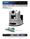
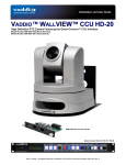
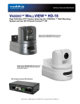
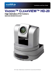
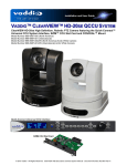
Installation and Guide Cameras and Electronic Product for Integrators Vaddio™ WallVIEW™ CCU HD-18 HD-SDI High-Definition HD-18 PTZ Camera featuring the EZIM HD-SDI Slot Card and Quick-Connect CCU Model Number 999-6908-000 (North America) Model Number 999-6908-001 (International) Model Number 999-6908-000W (North America) Model Number 999-6908-001W (International) Arctic White Version EZIM HD-SDI Card for HD-18 Quick-Connect CCU for HD-18 ©2010 Vaddio - All Rights Reserved. WallVIEW CCU HD-18 SDI - Document Number 341-988 Rev. A WallVIEW CCU HD-18 HD-SDI WallVIEW CCU HD-18 HD-SDI Overview Figure 1: Quick-Connect HD-18 CCU With the WallVIEW CCU HD-18 HD-SDI PTZ camera and CAT 5e cabling system, Vaddio delivers a solution that allows for easy installation and integration and ultimate flexibility for the most demanding of users. The camera is built around a 1.3 megapixel, 1/3” CCD with an 18x optical zoom lens, making it the ideal choice for a wide range of high definition video applications. The HD-SDI output of the included HD-SDI Slot Card can be configured as either HD ([email protected]/50Hz, [email protected]/50Hz or 1080p@60/59.94/50/30/250Hz (yep, it’s 3Gb/s capable for HD-SDI outs), or SD (480i/29.97 or 576i/25). Because the camera module is built around a CCD image sensor, the HD-18 is excellent in low-light situations, with a 1.8 LUX rating. In addition, the video signal to noise ratio output of the camera is greater than 50dB, delivering clean, crisp, and clear video. The multi-element motorized zoom lens allows WallVIEW CCU HD-18 HD-SDI to capture a wide angle of view (55.2°) enough to view everyone at a conference room table, as well as capture an individual from a long distance (3.2°). The zoom range provides greater flexibility for a wide variety of applications. The pan range of the HD-18 is ±170 and tilt range is -30 to +90 degrees. Vaddio’s Quick-Connect CCU Power and Control Interface and EZIM HD-SDI Slot Card are part of this system. The CCU provides power and control up to 500 feet over two (2) CAT 5e cables. The CCU allows users to control a variety of image controls built into the camera, including iris, red and blue gain, pedestal, knee, gamma, chroma and gain. The HD-SDI/SDI signal with 3Gb/s compatible transmitter are returned over a single coax cable. To summarize, the wiring out to this camera system is two (2) CAT 5e cables and one coax. The WallVIEW CCU HD-18 HD-SDI is an exceptional camera system for integration projects, since no power supply is required at the camera location. Use the WallVIEW CCU HD-18 HD-SDI for high definition camera applications, such as houses of worship, corporate boardrooms, live event production and distance-learning. Intended Use: Before operating the Vaddio WallVIEW CCU HD-18 HD-SDI, please read the entire manual thoroughly. The system was designed, built and tested for use indoors, and with the provided power supply and cabling. The use of a power supply other than the one provided or outdoor operation has not been tested and could damage the camera and/or create a potentially unsafe operating condition. Important Safeguards: Read and understand all instructions before using. Do not operate any device if it has been dropped or damaged. In this case, a Vaddio technician must examine the product before operating. To reduce the risk of electric shock, do not immerse in water or other liquids and avoid extremely humid conditions. Use only the power supply provided with the WallVIEW CCU HD-18 HDSDI system. Use of any unauthorized power supply will void any and all warranties. Please do not use the “pass-thru” RJ-45 type connector. Please use standard RJ-45 connectors for best results. Save These Instructions: The information contained in this manual will help you install and operate your Vaddio WallVIEW CCU HD-18 HD-SDI. If these instructions are misplaced, Vaddio keeps copies of Specifications, Installation and User Guides and most pertinent product drawings for the Vaddio product line on the Vaddio website. These documents can be downloaded from www.vaddio.com free of charge. WallVIEW CCU HD-18 HD-SDI Manual 341-988 Rev. A Page 2 of 26 WallVIEW CCU HD-18 HD-SDI UNPACKING: Carefully remove the device and all of the parts from the packaging. Unpack and identify the following parts: • One (1) ClearVIEW HD-18 PTZ Camera • One (1) Quick-Connect CCU Interface for HD-18 • One (1) IR Remote Control • One (1) EZIM HD-SDI Slot Card for HD-18 • One (1) Wall Mount and Hardware • One (1) RJ-45 to DB-9 Adapter • One (1) Vaddio PowerRite 36 VDC, 2.78 Amp Power Supply • One (1) AC Cord Set (US - North America - or - UK and Europe - International) • Documentation and Manuals THE COMPONENTS: • The Camera Figure 2: ClearVIEW HD-18 PTZ Camera (front) 1 3 2 1. 2. 3. 4. 4 Camera – A 1/3”, 1.3 megapixel HD image sensor is combined with an 18x optical zoom lens, for capturing high-quality video. Tally Light – A tally light is illuminated when the camera receives a VISCA command or from the CCU tally port on the back of the Quick-Connect CCU. IR Sensors – Dual IR sensors are built into the front of the WallVIEW CCU HD-18 HD-SDI to receive IR signals from the IR remote control supplied with the camera. Power Light – A power light is illuminated when the camera is turned on. Compatible Switchers and Joystick Controllers (not included in this package): ProductionVIEW HD-SDI (999-5650-000/001) WallVIEW CCU HD-18 HD-SDI Manual 341-988 Rev. A Precision Camera Controller (999-5700-000/001) Page 3 of 26 WallVIEW CCU HD-18 HD-SDI The Components (continued) Figure 3: WallVIEW HD-18 camera (back) 5 9 6 10 7 11 12 8 Rear of WallVIEW HD-18 5. 6. 7. 8. 9. 10. 11. 12. RS-232 In & IR Out – The RS-232 accepts modified VISCA™ protocol for camera control, as well as transmits IR signaling received by the IR receivers, which can be transmitted to third party devices. DIP Switch Settings – Settings for IR remote, baud rate, SD output format, image flip can be configured on these switches. See page 6 for additional information switch settings. HD Video Select - A rotary switch allows the user to choose the component HD output video resolution and format. See page 6 for additional information on switch settings. 12 VDC Input - NOTE: The power input is not used with the WallVIEW HD-18 system. This is only used on the standard, ClearVIEW HD-18 camera. YPbPr Video Output - Component HD video is fed through the DB-15 connector. SD Video Output - Standard definition video is fed through the BNC connector. EZ Camera Port - This port is not used in the CCU/HD-SDI Configuration Slot for Optional Cards - Optional slot cards can be plugged into the WallVIEW HD-18 camera through the slot in the back of the camera base…like the EZIM HD-SDI Slot Card. IMPORTANT SAFEGARD Do not insert or remove the EZIM HD-SDI Slot Card into an HD-18 Camera when the camera is powered ON. Detach all power connectors before installing or removing the EZIM HD-SDI Slot Card. WallVIEW CCU HD-18 HD-SDI Manual 341-988 Rev. A Page 4 of 26 WallVIEW CCU HD-18 HD-SDI The Components (continued) • Quick-Connect CCU Front Panel Controls (left to right): Figure 4: Quick-Connect HD-18 CCU Front Panel Tally Light: The blue LED tally light on the front panel is tied to the tally contacts on the rear panel allowing the user to easily track which camera interface is being used in a multi-camera system by supplying a simple contact closure (i.e. from ProductionVIEW HD-SDI or Precision Camera Controller). LCD Display: Backlit (blue) display indicates which parameter (iris, detail, etc.) is being adjusted. When a rotary encoder is moved, the name of the control being actuated and the value of that assigned parameter will be displayed. Scenes A, B & C: Three camera adjustment scenes (A, B & C) can be stored into microprocessor memory. When lit (backlit blue SPDT switch), the scene is activated. To store a scene, the user adjusts the controls and touches and holds the scene button down until the button blinks. To clear a scene setting, press the two other Scene buttons simultaneously, and hold until “Scene _ Cleared” is displayed. Detail: The Detail control sharpens or softens objects in the frame. Red & Blue Gain Controls: The Red and Blue Gain encoders adjust the red and blue gain of the signal when AWB is disengaged. AWB: The Automatic White Balance controls/adjusts the color levels automatically when engaged. Turn off AWB to manually adjust the Red and Blue levels, as well as Red, Green and Blue Enhance. SHIFT: Pressing Shift illuminates the button and changes the Pedestal adjustment knob to Knee adjustment. Knee adjustment allows bright objects that are easily overexposed to be reproduced more accurately. Pressing the Shift button a second time turns the light off, and the knob reverts to Pedestal adjustment. Pedestal / Knee, Chroma & Gamma: The Pedestal adjustment controls the absolute black level of an image. Chroma controls the overall color of the image being captured. Gamma adjusts the overall brightness of an image. See SHIFT for information on Knee. Auto Iris: The Auto Iris mode automatically adjusts the iris and gain of the camera. To manually adjust the iris or gain, turn off this control. Manual Iris: The manual iris control allows the user to set the iris manually to one of the 18 settings available. Gain: Gain control boosts the signal level when the iris is open all the way, and there is not enough lighting available. To manually adjust the gain Auto Iris must be off. WallVIEW CCU HD-18 HD-SDI Manual 341-988 Rev. A Page 5 of 26 WallVIEW CCU HD-18 HD-SDI The Components (continued) Rear Panel Connections and Controls (Left to Right): Figure 5: Quick-Connect HD-18 CCU Rear Panel + G Power Supply Input: 36V 2.78 Amp power supply on a 5.5mm OD x 2.5mm ID connector. provided. Only use the power supply Power on RJ-45: Power is provided on a CAT 5e cable to EZIM HD-SDI Card. RS-232 IN on RJ-45: RS-232 Input from ProductionVIEW HD-SDI, Precision Camera Controller, or a third-party controller. Daisy Chain control is not supported. RS-232 OUT on RJ-45: The RS-232 Output from the CCU is connected to the RS-232 Input on the HD-18 camera. Tally on 2-pin Phoenix type connector: Contact Closure lights LED on front panel allowing indication of which QCCU/camera combination is active in a multi-camera/CCU installation. A tally command will also be sent to the camera to illuminate the LED on the camera. G/L Input on BNC-F: This option is not supported on the HD-18 camera. Camera Feature Switches: The CCU interface has an 8-position dip switch on the rear panel to allow certain functionality as it relates to other Vaddio products and for future use. Y-Gain: The Y-Gain adjustment is not supported with the EZIM HD-SDI Slot Card system. Distance: The Distance Adjustment is not supported with the EZIM HD-SDI Slot Card system. Video Outputs: The video outputs on the back of the Quick-Connect CCU are not supported or used with the HD-SDI Slot Card system. The SDI signal is fed on a coax cable directly from the back of the EZIM HD-SDI slot card at the camera to the HD-SDI Console or monitor or over HD-SDI signal destination. Video RJ-45 The EZCamera Power/Video RJ-45 port is not supported with the CCU/HD-SDI system. WallVIEW CCU HD-18 HD-SDI Manual 341-988 Rev. A Page 6 of 26 WallVIEW CCU HD-18 HD-SDI The Components (continued) • EZIM HD-SDI Slot Card Using only the most advanced and leading edge components available today, the EZIM HD-SDI produces remarkable picture quality and is capable of 3Gb/s single link HD-SDI. Currently, the EZIM HD-SDI coupled with the HD-18 PTZ camera can output 1080p/60, has been tested and is compatible with the single link 3Gb/s inputs of the Vaddio ProductionVIEW HD-SDI Seamless Video Switcher and Camera Controller. Anatomy of the Vaddio EZIM HD-SDI Slot Card: 1) Two (2) HD-SDI/SDI Outputs on BNC a. Carrier Class, Gold Finish Body and Contacts, Circuit Board Edge Mount (3Gb/s compliant) 2) One (1) RJ-45 Jack 36VDC used to Power HD-18 Camera and Card with the Quick-Connect CCU 3) Two (2) Captive, Spring Loaded, Retractable Thumb Screws Figure 6: EZIM HD-SDI Slot Card - Front View ② ① ③ 4) 24-Pin Self Guiding Blind Mating Interface Connector 5) Power Module (Regulator) provides power to Camera and Slot Card 6) 3Gb/s HD-SDI/SDI transmitter, generating a SMPTE 424M, SMPTE 292M, SMPTE 259M-C compliant serial digital output signal with integrated low noise VCO and integrated cable driver. Figure 7: EZIM HD-SDI Slot Card - Top View ④ ⑤ ⑥ WallVIEW CCU HD-18 HD-SDI Manual 341-988 Rev. A Page 7 of 26 WallVIEW CCU HD-18 HD-SDI First Time Set-up with the WallVIEW CCU HD-18 HD-SDI: WallVIEW CCU HD-18 HD-SDI was designed to be exceptionally easy to use and operate. There is documentation at the back of the manual for pin-outs for all of the connectors on the WallVIEW CCU HD18 HD-SDI System. Getting Started: First, set up the HD/SD-SDI output resolution for the camera, baud rate and image flip. Figure 8: Dip Switch and Video Output Resolution Setting Options Label for the HD-18 Camera DIP SWITCH SETTINGS IR 1 1 & 2 UP IR 2 ON 1 IR 3 ON 2 IR OUT OFF 9600 bps SD NTSC ON 38400 bps SD PAL 3 4 5 SD 4:3 6 & 7 UP SD SQ SD LB 6 7 HD VIDEO SELECT IMAGE TEST FLIP BARS OFF OFF ON 8 ON 9 10 OFF ON 0 1 2 3 4 5 6 7 720p/59.94 1080i/59.94 1080p/59.94 1080p/60 720p/50 1080i/50 1080p/50 480i/29.97 8 9 A B C D E F 576i/25 1080p/30 1080p/25 10 • IR 1, 2 & 3: These settings, using switches 1 & 2, determine the IR frequency of the IR remote control that was supplied with your camera. The IR remote has the capability of operating up to three different PTZ cameras from one remote, using the selector buttons at the top of the remote. • IR Out: The IR output is sent on the RJ-45, RS-232 jack on the back of the camera. NOTE: When using the Quick-Connect CCU, the IR output must be in the Off position (up). • Baud Rate: The options for baud rate are either 9600 or 38,400 for RS-232. • SD Output Frequency: Select either NTSC or PAL as the output for the camera’s SD signal that is transmitted on the BNC connector. • SD Output Size: Three options are available for the SD output, select from crop, squeeze or letterbox. NOTE: These switches adjust only the composite SD output, not the SDI output, which will remain 4:3. • Image Flip: Turning Image Flip on (switch down), will allow the camera to be inverted. • Test Bars: Turning this switch on will override the camera video output and send test video bars from the camera to the CCU to allow more accurate setting of the video level at the CCU. • Switch 10: This switch is unused, and should be left in the OFF position. RS-232 Cabling For RS-232, use a standard CAT 5e cable (568B termination for RJ-45 connectors) from the RS-232 port on the back of a Vaddio ProductionVIEW camera controller or switcher. If the camera will be connected to a third-party control system (such as AMX or Crestron), a DB-9 to RJ-45 adapter cable is supplied with the camera for RS-232. IR OUT – Switch 3 When operating the HD-18 camera with the Quick-Connect CCU, the IR Output must be set to the OFF position on the back of the camera. If it is not turned off, it will interfere with proper operation of the PTZ camera. INSTALLATION The WallVIEW CCU HD-18 HD-SDI product was specifically designed for installation on a vertical wall surface with Coax and CAT 5e cable connectivity for Video, Power and Control signaling (one coax and two CAT 5e cables). Installation is simplified in that no custom cables and no power outlets are required near the camera bracket. The use of “pass-thru” RJ-45 connectors should not be used (see notice on page 2). WallVIEW CCU HD-18 HD-SDI Manual 341-988 Rev. A Page 8 of 26 WallVIEW CCU HD-18 HD-SDI Before Installing • Locate the camera mounting location paying close attention to camera viewing angles, lighting conditions, possible line of site obstructions, and checking for in-wall obstructions where the camera is to be mounted. Pick a mounting location to optimize the performance of the camera. • Pre-wire all cabling as required (see the wiring diagram example below). • The Thin Profile Wall Mount for the HD-18 can be mounted directly to a 2-gang wall box or can be mounted to the drywall using four dry wall anchors. MOUNTING AND INSTALLATION INSTRUCTIONS Step 1: After determining the optimum location of the camera system, route the 1 (one) coax and 2 (two) CAT 5e cables from the camera to the equipment head-end. The cables should feed-through the oval slot located on the rear flange of the wall mount. If the bracket is to be mounted on a 2-gang wall box, use the screws supplied with the wall box cover plate to attach the Thin Profile Wall Mount. If mounting to the drywall with wall anchors, use the four (4) quality wall anchors. The mounting holes are slotted and are 90° opposing to provide easy leveling. Level the mount and tighten down the mounting screws. Step 2: Installing the EZIM HD-SDI Slot Card: • Remove all power connections and be certain that the HD-18 camera is not powered up before attempting to install the EZIM HD-SDI Slot Card. Remove the blank plate (1) that covers the card slot opening. Retain the blank panel as needed in case the Slot Card is ever removed. Figure 9: Rear View of HD-18 with Blank Plate Shown ① Please disconnect camera from power before inserting or removing the EZIM HD-SDI Slot Card. • Carefully slide the EZIM HD-SDI Slot Card into the HD-18 Camera base and let the self mating connectors (2) engage. The camera base is notched on either side of the card slot (3) to aid in alignment. Push the Slot Card in completely. Figure 10: Rear View of HD-18 Showing Insertion of the Slot Card WallVIEW CCU HD-18 HD-SDI Manual 341-988 Rev. A ③ ② Page 9 of 26 WallVIEW CCU HD-18 HD-SDI • When the Slot Card is fully seated, tighten the retractable spring loaded captive screws (4). Do not force or cross tread the captive screws. Slowly tighten both of the screws at the same time to avoid any undesirable and/or dastardly threading incidents. Figure 11: Rear View of HD-18 with EZIM HD-SDI Slot Card Installed Note: The video outputs on the camera body (DE-15 with YPbPr, BNC with CVBS and EZCamera VIDEO with YPbPr) remain live and allow for simultaneous output along with the HD-SDI Outputs. ④ FIRMWARE VERSIONS: The firmware version V01.02.01 for the HD-18 camera that enables the HD-SDI Slot Card to operate properly (dated May 20th, 2010). If you have purchased an HD-18 PTZ camera before this date, a firmware update is required. The updates and directions are on the Vaddio website (vaddio.com) and if assistance with the download and update is needed, please contact Vaddio Technical Support at 800-572-2011. Note: IR Output – Switch 3 When operating the HD-18 camera with the Quick-Connect CCU, the IR Output (switch 3) must be set to the OFF position on the back of the camera. If it is not turned off, it will interfere with proper operation of the PTZ camera. Step 3: Follow the sample configuration wiring diagrams in the manual for connecting the CAT 5e cables to the camera and Quick-Connect CCU, using a Vaddio ProductionVIEW HD-SDI. Additional diagrams are available on our website for installation with other equipment. IMPORTANT NOTES: • Check all CAT 5e cables for continuity in advance of the final connection. Plugging the POWER CAT 5e Cable into the wrong RJ-45 may cause damage to the camera system and void the warranty. • Please do not use the “pass-thru” RJ-45 type connector. Please use standard RJ-45 connectors for best results. Step 4: Place the camera onto the camera mount and using the ¼”-20 screws to secure the camera to the mount. Step 5: Connect the Vaddio 36 VDC power supply to an AC outlet. Power will travel down the Power CAT 5e cable to the camera. The camera will “Home” to a centered position ready for control information from the IR remote control or RS-232 camera controller of the integrators’ choice. To insure proper continuity of control and operation of the cameras, the RS-232 controller (control system or joystick) should be powered on after the camera. Step 6: For setting up the CCU, first make sure that the video monitor that you are using is set up correctly, and is delivering accurate color reproduction. Next, adjust the iris level of the camera, so that brighter areas are not washed out. After that is done, adjust the Pedestal level so that the black levels are not too dark, and not too light. After this, adjust the Red & Blue Gain, Gamma, Detail, Knee and Chroma. NOTE: Gain (next to Iris, should be left at 0 (zero), unless lighting is inadequate, then turn it to a level where the signal brightness is at an appropriate level. Gain adds additional noise (grain) to the video the higher it is turned up. WallVIEW CCU HD-18 HD-SDI Manual 341-988 Rev. A Page 10 of 26 WallVIEW CCU HD-18 HD-SDI Slot Card Dimensions: Figure 12: 4.75” (120.65mm) 3.0” (76.2mm) 4.25” (107.95mm) 5.875” (149.23mm) HD-SDI/SDI Cable Distances Using the ProductionVIEW HD-SDI Console and the HD-18 HD-SDI Slot Card, expected HD-SDI/SDI cable distances are approximately: Resolutions: 720p 1080i 1080p/29.97/25 Hz 1080p** SMPTE STD SMPTE 292M SMPTE 292M Cable Distances* Max. Length: 754.543 ft. (230m) Max. Length: 754.543 ft. (230m) SMPTE 424M 480i 576i SMPTE 259M SMPTE 259M Max. Length: 459.287 ft. (140m) 1080p/60/59.94/50Hz - 3Gb/s compliant Max. Length: 820.179 ft. (250m) Max. Length: 820.179 ft. (250m) *Distances are approximate and based on using Belden 1694A coax cable. Results may vary according to the quality of cable used and with the ability of individual installer/integrator. **Tested with HD-SDI Receivers in the ProductionVIEW HD-SDI Console. WallVIEW CCU HD-18 HD-SDI Manual 341-988 Rev. A Page 11 of 26 WallVIEW CCU HD-18 HD-SDI EZIM HD-SDI Slot Card Output Resolutions: The HD-SDI/SDI output of the Slot Card will be dependent on the output signal being fed into the slot card from the Vaddio HD-18 camera. The HD Video Resolutions are selected via the 16-position rotary switch on the HD-18 camera. A label has been placed on the bottom of the camera for reference. The HD-SDI and the YPbPr are concurrent outputs at the same resolution. For example, when the rotary switch is set to the “0” position, both the HD-SDI and the YPbPr output will be 720p/59.94. Position SMPTE Std. Position Resolution 0 Resolution 720p/59.94 SMPTE 292M 8 576i/25* SMPTE Std. 1 1080i/59.94 SMPTE 292M 9 NA 2 1080p/59.94** SMPTE 424M A NA 3 1080p/60** SMPTE 424M B NA 4 720p/50 SMPTE 292M C NA 5 1080i/50 SMPTE 292M D NA 6 1080p/50** SMPTE 424M E 1080p/30 SMPTE 292M 7 480i/29.97* SMPTE 259M F 1080p/25 SMPTE 292M SMPTE 259M Rotary Switch on Rear of HD-18 Camera *A firmware upgrade to the HD-18 may be required to enable standard definition SDI outputs. **Tested with HD-SDI Receivers in the ProductionVIEW HD-SDI Console. Compatibility with other 3Gb/s Switchers and monitors may differ***. ***Certain equipment may not be capable of all the resolutions listed and therefore may not function properly. If a certain resolution does not seem to work appropriately, please make sure that the displaying device is properly configured, capable of the resolution that is chosen and is cabled correctly. Furthermore, just because a resolution is listed on the above table, in this manual, does not mean the display device can reproduce it accurately. There are many variables and not all monitors are created equal. If you can’t get a certain resolution to display correctly, simply choose a different resolution. Alternatively, if a resolution on this table is not listed, the camera and Slot Card will not output that resolution. Please select a resolution on the table that the HD-18 Camera and HD-SDI Slot Card, mixer/switcher/scaler/controller (i.e. ProductionVIEW HD-SDI), monitor and cable are all capable of producing. EZIM HD-SDI Slot Card Pin-Out Assignments for the POWER RJ-45 Jack (This power jack to be used with the Quick-Connect CCU) Power Connector RJ-45 Signal Pin 1) Power + 2) Power 3) Power + 4) Power 5) Power + 6) Power 7) Power + 8) Power - WallVIEW CCU HD-18 HD-SDI Manual 341-988 Rev. A 12345678 Page 12 of 26 WallVIEW CCU HD-18 HD-SDI System Configuration Example 1: Sample configuration of a WallVIEW CCU HD-18 connected to ProductionVIEW™ HD-SDI, with power, video, control and tally cabling. Vaddio HD-18 with optional HD-SDI Card in camera HD-SDI Coax Cable *Quick-Connect CCU provides Power and Color Correction/Shading to the HD-18 Power CAT 5 RS-232 & Tally CAT 5 Cat. 5 up to 500’ (152.4m) *Vaddio Quick-Connect CCU HD-18 720p/1080i up to 230m using Belden 1694A coax cable TALLY IN RS-232 Control TALLY OUT HD-SDI Vaddio ProductionVIEW HD-SDI Camera Controller and Seamless 6X2 HD-SDI/SDI Switcher Optional Accessory – UXHD CrossPoint (999-5690-000) The Vaddio UXHD CrossPoint is a dual input (HDSDI/SDI & analog component YPbPr or RGBHV or SD), dual output (HD-SDI/SDI & analog component YPbPr or RGBHV or SD) scaler and format converter. The CrossPoint allows signal conversion for delivering video into and out of ProductionVIEW HD-SDI. See the next page for a line drawing with UXHD CrossPoint. WallVIEW CCU HD-18 HD-SDI Manual 341-988 Rev. A Page 13 of 26 WallVIEW CCU HD-18 HD-SDI System Configuration Example 2: HD-SDI System using two HD-18 Cameras with the HD-SDI Slot Cards installed. The HD-18’s are powered and color-corrected by the Quick-Connect CCU and controlled by the ProductionVIEW HD-SDI Seamless Switcher/Controller. In this case a PC is connected to a UXHD CrossPoint to convert the RGBHV format to HD-SDI and at the same time, the UXHD CrossPoint can convert one of the two HDSDI Program Outputs to use with an existing RGBHV or HD video projector. HD-SDI (Coax) Vaddio HD-18 Cameras With optional HD-SDI Slot Card Power & Control Cat. 5 Cables up to 500’ (152.4m) PC RS-232 Power RGBHV RS-232 Power IN Vaddio UXHD CrossPoint OUT HD-SDI (PC) RS-232 RS-232 PC IN (Conv. to HD-SDI) HD-SDI (Coax) 720p/1080i up to 230m using Belden 1694A coax cable HD-SDI PROG OUT HD-SDI PREV OUT HD-SDI CAM 2 IN HD-SDI CAM 1 IN RGBHV (HD-SDI PROG) HD-SDI PROG OUT ProductionVIEW HD-SDI HD-SDI PROGRAM Monitor* HD-SDI PREVIEW Monitor* RGBHV Projector *Simulated Video Feeds WallVIEW CCU HD-18 HD-SDI Manual 341-988 Rev. A Page 14 of 26 WallVIEW CCU HD-18 HD-SDI Other Configurations: Simple Configuration - Local 12 VDC Power, Control from ProductionVIEW HD-SDI and HD-SDI Video from the Slot Card to ProductionVIEW HD-SDI. Vaddio HD-18 Cameras* With optional EZIM HD-SDI Slot Card Local PowerRite™ 12 VDC Power (outlet at camera) Local PowerRite 12 VDC Power (outlet at camera) HD-SDI COAX HD-SDI COAX RS-232 CAT 5 RS-232 CAT 5 ProductionVIEW HD-SDI Console* HD-SDI HD-SDI HD-SDI **HD -SDI Monitor PROGRAM **HD -SDI Monitor PREVIEW HD-SDI PROGRAM (Feed to Satellite Truck) **Simulated Video Feeds *Up to six (6) Vaddio HD-18 PTZ Cameras can be controlled by the ProductionVIEW HD-SDI Seamless Video Switcher and Joystick Camera Control Console. WallVIEW CCU HD-18 HD-SDI Manual 341-988 Rev. A Page 15 of 26 WallVIEW CCU HD-18 HD-SDI General Specifications: WallVIEW CCU HD-18 HD-SDI Part Numbers WallVIEW CCU HD-18 HD-SDI WallVIEW CCU HD-18 HD-SDI WallVIEW CCU HD-18 HD-SDI WallVIEW CCU HD-18 HD-SDI 999-6908-000 - North America 999-6908-000W - North America (Arctic White Version) 999-6908-001 - International 999-6908-001W - International (Arctic White Version) • Vaddio ClearVIEW HD-18 * Image Device 1/3” CCD Picture Elements 1.3 Megapixels HD-SDI Signals HD: 1080p @ 60/50/30/25 Hz, 1080i @ 59.94/50 Hz, 720p @ 59.94/50Hz SDI Signals SD: 480i/29.97 or 576i/25 SD-SDI Lens 18x Optical Zoom Focal Length f=4.7 to 84.6mm Horizontal Viewing Angle 3.2 to 55.2 degrees (16:9) Video S/N Ratio >50 dB Invertible Yes, with image flip control Minimum Illumination 1.8 Lux Control Protocol VISCA Serial Communication RS-232 (9600 or 38,400) Pan Range +170 degrees to -170 degrees Tilt Range +90 degrees to -30 degrees Pan/Tilt Speed 0.25° to 60° degrees/second Preset Positions 16 (internal), 6 recalled via IR Remote Weight 5.8 lbs. (2.63 kg.) • Quick-Connect CCU Interface * Connectors Power Connector: 5.5mm OD x 2.5mm ID Power RJ-45: Supplies 36V to EZIM HD-SDI Control In RJ-45: Accepts RS-232 from ProductionVIEW or other non-daisy-chain control systems Control Out RJ-45: RS-232 output to camera Tally: 2-Pin Phoenix type spring cage connector G/L Input: BNC Connector for Sync (not available on HD-18) Video Outputs: Unused Video RJ-45: Unused Camera Select Switch For Future Use – All switches should be in the down position Video Adjustments Detail, Red and Blue Gain, White Balance (Auto/Manual), Iris (Auto/Manual) Pedestal, Knee, Chroma and Gamma, with 3 scenes of storage CAT 5e Cable Distance Up to 500’ (152.4m) – Control and Power Only SDI Distance See page 4 of manual for distances Power Supply 36 VDC, 2.78 Amp Dimensions 1-RU Rack Mount - 1.75” H x 19” W x 6” D (4.45 cm x 4.26 cm x 15.24 cm) • Thin Profile Wall Mount HD-18 * Materials 12-Gauge CRS with Black Powder Coat Paint Dimensions 5.125” H x 6.75” W x 10” D (13 cm x 17.15 cm x 25.4 cm) Weight Approx. 2.4 lbs. (1.1kg) HD-SDI Slot Card for HD-18 Camera * Part Number Power Jack: HD-SDI Output: Slot Card Connection to Camera HD-SDI Transmitter Dimensions: Weight: 998-6900-007 - For use with the Vaddio HD-18 PTZ Camera Only One (1) RJ-45, 36VDC used to Power HD-18 Camera and Slot Card with the Quick-Connect CCU over Cat. 5 Two (2) Outputs on BNC Connectors (Carrier Class, Gold Finish Body and Contacts, Circuit Board Edge Mount - 3Gb/s compliant) One (1) 24-pin Self Guiding Blind Mating Interface Connector Two (2) Captive, Spring Loaded, Retractable Thumb Screws 3Gb/s HD-SDI/SDI transmitter, generating a SMPTE 424M, SMPTE 292M, SMPTE 259M-C compliant serial digital output signal with integrated low noise VCO and integrated cable driver (polarizing imaging array not included) PCB: 4.75” (120.65mm) W x 3.0” (76.2mm) D x .063” (1.6002mm )Thick With Connectors and Mounting Plate: 5.875” (149.23mm) W x 4.25” (107.95) D 0.3lbs (.13607772375643 kg - roughly) * All Products Designed and Manufactured in the USA WallVIEW CCU HD-18 HD-SDI Manual 341-988 Rev. A Page 16 of 26 WallVIEW CCU HD-18 HD-SDI Compliance and CE Declaration of Conformity - Vaddio HD-18 PTZ Camera FCC Part 15 Compliance This equipment has been tested and found to comply with the limits for a Class A digital device, pursuant to Part 15 of the FCC Rules. These limits are designed to provide reasonable protection against harmful interference when the equipment is operated in a commercial environment. This equipment generates, uses, and can radiate radio frequency energy and, if not installed and used in accordance with the instruction manual, may cause harmful interference to radio communications. Operation of this equipment in a residential area is likely to cause harmful interference in which case the user will be required to correct the interference at his/her own expense. Operation is subject to the following two conditions: (1) This device may not cause interference, and (2) This device must accept any interference including interference that may cause undesired operation of the device. Changes or modifications not expressly approved by Vaddio can affect emission compliance and could void the user’s authority to operate this equipment. ICES-003 Compliance This digital apparatus does not exceed the Class A limits for radio noise emissions from digital apparatus set out in the Radio Interference Regulations of the Canadian Department of Communications. Le présent appareil numérique n’emet pas de bruits radioélectriques dépassant les limites applicables aux appareils numeriques de la classe A préscrites dans le Règlement sur le brouillage radioélectrique édicte par le ministère des Communications du Canada. European Compliance This product has been evaluated for Electromagnetic Compatibility under the EMC Directive for Emissions and Immunity and meets the requirements for a Class A digital device. In a domestic environment this product may cause radio interference in which case the user may be required to take adequate measures. Standard(s) To Which Conformity Is Declared: EMC Directive 2004/108/EC EN 55022 A: 2006 + A1 2007 (CISPR 22:2005/A1:2005) Conducted and Radiated Emissions AS/NZS CISPR 22: 2006, Australia and New Zealand - Conducted and Radiated Emissions VCCI V-3/2009.04, Japan - Conducted and Radiated Emissions EN 55024: 1998 + Amendments A1: 2001 + A2: 2003 - Electromagnetic Compatibility - Immunity EN 61000-4-2 Electrostatic Discharge EN 61000-4-3 Radiated Immunity EN 61000-4-4 Electrical Fast Transients EN 61000-4-5 Surge Immunity EN 61000-4-6 Conducted Immunity EN 61000-4-8 Power Frequency Magnetic Field EN 61000-4-11 Voltage Dips, Interrupts and Fluctuations WallVIEW CCU HD-18 HD-SDI Manual 341-988 Rev. A Page 17 of 26 WallVIEW CCU HD-18 HD-SDI Compliance and CE Declaration of Conformity - Vaddio EZIM HD-SDI Slot Card FCC Part 15 Compliance This equipment has been tested and found to comply with the limits for a Class A digital device, pursuant to Part 15, Subpart B, of the FCC Rules. These limits are designed to provide reasonable protection against harmful interference when the equipment is operated in a commercial environment. This equipment generates, uses, and can radiate radio frequency energy and, if not installed and used in accordance with the instruction manual, may cause harmful interference to radio communications. Operation of this equipment in a residential area is likely to cause harmful interference in which case the user will be required to correct the interference at his/her own expense. Operation is subject to the following two conditions: (1) This device may not cause interference, and (2) This device must accept any interference including interference that may cause undesired operation of the device. Changes or modifications not expressly approved by Vaddio can affect emission compliance and could void the user’s authority to operate this equipment. ICES-003, Issue 4: 2004, Compliance This digital apparatus does not exceed the Class A limits for radio noise emissions from digital apparatus set out in the Radio Interference Regulations of the Canadian Department of Communications. Le présent appareil numérique n’emet pas de bruits radioélectriques dépassant les limites applicables aux appareils numeriques de la classe A préscrites dans le Règlement sur le brouillage radioélectrique édicte par le ministère des Communications du Canada. European Compliance This product has been evaluated for Electromagnetic Compatibility under the EMC Directive for Emissions and Immunity and meets the requirements for a Class A digital device. In a domestic environment this product may cause radio interference in which case the user may be required to take adequate measures. Standard(s) To Which Conformity Is Declared: EMC Directive 2004/108/EC EN 55022 A: 2006 + A1 2007 (CISPR 22:2005/A1:2005) Conducted and Radiated Emissions AS/NZS CISPR 22: 2006, Australia and New Zealand - Conducted and Radiated Emissions VCCI V-3/2009.04, Japan - Conducted and Radiated Emissions EN 55024: 1998 + Amendments A1: 2001 + A2: 2003 - Electromagnetic Compatibility - Immunity EN 61000-4-2: 1995 + Amendments A1: 1998 + A2: 2001 - Electrostatic Discharge EN 61000-4-3: 2006 - Radiated Immunity EN 61000-4-4: 2004 + Corrigendum 2006 - Electrical Fast Transients EN 61000-4-5: 2006 - Surge Immunity EN 61000-4-6: 2007 - Conducted Immunity EN 61000-4-8: 1993 + Amendment A1: 2001 - Power Frequency Magnetic Field EN 61000-4-11 Second Edition: 2004 - Voltage Dips, Interrupts and Fluctuations WallVIEW CCU HD-18 HD-SDI Manual 341-988 Rev. A Page 18 of 26 WallVIEW CCU HD-18 HD-SDI Compliance and CE Declaration of Conformity - Vaddio Quick-Connect CCU FCC Part 15 Compliance This equipment has been tested and found to comply with the limits for a Class A digital device, pursuant to Part 15 of the FCC Rules. These limits are designed to provide reasonable protection against harmful interference when the equipment is operated in a commercial environment. This equipment generates, uses, and can radiate radio frequency energy and, if not installed and used in accordance with the instruction manual, may cause harmful interference to radio communications. Operation of this equipment in a residential area is likely to cause harmful interference in which case the user will be required to correct the interference at his/her own expense. Operation is subject to the following two conditions: (1) This device may not cause interference, and (2) This device must accept any interference including interference that may cause undesired operation of the device. Changes or modifications not expressly approved by Vaddio can affect emission compliance and could void the user’s authority to operate this equipment. ICES-003 Compliance This digital apparatus does not exceed the Class A limits for radio noise emissions from digital apparatus set out in the Radio Interference Regulations of the Canadian Department of Communications. Le présent appareil numérique n’emet pas de bruits radioélectriques dépassant les limites applicables aux appareils numeriques de la classe A préscrites dans le Règlement sur le brouillage radioélectrique édicte par le ministère des Communications du Canada. European Compliance This product has been evaluated for Electromagnetic Compatibility under the EMC Directive for Emissions and Immunity and meets the requirements for a Class A digital device. In a domestic environment this product may cause radio interference in which case the user may be required to take adequate measures. Standard(s) To Which Conformity Is Declared: EMC Directive 89/336/EEC EN 55022A Conducted and Radiated Emissions EN 55024 Electromagnetic Compatibility - Immunity EN 61000-4-2 Electrostatic Discharge Requirements EN 61000-4-3 Radiated Electromagnetic Field Requirement EN 61000-4-4 Electrical Fast Transients / Burst Requirements EN 61000-4-5 Surge Requirements EN 61000-4-6 Conducted Immunity Requirements EN 61000-4-8 Power Frequency Magnetic Field Requirements EN 61000-4-11 Voltage Dips, Interrupts and Fluctuations Requirements WallVIEW CCU HD-18 HD-SDI Manual 341-988 Rev. A Page 19 of 26 WallVIEW CCU HD-18 HD-SDI Warranty Information: Hardware* Warranty - One year limited warranty on all parts. Vaddio warrants this product against defects in materials and workmanship for a period of one year from the day of purchase from Vaddio. If Vaddio receives notice of such defects during the warranty period, they will, at their option, repair or replace products that prove to be defective. Exclusions - The above warranty shall not apply to defects resulting from: improper or inadequate maintenance by the customer, customer applied software or interfacing, unauthorized modifications or misuse, operation outside the normal environmental specifications for the product, use of the incorrect power supply, improper extension of the power supply cable or improper site operation and maintenance. Vaddio Customer service – Vaddio will test, repair, or replace the product or products without charge if the unit is under warranty and is found to be defective. If the product is out of warranty, Vaddio will test then repair the product or products. The cost of parts and labor charge will be estimated by a technician and confirmed by the customer prior to repair. All components must be returned for testing as a complete unit. Vaddio will not accept responsibility for shipment after it has left the premises. Vaddio Technical support - Vaddio technicians will determine and discuss with the customer the criteria for repair costs and/or replacement. Vaddio Technical Support can be contacted through one of the following resources: e-mail support at [email protected] or online at www.vaddio.com. Return Material Authorization (RMA) number - Before returning a product for repair or replacement, request an RMA from Vaddio’s technical support. Provide a technician with a return phone number, email address, shipping address, and product serial numbers and describe the reason for repairs or returns as well as the date of purchase and proof of purchase. Include your assigned RMA number in all correspondence with Vaddio. Write your assigned RMA number on the outside of the box when returning the product. Voided warranty – The warranty does not apply if the original serial number has been removed or if the product has been disassembled or damaged through misuse, accident, modifications, or unauthorized repair. Cutting the power supply cable on the secondary side (low voltage side) to extend the power to the device (camera or controller) voids the warranty for that device. Shipping and handling - Vaddio will not pay for inbound shipping transportation or insurance charges or accept any responsibility for laws and ordinances from inbound transit. Vaddio will pay for outbound shipping, transportation, and insurance charges for all items under warranty but will not assume responsibility for loss and/or damage by the outbound freight carrier. • If the return shipment appears damaged, retain the original boxes and packing material for inspection by the carrier. Contact your carrier immediately. Products not under warranty - Payment arrangements are required before outbound shipment for all out of warranty products. *Vaddio manufactures its hardware products from parts and components that are new or equivalent to new in accordance with industry standard practices. WallVIEW CCU HD-18 HD-SDI Manual 341-988 Rev. A Page 20 of 26 WallVIEW CCU HD-18 HD-SDI Other General Information: Care and Cleaning • Do not attempt to take any of these products apart at any time. There are no user-serviceable components inside. • Do not spill liquids or liquid type substances onto the HD-SDI Slot Card, the CCU or in the HD-18 Camera. • Keep this device away from food or liquid or other immeasurably bad sticky or oily things. • For smears or smudges on the products, wipe with a clean, soft cloth but do not attempt to clean the exposed parts, ICs or connectors on the HD-SDI Slot Card. • Do not use any abrasive chemicals at any time on any product. Operating and Storage Conditions: Do not store or operate the HD-SDI Slot Card under the following conditions: • Temperatures above 40°C (104°F) or temperatures below 0°C (32°F) • High humidity, condensing or wet environments or if left out in the lawn overnight • In inclement weather, especially when it is bad • Dusty and explosive environments with more than a pile of dust in the air • Dry environments with an excess of static discharge • Under severe vibration Restatement of Important Safeguards: Read and understand all instructions before using. Do not operate any device if it has been dropped or damaged. In this case, a Vaddio technician must examine the product before operating. To reduce the risk of electric shock, do not immerse in water or other liquids and avoid extremely humid conditions. Use only the approved power supplies provided with the system. Use of any unauthorized power supply will void any and all warranties. Do not use RJ-45 “pass-thru” connectors - they are gnarly and bad, and should never be used on important, permanent installations. Use standard RJ-45 connectors for best and consistent results. Do not insert or remove the EZIM HD-SDI Slot Card into an HD-18 Camera when the camera is powered ON. Detach all power connectors before installing or removing the HD-SDI Slot Card. The EZIM HD-SDI Slot Card is not hot swappable. FIRMWARE VERSIONS: The firmware version V01.02.01 for the HD-18 camera that enables the HD-SDI Slot th Card to operate properly (dated May 20 , 2010). If you have purchased an HD-18 PTZ camera before this date, a firmware update is required. The updates and directions are on the Vaddio website (vaddio.com) and if assistance with the download and update is needed, please contact Vaddio Technical Support at 800572-2011. WallVIEW CCU HD-18 HD-SDI Manual 341-988 Rev. A Page 21 of 26 WallVIEW CCU HD-18 HD-SDI Appendix 1: Video Pin-out Table for WallVIEW HD-18 Pin 1 2 3 4 5 6 7 8 9 10 11 12 13 14 15 YPbPr Pr Y Pb Pr GND Y GND Pb GND - NOTE: This output, on the back of the camera is still active, even with the EZIM HD-SDI slot card installed. Appendix 2: Camera Dimensions WallVIEW CCU HD-18 HD-SDI Manual 341-988 Rev. A Page 22 of 26 WallVIEW CCU HD-18 HD-SDI Appendix 3: Communication Specification Communication Speed: 9600 bps (default) Start bit: 1 Stop bit: 1 Data bits: 8 Parity: None No Flow control 12345678 Pin # 1) 2) 3) 4) 5) 6) 7) 8) RJ-45 RS-232 and IR Out Pins Unused Unused IR Out (TTL level) (not used in CCU Config) IR Output (not used in CCU Config) IR Ground (not used in CCU Config) GND RXD (from TXD of control source) TXD (to RXD of control source) NOTE: The Vaddio ClearVIEW HD-18 Control Protocol is similar, but not identical to the Sony™ VISCA™ command set in order to be compatible with several popular control devices. Not all VISCA commands are supported and there are many HD-18 specific commands in the following Command and Inquiry Lists. HD-18 Command List (1/2) Command Set V Command Command Packet Comments AddressSet IF_Clear CommandCancel CAM_Power Y Y Y Y Y Y Y Y Y Y Y Y Y Y Y Y Y Y Y Y Y Y Y Y Y Y Y Y Y Y Y Y Y Y Y Y Y Y Y Y Y Y Y Broadcast Broadcast 88 30 01 FF 88 01 00 01 FF 81 2p FF 81 01 04 00 02 FF 81 01 04 00 03 FF 81 01 04 07 00 FF 81 01 04 07 02 FF 81 01 04 07 03 FF 81 01 04 07 2p FF 81 01 04 07 3p FF 81 01 04 47 0p 0q 0r 0s FF 81 01 7E 01 4A 0V 0p 0q 0r 0s FF 81 01 04 08 00 FF 81 01 04 08 02 FF 81 01 04 08 03 FF 81 01 04 08 2p FF 81 01 04 08 3p FF 81 01 04 38 02 FF 81 01 04 38 03 FF 81 01 04 38 10 FF 81 01 04 35 00 FF 81 01 04 35 05 FF 81 01 04 03 00 FF 81 01 04 03 02 FF 81 01 04 03 03 FF 81 01 04 43 00 0p 0q 0r FF 8x 01 04 04 00 FF 8x 01 04 04 02 FF 81 01 04 04 03 FF 81 01 04 44 00 0p 0q 0r FF 81 01 04 39 00 FF 81 01 04 39 03 FF 81 01 04 39 0A FF 81 01 04 39 0B FF 81 01 04 39 0D FF 81 01 04 0B 00 FF 81 01 04 0B 02 FF 81 01 04 0B 03 FF 81 01 04 4B 00 00 0p 0q FF 81 01 04 0C 00 FF 81 01 04 0C 02 FF 81 01 04 0C 03 FF 81 01 04 4C 00 00 0p 0q FF Address Set I/F Clear p: Socket No(=1 to2) Power On/Off CAM_Zoom CAM_Focus CAM_WB CAM_RGain CAM_BGain CAM_AE CAM_Iris CAM_Gain On Off Stop Tele(Standard) Wide(Standard) Tele(Variable) Wide(Variable) Direct Direct(Variable) Stop Far(Standard) Near(Standard) Far(Variable) Near(Variable) AutoFocus ManualFocus Auto/Manual Auto Manual Reset Up Down Direct Reset Up Down Direct Full Auto Manual Shutter Priority Iris Priority Bright Reset Up Down Direct Reset Up Down Direct WallVIEW CCU HD-18 HD-SDI Manual 341-988 Rev. A p:0(Slow) to 7(Fast) p:0(Slow) to 7(Fast) pqrs: Zoom Position* V:(Speed) 0-7 Supported as ‘Standard’ Supported as ‘Standard’ pqr:000-1ff pqr:000-1ff Auto Exposure Mode Manual Control Mode Shutter Priority Mode Exposure Priority Mode (default) AGC Priority Mode pq(0x00-0x11) pq(0x00-0x1E) Page 23 of 26 WallVIEW CCU HD-18 HD-SDI HD-18 Command List (2/2) Command Set V Command Command Packet CAM_Backlight Y Y Y Y Y Y Y Y Y Y Y Y Y N+ N+ Y Y Y Y Y Y Y Y Y Y On Off Reset Up Down Direct Reset Set Recall 81 01 04 33 02 FF 81 01 04 33 03 FF 81 01 04 02 00 FF 81 01 04 02 02 FF 81 01 04 02 03 FF 81 01 04 42 00 00 0p 0q FF 81 01 04 3F 00 0p FF 81 01 04 3F 01 0p FF 81 01 04 3F 02 0p FF 81 01 04 22 0p 0q 0r 0s FF 81 01 06 08 02 FF 81 01 06 08 03 FF 81 01 06 08 10 FF 81 01 7D 01 03 00 00 FF 81 01 7D 01 13 00 00 FF 81 01 06 01 VV WW 03 01 FF 81 01 06 01 VV WW 03 02 FF 81 01 06 01 VV WW 01 03 FF 81 01 06 01 VV WW 02 03 FF 81 01 06 01 VV WW 01 01 FF 81 01 06 01 VV WW 02 01 FF 81 01 06 01 VV WW 01 02 FF 81 01 06 01 VV WW 02 02 FF 81 01 06 01 VV WW 03 03 FF 81 01 06 02 VV WW 0Y 0Y 0Y 0Y 0Z 0Z 0Z 0Z FF 0Y 0Y 0Y 0Y 0Z 0Z 0Z 0Z FF CAM_Aperture CAM_Memory CAM_IDWrite IR_Receive IR_ReceiveReturn Pan-tiltDrive On Off On/Off On Off Up Down Left Right UpLeft UpRight DownLeft DownRight Stop Absolute Position Comments pq(0x00-0x3F) p:Memory No(=0-0xf) pqrs:Camera ID(==0000 – FFFF) WW: Pan Speed (0x01-0x18) VV:Tilt Speed(0x01-0x14) YYYY: Pan Position* ZZZZ: Tilt Position* Y Home Reset Tally Preset Pan Speed Motor Config BLK.Enhance GMA.Enhance CRM.Enhance KNE.Enhance CAM_Shutter CAM_ExpComp CAM_ICR Cut Filter 81 01 06 04 FF 81 01 06 05 FF Y Y Y Y Y On Off Pan/Tilt Speed 81 01 7E 01 0A 00 02 FF 81 01 7E 01 0A 00 03 FF 81 01 7E 01 0B WW VV ZZ FF Y Y Y Y Y Y Y Y Y Y Y Y Y Y Y Y Y Y Hard Motor Stops Soft Motor Stops Pedestal Gamma Chroma Knee Reset Up Down Direct On Off Reset Up Down Direct ICR On ICR Off 81 01 7E 01 70 00 00 FF 81 01 7E 01 70 00 01 FF 81 01 7E 53 00 00 0p 0q FF 81 01 7E 54 00 00 0p 0q FF 81 01 7E 55 00 00 0p 0q FF 81 01 7E 55 00 00 0p 0q FF 81 01 04 0A 00 FF 81 01 04 0A 02 FF 81 01 04 0A 03 FF 81 01 04 4A 00 00 0p 0q FF 81 01 04 3E 02 FF 81 01 04 3E 03 FF 81 01 04 0E 00 FF 81 01 04 0E02 FF 81 01 04 0E 03 FF 81 01 04 4E 00 00 0p 0q FF 81 01 04 01 02 FF 81 01 04 01 03 FF WW: Pan Speed (0x01-0x18) VV:Tilt Speed(0x01-0x14) ZZ:Zoom Speed(0-7); pq: Black Level (0x01-0xFD) pq: Gamma (0x00-0x8F) pq: Chroma (0x08-0x1F) pq: Knee (0x0-07F) (Only supported in Shutter Priority Mode) Pq: 0x00-0x0E AutoExposure Off AutoExpouse On Pq: 0x00-0x1E ICR On ICR Off Additional Information: Pan Range: 8044 – 7FBC (-32,700 to +32,700) Tilt Range: E891 – 4C2B (-5,999 to +19,499) * Actual Pan/Tilt ranges defined in Inquiry list WallVIEW CCU HD-18 HD-SDI Manual 341-988 Rev. A Page 24 of 26 WallVIEW CCU HD-18 HD-SDI HD-18 Inquiry List (1/1) Inquiry Command V Command Command Packet Comments CAM_PowerInq Y 81 09 04 00 FF CAM_ZoomPosInq CAM_WBModeInq Y Y 81 09 04 47 FF 81 09 04 35 FF CAM_RGain CAM_BGain CAM_AEModeInq Y Y Y 81 09 04 43 FF 81 09 04 44 FF 81 09 04 39 FF CAM_Iris CAM_Gain CAM_BacklightModeInq Y Y Y 81 09 04 4B FF 81 09 04 4C FF 81 09 04 33 FF CAM_ApertureInq CAM_MemoryInq CAM_IDInq CAM_ReceiveInq Y Y Y Y 81 09 04 42 FF 81 09 04 3F FF 81 09 04 3F FF 81 09 06 08 FF Pan-TiltMaxSpeedInq Y 81 09 06 11 FF y0 50 02 FF y0 50 03 FF y0 50 0p 0q 0r 0s FF y0 50 00 FF y0 50 05 FF y0 50 00 0p 0q 0r FF y0 50 00 0p 0q 0r FF y0 50 00 FF y0 50 03 FF y0 50 00 00 0p 0q FF y0 50 00 00 0p 0q FF y0 50 02 FF y0 50 03 FF y0 50 00 00 0p 0q FF y0 50 0p FF y0 50 0p 0q 0r 0s FF y0 50 02 FF y0 50 03 FF y0 50 WW VV FF Pan-tiltPositionInq Y 81 09 06 12 FF TallyInq 81 09 7E 01 0A FF PresetSpeedInq Y Y Y 81 09 7E 01 0B FF Motor Config Y 81 09 7E 01 70 FF BLK.Enhance GMA.Enhance CRM.Enhance KNE.Enhance CAM_AEModeInq Y Y Y Y Y 81 01 7E 53 FF 81 01 7E 54 FF 81 01 7E 55 FF 81 01 7E 56 FF 81 09 04 39 FF CAM_ShutterPosInq Y 81 09 04 4A FF CAM_ExpCompModeInq Y 81 09 04 3E FF CAM_ExpCompPosInq CAM_ICRModeInq Y Y 81 09 04 4E FF 81 09 04 01 FF On Off(Standby) pqr: Zoom Position Auto Manual pqr:000-1ff pqr:000-1ff Auto Exposure Mode Manual Control Mode pq(0x00-0x11) pq(0x00-0x1E) On Off pq(0x00-0x3F) p:Memory No(=0-0xf) pqrs:(0000 – FFFF) On Off WW: Pan Speed (0x01-0x18) VV:Tilt Speed(0x01-0x14) YYYY: Pan (0x0100-0x1800) ZZZZ:Tilt (0x0100-0x1400) On Off WW: Pan Speed (0x01-0x18) VV:Tilt Speed(0x01-0x14) ZZ:Zoom Speed(0-7); Hard Motor Stops Soft Motor Stops pq: Black Level (0x01-0xFD) pq: Gamma (0x00-0x8F) pq: Chroma (0x08-0x1F) pq: Knee (0x0-07F) Auto Exposure Mode Manual Control Mode Shutter Priority Mode Exposure Priority Mode AGC Priority Mode pq: ShutterPosition (Only supported in Shutter Priority Mode) On - AE Mode Off Off – AE Mode On pq: ExpComp Pos -Iris Position ICR On ICR Off WallVIEW CCU HD-18 HD-SDI Manual 341-988 Rev. A y0 50 0Y 0Y 0Y 0Y 0Z 0Z 0Z 0Z FF y0 50 02 FF y0 50 03 FF y0 50 WW VV ZZ FF y0 50 00 FF y0 50 01 FF y0 50 00 00 0p 0q FF y0 50 00 00 0p 0q FF y0 50 00 00 0p 0q FF y0 50 00 00 0p 0q FF y0 50 00 FF y0 50 03 FF y0 50 0A FF y0 50 0B FF y0 50 0D FF y0 50 00 00 0p 0q FF y0 50 02 FF y0 50 03 FF y0 50 00 00 0p 0q FF y0 50 02 FF y0 50 03 FF Page 25 of 26 WallVIEW CCU HD-18 HD-SDI 9433 Science Center Drive, Minneapolis, MN 55428 Toll Free: 800-572-2011 ▪ Phone: 763-971-4400 ▪ FAX: 763-971-4464 www.vaddio.com ©2010 Vaddio - All Rights Reserved. Reproduction in whole or in part without written permission is prohibited. Specifications and pricing are subject to change without notice. Vaddio, ClearVIEW, ProductionVIEW, Quick-Connect, UXHD, WallVIEW, EZCamera, EZIM and PowerRite are registered trademarks of Vaddio. All other trademarks are property of their respective owners. Document Number 341-988 Rev. A WallVIEW CCU HD-18 HD-SDI Manual 341-988 Rev. A Page 26 of 26