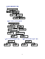
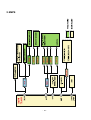
1
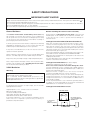
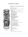
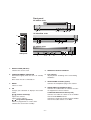
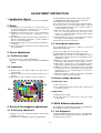
website:http://biz.LGservice.com
e-mail:http://www.LGEservice.com/techsup.html
COLOR TV
SERVICE MANUAL
CHASSIS : MC-036A
MODEL:RT-32FZ30RB
CAUTION
BEFORE SERVICING THE CHASSIS,
READ THE SAFETY PRECAUTIONS IN THIS MANUAL.
CONTENTS
CONTENTS................................................................................................2
SAFETY PRECAUTIONS ..........................................................................3
SERVICING PRECAUTIONS.....................................................................4
DESCRIPTION OF CONTROLS................................................................6
SPECIFICATION ........................................................................................9
ADJUSTMENT INSTRUCTION................................................................11
TROUBLE SHOOTING ............................................................................17
BLOCK DIAGRAM...................................................................................21
EXPLODED VIEW....................................................................................24
EXPLODED VIEW PARTS LIST ..............................................................25
REPLACEMENT PARTS LIST ................................................................26
SVC. Sheet ..................................................................................................
PRINTED CIRCUIT BOARD ........................................................................
- 2 -
SAFETY PRECAUTIONS
IMPORTANT SAFETY NOTICE
Many electrical and mechanical parts in this chassis have special safety-related characteristics. These parts are identified by
in
the Schematic Diagram and Replacement Parts List.
It is essential that these special safety parts should be replaced with the same components as recommended in this manual to
prevent X-RADIATION, Shock, Fire, or other Hazards.
Do not modify the original design without permission of manufacturer.
General Guidance
Before returning the receiver to the customer,
An isolation Transformer should always be used during
the servicing of a receiver whose chassis is not isolated from
the AC power line. Use a transformer of adequate power rating
as this protects the technician from accidents resulting in
personal injury from electrical shocks.
always perform an AC leakage current check on the exposed
metallic parts of the cabinet, such as antennas, terminals, etc.,
to be sure the set is safe to operate without damage of
electrical shock.
Leakage Current Cold Check(Antenna Cold Check)
It will also protect the receiver and it's components from being
damaged by accidental shorts of the circuitry that may be
inadvertently introduced during the service operation.
If any fuse (or Fusible Resistor) in this TV receiver is blown,
replace it with the specified.
When replacing a high wattage resistor (Oxide Metal Film
Resistor, over 1W), keep the resistor 10mm away from PCB.
Keep wires away from high voltage or high temperature parts.
Due to high vacuum and large surface area of picture tube,
extreme care should be used in handling the Picture Tube.
Do not lift the Picture tube by it's Neck.
X-RAY Radiation
Warning:
The source of X-RAY RADIATION in this TV receiver is the
High Voltage Section and the Picture Tube.
For continued X-RAY RADIATION protection, the
replacement tube must be the same type tube as specified in
the Replacement Parts List.
To determine the presence of high voltage, use an accurate
high impedance HV meter.
With the instrument AC plug removed from AC source,
connect an electrical jumper across the two AC plug prongs.
Place the AC switch in the on position, connect one lead of
ohm-meter to the AC plug prongs tied together and touch other
ohm-meter lead in turn to each exposed metallic parts such as
antenna terminals, phone jacks, etc.
If the exposed metallic part has a return path to the chassis, the
measured resistance should be between 1MΩ and 5.2MΩ.
When the exposed metal has no return path to the chassis the
reading must be infinite.
An other abnormality exists that must be corrected before the
receiver is returned to the customer.
Leakage Current Hot Check (See below Figure)
Plug the AC cord directly into the AC outlet.
Do not use a line Isolation Transformer during this check.
Connect 1.5K/10watt resistor in parallel with a 0.15uF capacitor
between a known good earth ground (Water Pipe, Conduit, etc.)
and the exposed metallic parts.
Measure the AC voltage across the resistor using AC
voltmeter with 1000 ohms/volt or more sensitivity.
Reverse plug the AC cord into the AC outlet and repeat AC
voltage measurements for each exposed metallic part. Any
voltage measured must not exceed 0.75 volt RMS which is
corresponds to 0.5mA.
In case any measurement is out of the limits specified, there is
possibility of shock hazard and the set must be checked and
repaired before it is returned to the customer.
Leakage Current Hot Check circuit
Adjust brightness, color, contrast controls to minimum.
Measure the high voltage.
The meter reading should indicate
23.5 !1.5KV: 14-19 inch, 26 !1.5KV: 19-21 inch,
29.0!1.5KV: 25-29 inch, 30.0 ! 1.5KV: 32 inch
If the meter indication is out of tolerance, immediate service
and correction is required to prevent the possibility of
premature component failure.
AC Volt-meter
To Instrument's
exposed
METALLIC PARTS
0.15uF
1.5 Kohm/10W
- 3 -
Good Earth Ground
such as WATER PIPE,
CONDUIT etc.
SERVICING PRECAUTIONS
CAUTION: Before servicing receivers covered by this service
manual and its supplements and addenda, read and follow the
SAFETY PRECAUTIONS on page 3 of this publication.
NOTE: If unforeseen circumstances create conflict between the
following servicing precautions and any of the safety
precautions on page 3 of this publication, always follow the
safety precautions. Remember: Safety First.
General Servicing Precautions
1. Always unplug the receiver AC power cord from the AC
power source before;
a. Removing or reinstalling any component, circuit board
module or any other receiver assembly.
b. Disconnecting or re-connecting any receiver electrical
plug or other electrical connection.
c. Connecting a test substitute in parallel with an electrolytic
capacitor in the receiver.
CAUTION: A wrong part substitution or incorrect
polarity installation of electrolytic capacitors may result
in an explosion hazard.
d. Discharging the picture tube anode.
2. Test high voltage only by measuring it with an appropriate
high voltage meter or other voltage measuring device (DVM,
FETVOM, etc) equipped with a suitable high voltage probe.
Do not test high voltage by "drawing an arc".
3. Discharge the picture tube anode only by (a) first connecting
one end of an insulated clip lead to the degaussing or kine
aquadag grounding system shield at the point where the
picture tube socket ground lead is connected, and then (b)
touch the other end of the insulated clip lead to the picture
tube anode button, using an insulating handle to avoid
personal contact with high voltage.
4. Do not spray chemicals on or near this receiver or any of its
assemblies.
5. Unless specified otherwise in this service manual, clean
electrical contacts only by applying the following mixture to
the contacts with a pipe cleaner, cotton-tipped stick or
comparable non-abrasive applicator; 10% (by volume)
Acetone and 90% (by volume) isopropyl alcohol (90%-99%
strength)
CAUTION: This is a flammable mixture.
Unless specified otherwise in this service manual, lubrication
of contacts in not required.
6. Do not defeat any plug/socket B+ voltage interlocks with
which receivers covered by this service manual might be
equipped.
7. Do not apply AC power to this instrument and/or any of its
electrical assemblies unless all solid-state device heat sinks
are correctly installed.
8. Always connect the test receiver ground lead to the
receiver chassis ground before connecting the test receiver
positive lead.
Always remove the test receiver ground lead last.
9. Use with this receiver only the test fixtures specified in this
service manual.
CAUTION: Do not connect the test fixture ground strap to
any heatsink in this receiver.
Electrostatically Sensitive (ES) Devices
Some semiconductor (solid state) devices can be damaged
easily by static electricity. Such components commonly are
called Electrostatically Sensitive (ES) Devices. Examples of
typical ES devices are integrated circuits and some field-effect
transistors and semiconductor "chip" components. The
following techniques should be used to help reduce the
incidence of component damage caused by static by static
electricity.
1. Immediately before handling any semiconductor component
or semiconductor-equipped assembly, drain off any
electrostatic charge on your body by touching a known earth
ground. Alternatively, obtain and wear a commercially
available discharging wrist strap device, which should be
removed to prevent potential shock reasons prior to
applying power to the unit under test.
2. After removing an electrical assembly equipped with ES
devices, place the assembly on a conductive surface such as
aluminum foil, to prevent electrostatic charge buildup or
exposure of the assembly.
3. Use only a grounded-tip soldering iron to solder or unsolder
ES devices.
4. Use only an anti-static type solder removal device. Some
solder removal devices not classified as "anti-static" can
generate electrical charges sufficient to damage ES devices.
5. Do not use freon-propelled chemicals. These can generate
electrical charges sufficient to damage ES devices.
6. Do not remove a replacement ES device from its protective
package until immediately before you are ready to install it.
(Most replacement ES devices are packaged with leads
electrically shorted together by conductive foam, aluminum
foil or comparable conductive material).
7. Immediately before removing the protective material from
the leads of a replacement ES device, touch the protective
material to the chassis or circuit assembly into which the
device will be installed.
CAUTION:Be sure no power is applied to the chassis or
circuit, and observe all other safety precautions.
8. Minimize bodily motions when handling unpackaged
replacement ES devices. (Otherwise harmless motion such
as the brushing together of your clothes fabric or the lifting
of your foot from a carpeted floor can generate static
electricity sufficient to damage an ES device.)
General Soldering Guidelines
1. Use a grounded-tip, low-wattage soldering iron and
appropriate tip size and shape that will maintain tip
temperature within the range or 500cF to 600cF.
2. Use an appropriate gauge of RMA resin-core solder
composed of 60 parts tin/40 parts lead.
3. Keep the soldering iron tip clean and well tinned.
4. Thorohly clean the surfaces to be soldered. Use a mall
wirebristle (0.5 inch, or 1.25cm) brush with a metal handle.
Do not use freon-propelled spray-on cleaners.
5. Use the following unsoldering technique
a. Allow the soldering iron tip to reach normal temperature.
(500cF to 600cF)
b. Heat the component lead until the solder melts.
c. Quickly draw the melted solder with an anti-static,
suction-type solder removal device or with solder braid.
CAUTION: Work quickly to avoid overheating the circuitboard printed foil.
6. Use the following soldering technique.
a. Allow the soldering iron tip to reach a normal
temperature (500cF to 600cF)
b. First, hold the soldering iron tip and solder the strand
against the component lead until the solder melts.
- 4 -
c. Quickly move the soldering iron tip to the junction of the
component lead and the printed circuit foil, and hold it
there only until the solder flows onto and around both the
component lead and the foil.
CAUTION: Work quickly to avoid overheating the circuit
board printed foil.
d. Closely inspect the solder area and remove any excess
or splashed solder with a small wire-bristle brush.
IC Remove/Replacement
Some chassis circuit boards have slotted holes (oblong) through
which the IC leads are inserted and then bent flat against the
circuit foil. When holes are the slotted type, the following
technique should be used to remove and replace the IC. When
working with boards using the familiar round hole, use the
standard technique as outlined in paragraphs 5 and 6 above.
Removal
1. Desolder and straighten each IC lead in one operation by
gently prying up on the lead with the soldering iron tip as the
solder melts.
2. Draw away the melted solder with an anti-static suctiontype solder removal device (or with solder braid) before
removing the IC.
Replacement
1. Carefully insert the replacement IC in the circuit board.
2. Carefully bend each IC lead against the circuit foil pad and
solder it.
3. Clean the soldered areas with a small wire-bristle brush.
(It is not necessary to reapply acrylic coating to the areas).
"Small-Signal" Discrete Transistor
Removal/Replacement
1. Remove the defective transistor by clipping its leads as
close as possible to the component body.
2. Bend into a "U" shape the end of each of three leads
remaining on the circuit board.
3. Bend into a "U" shape the replacement transistor leads.
4. Connect the replacement transistor leads to the
corresponding leads extending from the circuit board and
crimp the "U" with long nose pliers to insure metal to metal
contact then solder each connection.
Power Output, Transistor Device
Removal/Replacement
1. Heat and remove all solder from around the transistor leads.
2. Remove the heatsink mounting screw (if so equipped).
3. Carefully remove the transistor from the heat sink of the
circuit board.
4. Insert new transistor in the circuit board.
5. Solder each transistor lead, and clip off excess lead.
6. Replace heatsink.
Diode Removal/Replacement
1. Remove defective diode by clipping its leads as close as
possible to diode body.
2. Bend the two remaining leads perpendicular y to the circuit
board.
3. Observing diode polarity, wrap each lead of the new diode
around the corresponding lead on the circuit board.
4. Securely crimp each connection and solder it.
5. Inspect (on the circuit board copper side) the solder joints of
the two "original" leads. If they are not shiny, reheat them
and if necessary, apply additional solder.
Fuse and Conventional Resistor
Removal/Replacement
1. Clip each fuse or resistor lead at top of the circuit board
hollow stake.
2. Securely crimp the leads of replacement component around
notch at stake top.
3. Solder the connections.
CAUTION: Maintain original spacing between the replaced
component and adjacent components and the circuit board
to prevent excessive component temperatures.
Circuit Board Foil Repair
Excessive heat applied to the copper foil of any printed circuit
board will weaken the adhesive that bonds the foil to the circuit
board causing the foil to separate from or "lift-off" the board.
The following guidelines and procedures should be followed
whenever this condition is encountered.
At IC Connections
To repair a defective copper pattern at IC connections use the
following procedure to install a jumper wire on the copper
pattern side of the circuit board. (Use this technique only on IC
connections).
1. Carefully remove the damaged copper pattern with a sharp
knife. (Remove only as much copper as absolutely
necessary).
2. carefully scratch away the solder resist and acrylic coating
(if used) from the end of the remaining copper pattern.
3. Bend a small "U" in one end of a small gauge jumper wire and
carefully crimp it around the IC pin. Solder the IC connection.
4. Route the jumper wire along the path of the out-away
copper pattern and let it overlap the previously scraped end
of the good copper pattern. Solder the overlapped area and
clip off any excess jumper wire.
At Other Connections
Use the following technique to repair the defective copper
pattern at connections other than IC Pins. This technique
involves the installation of a jumper wire on the component
side of the circuit board.
1. Remove the defective copper pattern with a sharp knife.
Remove at least 1/4 inch of copper, to ensure that a
hazardous condition will not exist if the jumper wire opens.
2. Trace along the copper pattern from both sides of the
pattern break and locate the nearest component that is
directly connected to the affected copper pattern.
3. Connect insulated 20-gauge jumper wire from the lead of
the nearest component on one side of the pattern break to
the lead of the nearest component on the other side.
Carefully crimp and solder the connections.
CAUTION: Be sure the insulated jumper wire is dressed so
the it does not touch components or sharp edges.
- 5 -
DESCRIPTION OF CONTROLS
All the functions can be controlled with the remote control handset.
Some functions can also be adjusted with the buttons on the front
panel of the set.
Remote control handset
Before you use the remote control handset, please install the batteries. See the next page.
POWER
MUTE
11 1. POWER
switches the set on from standby or off to standby.
1
1
2
3
4
5
6
7
8
9
ARC
0
TV/AV
PICTURE
MENU
2. NUMBER BUTTONS
switches the set on from standby or directly select a number.
2
3. ARC (Aspect Ratio Control)
changes the picture format.
12 4. TURBO SOUND BUTTON
selects Turbo sound.
13
TURBO PICTURE BUTTON
selects Turbo picture.
14
5. D / E (Programme Up/Down)
selects a programme or a menu item.
switches the set on from standby.
F / G (Volume Down/Up)
adjusts the volume.
adjusts menu settings.
3
SOUND
4
OK
T U R B O
PR
5
6
VOL
VOL
PR
REW
PLAY
FF
P/STILL
STOP
REC
6. VCR BUTTONS
control a LG video cassette recorder.
7
8
9
I/II
SSM
PSM
SLEEP
TEXT
PIP
LIST
15 7. SSM (Sound Status Memory)
recalls your preferred sound setting.
16
17 8. I/II
18
selects the language during dual language broadcast.
19
selects the sound output (option).
EYE/
Q.VIEW
10
MIX
TIME
REVEAL ? MODE M
SIZE
STILL
POSITION
PR
PR
SCAN
SWAP
i
INPUT
9. PSM (Picture Status Memory)
recalls your preferred picture setting.
10. TELETEXT BUTTONS (option)
These buttons are used for teletext.
For further details, see the ‘Teletext’ section.
11. MUTE
switches the sound on or off.
12. TV/AV
selects TV or AV mode.
switches the set on from standby.
(With PIP)
13. MENU
selects a menu.
14. OK
accepts your selection or displays the current mode.
- 6 -
15. LIST
displays the programme table.
16. EYE/ (option)
switches the eye function on or off.
*
17. SLEEP
sets the sleep timer.
18. Q.VIEW
returns to the previously viewed programme.
selects a favourite programme.
POWER
MUTE
11
1
19. PIP BUTTONS (option)
PIP
2
switches the sub picture on or off.
PR +/selects a programme for the sub picture.
SWAP
3
alternates between main and sub picture.
INPUT
4
selects the input mode for the sub picture.
SIZE
adjusts the sub picture size.
STILL
5
freezes motion of the sub picture.
POSITION
relocates the sub picture in clockwise direction.
SCAN
6
switches on or off the programme scan mode through 12 sub
pictures.
20. STILL
7
freezes motion of the picture.
8
COLOURED BUTTONS : These buttons are used for teletext (only 9
TELETEXT models) or programme edit.
10
1
2
3
4
5
6
7
8
9
ARC
0
TV/AV
PICTURE
MENU
12
SOUND
13
T U R B O
OK
14
PR
VOL
VOL
PR
REW
PLAY
FF
P/STILL
STOP
REC
I/II
SSM
PSM
SLEEP
TEXT
LIST
EYE/
Q.VIEW
MIX
TIME
REVEAL ? MODE M
SIZE
STILL
UPDATE
15
16
17
18
INDEX i
20
(Without PIP)
- 7 -
Front panel
RT-29FB91 series
1
2 3
5
4
6
RT-28/32FZ30 series
7
S-VIDEO
ON/OFF
VOL
3
4
PR
VIDEO
MENU OK
L/MONO AUDIO R
8
1 25
6
RT-29FA34 series
AV3
MENU
OK
VOL
PR
ON/OFF
Side panel
23
1
RT-32FZ60 series
4
5
7
2 3
1
1. MAIN POWER (ON/OFF)
switches the set on or off.
6
8
4
5
5. REMOTE CONTROL SENSOR
2. POWER/STANDBY INDICATOR
illuminates brightly when the set is in standby
mode.
dims when the set is switched on.
6. EYE (option)
adjusts picture according to the surrounding
conditions.
7. HEADPHONE SOCKET (option)
Connect the headphone plug to this socket.
3. MENU
selects a menu.
4. OK
accepts your selection or displays the current
mode.
F / G (Volume Down/Up)
adjusts the volume.
adjusts menu settings.
D / E (Programme Up/Down)
selects a programme or a menu item.
switches the set on from standby.
8. AUDIO/VIDEO IN SOCKETS (AV3)
Connect the audio/video out sockets of external equipment to these sockets.
S-VIDEO/AUDIO IN SOCKETS (S-AV)
Connect the video out socket of an S-VIDEO
VCR to the S-VIDEO socket.
Connect the audio out sockets of the S-VIDEO
VCR to the audio sockets as in AV3.
- 8 -
SPECIFICATION
NOTE : Specifications and others are subject to change without notice for improvement.
F Scope
This specification can be applied to all the television related to
MC-036A Chassis.
F Test Condition
F Test and Inspection Method
1) performance:Follow the Standard of LG TV test
2) Standards of Etc requirement
Compliance
Safety: IEC60065
EMC: EN55020,EN55013
1) Temperature :20±5°C
2) Relative Humidity:65±10%
3) Use the parts only designated in B.O.M.,PARTS SPEC.,or
drawings.
4) Follow each drawing or spec for spec and performance of
parts,based upon P/N of B.O.M
5) Warm up TV set for more than 20min. before the
measurement.
F General Specification
Item
No
1
Receiving System
Specification
Remark
PAL,SECAM-BG
PAL/SECAM DK, PAL I/I
2
AV Receiving System
SECAM-L/L’
OPTION
NTSC M
NON EU
1) NTSC M
2) PAL
3) SECAM
3
Available Channel
1) VHF:E2~E12
2) UHF:E21~E69
3) CATV:S1~S20
4) HYPER:S21~S41
4
Input Voltage
110-240V~, 50/60 Hz
5
Market
MIDDLE EAST, AFRICA
6
Screen Size
Flat 29”, Wide 28” / 32”
7
Tuning System
FVS 100Program
8
Operating Environment
1) Temp : 0 ~ 40 deg
2) Humidity: 85% under
9
Storage Environment
1) Temp : -20 ~ 60 deg
2) Humidity: 85% under
- 9 -
NON EU
Flat / Wide
F Feature and Function
No
Item
Specification
Remark
Option
1
Teletext
TOP, FLOF, LIST 8page
2
Remocon
NEC code
3
AV input
3
Side or, Front: 1, Rear: 2
4
Component input
480I
Option(RT- MODEL)
5
PERI TV connector
Full SCART:1
AV1
6
RGB input
1
AV1
7
2 Carrier stereo
BG,DK
8
NICAM stereo
BG,I
9
2 Carrier Dual
BG,DK
10
NICAM Dual
BG,I
11
SSC(Split Screen) mode
X
12
Multi picture display mode(1,2,12 PIP)
PAL. BG.I, DK, M
13
Film mode
X
14
Noise reduction
X
15
Progressive scan
X
16
Motion detection
X
17
DBS
O
18
Swivel speaker
X
19
Digital eye
O
Option(RT- MODEL)
Max.: PSM (Dynamic)
Min.: PSM (Mild)
- 10 -
ADJUSTMENT INSTRUCTION
(3) Self-adjustment: Adjust by input of Green raster signal
Manual-adjustment: Receive the signal of red raster.
(RF: PG50Ch or A/V input: RED pattern)
(4) Loosen fixed screw of DY and closely to CPT funnel part.
(5) Check the center of screen that purity magnet of CPT by
crossing adjustment. At this time, 4 & 6 pole magnet is
located to magnet of nothing.
(6) Move the DY to make equal red on whole screen and it
does not to make the DY by fixed screw after check a
simple color of Red/Green/Blue and white raster whether
or not it is a pollution of color.
(At this time, take care raster of screen and DY must fixing in
the condition which maintains a horizontality.)
(7) Check the TV set by move direction.
1. Application Object
These instructions are applied to all of the color TV, MC-036A.
2. Notes
(1) Because this is not a hot chassis, it is not necessary to use
an isolation transformer. However, the use of isolation
transformer will help protect test instrument.
(2) Adjustment must be done in the correct order.But the
adjustment can be changed by consideration of mass
production.
(3) The adjustment must be performed in the circumstance of
25±5°C of temperature and 65±10% of relative humidity if
there is no specific designation.
(4) The input AC voltage of the receiver must keep 220V±10%
in adjusting.
(5) The receiver must be operated for about 15 minutes prior
to the adjustment.
4-2. Convergence adjustment
These adjustments can the best condition of focus after
finished purity adjustment.
(1) Receive the signal of cross hatch that color is black.
(2) Adjust brightness and luminosity till dot appear 9 ~12.
(3)Open angle of the two tab of 4 pole magnet by isogonic
angle and accord with vertical line of red and blue color in
the middle of screen.
(4)Maintain as angle of 3) and rotate the tab to accord with
vertical line of Red and Blue color in the middle of screen.
(5) Open angle of the two tab of 6 pole magnet by isogonic
angle and accord with vertical line of Red/Blue and Green.
(6) Maintain as angle of 5) and rotate the tab to accord with
horizontal line. In case of twisted horizontal line,repeat
adjustment of 3) ~ 5) remembering the movement of
Red/Green/Blue color.
(7) Move the DY to best condition of convergence and attach
the CPT to a rubber-chock for fixed DY.
3. Focus adjustment
3-1. Preliminary steps
(1) Tune the TV set to receive a digital pattern.
(SVC mode: Automatically mode change the STANDARD
MODE)
3-2. Adjustment
(1) Adjust center focus volume of FBT for the best focus of
vertical line (B).
(2) Adjust the upper focus volume of FBT for the best focus of
area (A).
(3) Repeat above step 1) and 2) for the best overall focus.
4-3 Screen voltage adjustment
1) Preliminary steps
(1) Turn on the TV set.
(2) This adjustment should be performed after warming up for
more than 15 minutes.
2) Adjustment
(1) Adjust in RF non-signal.
(2) Press the ADJ key of SVC remote controller to make
horizontal line.
5. White balance adjustment
This adjustment should be performed after screen adjustment.
This adjustment set the self-adjustment rule.
4. Purity & Convergence adjustment
4-1. Color purity adjustment
5-1. Test Equipment
(1) Magnetic room set to destination magnetic and horizontal
magnetic set to zero.
(2) It makes CPT or CABINET enough to demagnetization.
- 11 -
(1) Automatic White balance meter: Incase of self-adjustment
(2) White balance meter(CRT Color Analyzer, CA-100): 1 EA
(3) A SVC remote controller.
5-2. Preliminary steps
(1) Tune the TV set to receive an 100% white pattern.
(2) This adjustment should be performed after screen voltage
adjustment.
g.Repeat adjusting until the color coordinate of High and
Low Light is satisfied.
h.Check the color coordinate of adjusted condition with
white balance meter.
5-3. Adjustment
(1) Press the CH D ,E key to select adjustment item.
(2) Press the VOL F ,G key to change data.
(3) Adjustment preliminary steps.
a.In items of picture adjustment,adjust until “CONTRAST”
and “BRIGHT” become 45 Ft_L(153Cd/m2).
b. Press the SVC key to enter adjustment mode.
c. Adjust the Y value of High Light with R-DRIVE and
adjust the X value with B-DRIVE until they have the
color coordinate of High Light as below.
d. In items of picture adjustment,adjust until “CONTRAST”
and “BRIGHT” become 4.5 Ft_L(15.4FT-L).
e. Enter the adjustment mode by pressing the SVC key.
f. Adjust the Y value of Low Light with R-CUTOFF and
adjust the X value with B-CUTOFF until they have the
color coordinate of Low Light as below.
Color temperature. X coordinate Y coordinate
Remark
Non EU(except model)
13000K
266 ± 8
273 ± 8
EU (RE,RL model)
9000K
288 ±8
295 ± 8
SERVICE1
PH 32” FLAT SS 29” FLAT SS 28” FLAT
Item
256
256
256
CR(0~511)
256
256
256
CG(0~511)
256
256
256
CB(0~511)
256
256
256
WR(0~511)
256
256
256
WG(0~511)
256
256
256
WB(0~511)
20
20
20
SBRI(-255 ~ 254)
-2
-2
-2
YCDEL
Remark
LOW LIGHT adjustment
LOW LIGHT adjustment
LOW LIGHT adjustment
HIGH LIGHT adjustment
HIGH LIGHT adjustment
HIGH LIGHT adjustment
SUB BRIGHT adjustment
IIC DATA SETTING
OFFSE DATA
IIC WRITE
SUB ADD
START BIT
STOP BIT
R AMP
0
R CUT
3
B AMP
1
B CUT
2
1C8
8
0
1C3
8
0
1CA
8
0
1C5
8
0
30,31
2A,2B
34,35
2E,2F
EEPROM
SUB ADD
SLAVE ADDRESS(WRITE)
IC
8A EEPROM A0
SUB BRIGHT CONTROL DATA
SPEED
2
- 12 -
SUB BRIGHT
DATA SAVE
6.Deflection & POP position setting
data adjustment.
6.1 Adjustment preparation
(1) Deflection setting data adjustment is operate by SVC
communicator.
(2) Enter the adjustment mode by pressing SVC key.
(3) Enter the deflection mode by pressing ADJUST key.
(4) Use the CH D ,E key to select adjustment item.
(5) Use the VOL F ,G key to increase/decrease data.
(6) Tune the TV set to receive PAL-B/G Digital pattern.
bottom ,right-bottom of screen to the best straight line.
(15) OSD P (OSD POSITION) adjustment.
Adjust so that the character “2” of “EHTP2” is in accord with
right of Screen Center Vertical line after finished (1)~ (14)
adjustment. ( Refer to <figure.1> and <figure.2>.)
6.2 Adjustment
(1) VL(Vertical Linearity) adjustment:
Adjust the top & bottom size of inner circle to be equal.
(2) VA (Vertical Amplitude) adjustment:
Adjust so that the circle of a digital circle pattern should be
located interval of 6~7mm from the effective screen of the
CPT.
(3) SC (Vertical S correction) adjustment:
Adjust so that all distance between each lattice width of
top/center/bottom are to be the same.
(4) VS (Vertical Shift) adjustment:
Adjust so that the geometric vertical center line is in accord
with vertical center line of CPT.
(5) HS(Horizontal Shift) adjustment:
Adjust so that the geometric horizontal center line is in
accord with horizontal center line of CPT.
(6) EW(East-West Width) adjustment:
Adjust until the outmost left and right lattice of received
pattern is accord with 75% of other lattice width.
(7) ET(East-West Trapezium) adjustment:
Adjust to make the length of top horizontal line same with it
of the bottom of horizontal line.
(8) EP (East-West Parabola) adjustment:
Adjust so that middle portion of the outermost left and right
vertical line look like parallel with vertical lines of the CPT.
(9) CRNU(Upper Corner Correction) adjustment:
After finished EP adjustment,adjust vertical line of lefttop,right-top of screen to the best straight line.
(10)CRNL(Lower Corner Correction) adjustment:
After finished EP adjustment,adjust vertical line of leftbottom ,right-bottom of screen to the best straight line.
(11) BOW adjustment
A standard is not changing the default value.
(12) Angle adjustment.
When you adjust the angle,adjust correctly raster of
left/right screen.
(13) CRNU6(6’ th Order Upper Corner Correction) adjustment
After finished EP adjustment,adjust vertical line of lefttop,right-top of screen to the best straight line.
(14) CRNL6( Lower Corner Correction) adjustment:
After finished EP adjustment,adjust vertical line of left-
- 13 -
<figure.1>
<figure.2>
SERVICE 2 standard DATA
Item
VL
VA
SC
VS
HS
EW
ET
EP
CRNU
CRNL
BOW
ANGLE
CRNU6
CRNL6
EHTTH
EHT
EHTV1
EHTV2
EHTH1
EHTH2
EHT F
EHTP1
EHTP2
OSD P
Variable
range
-128~127
-128~127
-128~127
-256~255
-512~511
-256~255
-128~127
-256~255
-128~127
-128~127
-512~511
-512~511
-128~127
-128~127
0~2047
0~511
-512~511
-512~511
-512~511
-512~511
0~511
-511~512
-511~512
-15~15
PHILIPS
32”FLAT
0
10
20
0
-152
5
0
234
4
5
2
1
-1
-1
250
60
-61
-20
-97
-22
0
-20
-40
0
S/S
29” FLAT
0
19
30
5
-198
-13
0
228
6
6
0
0
-1
-1
250
60
-61
-20
-97
-22
0
-20
-40
0
S/S
28” FLAT
0
49
20
0
-180
0
0
239
2
3
0
0
-1
-1
250
60
-61
-20
-97
-22
0
-20
-40
0
SERVICE 3 standard DATA
Item
IBRM
WDRM
CGAIN
WGAIN
MWDR
BCLTH
BCLTC
BCLGA
BCLC
SVDEL
SVD
SVG
VBSO
TML
PHILIPS
32”FLAT
413
128
50
50
496
85
400
113
200
7
4
30
23
14
S/S
29” FLAT
413
128
50
50
496
140
400
230
200
5
4
30
23
15
Screen OSD FONT status and adjustment in H-Shift ARC
SVC adjustment.
S/S
28” FLAT
413
128
50
50
496
135
400
200
200
5
4
20
23
14
No. ARC MODE SVC OSD FONT(50Hz,PAL)
1
16:9
50W
2
14:9
50 149
3
ZOOM1
50 Z1
4
ZOOM2
50 Z2
5
4:3
50 N
Deflection adjustment standard DATA
Item
SERVICE 4 standard DATA
Item
FP
NP
SP
S1 VOL
S2 VOL
AGC-L
VPC-L
M-STR
M-HMC
M-HP
M-LP
M-LIM
PHILIPS
32”FLAT
20
83
17
102
102
230
0
45
25
9
11
252
S/S
29” FLAT
20
83
17
102
102
230
0
45
25
9
11
252
H-SHIFT
Adjustment
Adjustment
Adjustment X
Adjustment X
Adjustment
S/S
28” FLAT
20
83
17
102
102
230
0
45
25
9
11
252
29” Model:
Adjustment must adjust to the N50Hz(Only PAL mode).
W50Hz,N60Hz and W60Hz need not adjustments.(Only 29”
model)
28”/32” WIDE Model:
14:9,4:3 MODE H-SH(H-SHIFT) adjustment addition.
Adjust “H-SHIFT” of 14:9 and 4:3 by 50Hz.
* Caution: Adjustment of 50 Hz is 16:9’s standard format.
When the adjustment is 50Hz wide mode, you must be done
re-check.
At this time, ZOOM1 and ZOOM2 Mode need not
adjustments. Because it can automatically correct in 16:9
mode.
When you want to re-adjust after deflection adjustment,
adjustment is finished after always re-adjustment.
- 14 -
VL
VA
SC
VS
HS
EW
ET
EP
CRNU
CRNL
BOW
ANGLE
CRNU6
CRNL6
PFGHE
PFGHB
EHTTH
EHTS
EHTV1
EHTV2
EHTH1
EHTH2
EHT F
EHTP1
EHTP2
OSD P
Variable
range
-128~127
-128~127
-128~127
-256~255
-512~511
-256~255
-128~127
-256~255
-128~127
-128~127
-512~511
-512~511
-128~127
-128~127
0~1024
0~1024
0~2047
0~511
-512~511
-512~511
-512~511
-512~511
0~511
-511~512
-511~512
-15~15
PAL
100Hz
0
10
20
0
-152
5
0
234
4
5
2
1
-1
-1
0
0
250
60
-61
-20
-97
-22
0
-20
-40
0
480I
0
10
20
0
-152
5
0
234
4
5
2
1
-1
-1
0
0
250
60
-61
-20
-97
-22
0
-20
-40
0
Adjust in PAL100Hz and PAL50Hz,NTSC60Hz and 480I
needed not adjustment.
Table 2. OPTION 2 Function
7. OPTION Adjustment
Option Code
7-1. Preparation for Adjustment
ACMS
1) This option adjustment decides function in accordance with
model.
Press the SVC TX adjustment button(IN-START button) at
SVC mode,then adjust the option at OPTION 1,2,3,4 mode.
2) Mark the option adjustment data like [111,11,111,11] in BOM.
VOL
HPHON
[63,56,112,201]
D
D D D
DVD
OPTION 1
OPTION 2
OPTION 3
OPTION 4
O
SAV3
WOOF
Mark of BOM
Function
0
Without ACMS function
1
With ACMS function
0
Normal volume curve
EU
1
Rushed volume curve
NON EU
0
Without headphone
1
With headphone
0
Without DVD input
1
With DVD input
0
AV3 Y&C not coresspondence
1
AV3 Y&C coresspondence
0
Without woofer
1
With woofer
0
LEVEL PART NO.
1. 3141VMN382A
SPECIFICATION
DESCRIPTION
MAIN[63.56.112.201]
CHASSIS ASSY
RESE1
AV SV
The OPTION 1 data is 113,OPTION 2 data is 63,the
oOPTION 3 data is 112,the OPTION 4 data is 201 in this
model.
Option
WIDE
1) Input data directly by the buttons corresponded with
OPTION1 ??(0~63), OPTION2 ??(0~63), OPTION3
???(0~127).
2) Option4???(0~116) controls corresponding lines directly
relate with OSD and TXT LANG.
3) Select each OPTION function by the CH Up/Down button and
then set up each OPTION by the VOL Up/Down button.
200PR
TSEAR
I II SV
TOP
EYE
A2 ST
SYS
Function
TEXT
CH+AU
HEDV
Table.1 OPTION 1 Function
Code
Remark
DOLBY
0
100 PROGRAM SAVE
1
200 PROGRAM SAVE
0
WITHOUT TURBO SEARCH FUNCTION
WL/CL model
1
WITH TURBO SEARCH FUNCTION
CT/CE/WT/WE model
0
NO SAVE DUAL SOUND CONDITION
EU(WE/WL/CE/C model)
1
SAVE DUAL SOUND CONDITION
NON-EU (WT/CT model)
0
FLOP TEXT
Without top text
1
TOP TEXT
0
WITHOUT EYE
1
WITH EYE
0
FM STEREO/DUAL NON ACTIVE
1
NICAM AND FM STEREO/DUAL
0
BG/I/DK
1
BG/L
2
BG/I/DK/M
3
RESERVED
Australia
NON USED
1
0
No save last AV
1
Last AV save
Table. 3 OPTION 3 Function
7-2. Adjustment Method
Option
Remark
Function
Code
0
4:3 TV
1
16:9 TV
0
WITHOUT TEXT
1
WITH TEXT
0
WITHOUT D/K CHINA or BB SYSTEM
1
WITH D/K CHINA or BB SYSTEM
0
WITHOUT HIGH DEVIATION
1
WITH HIGH DEVIATION
0
WITHOUT DOLBY VIRTUAL
1
WITH DOLBY VIRTUAL
Remark
High deviation
NON USED
RESE3
HOTEL
- 15 -
0
WITHOUT HOTEL FUNCTION
1
WITH HOTEL FUNCTION
NON USED
RESE2
Table 4. OPTION 4 Function
State
LANG
Language
Function
0:ENG Only
English
1:EU 5EA
English/German/French/Italy/Spanish
2:EU ETC
Netherlands/Sweden/Norway/Denmark/Pinland/Portugal/Rumania/Poland
/Hungary/Czech/Russia
3:GREECE
LANG
(NON EU)
T-LAN
0:ENG Only
English
1:PARSI
English/Farsi
2:ARAB URDU
English/French/Arab/Urdu
0:West EU
English/French/Swedish/Czech/German/Spanish/Italian
1:East EU1
Polish/French/Swedish/Czech/German/Slovenian/Italian/Rumanian
2:Turkey EU1
English/French/Swedish/Turkish/German/Spanish/Italian
3:East EU2
English/Czech/Hungarian/Serbian/German/Polish/Turkish/Rumanian
4:Cyrillic 1
Polish/Russia/Estonian/Swedish
5:Cyrillic 2
Polish/Russia/Swedish/Czech/Estonian
6:Cyrillic 3
English/Russia/Estonian/Czech/German/Ukrainian
7:Turkey/Greek 1
English/French/Swedish/Turkish/German/Spanish/Italian/Greek
8:Turkey/Greek 2
English/Turkish/German/Turkish/Greek
9:Turkey/Greek 3
English/French/Swedish/Turkish/German/Spanish/Italian/Greek
10:Arab/France
English/French/English/Arabic
11:Arab/English
English/French/Turkish/Arabic
12:Arab/Hebrew 1
Hebrew/Arabic
13:Arab/Hebrew 2
English/French/Hebrew/Arabic
14:Farsi/English
English/French/Turkish/Farsi
15:Farsi/France
French/Turkish/Farsi
16:Farsi all
MAX V
Max Volume
* MSP3410 Pre-scaler setting value.
8. Sound Pre scaler
Don’t adjust mass-production. Because this value of SVC
setting is set to come up to standard. Only This standard is for
reference.
Description
Item
DATA
FP
FM Pre-scaler
21
90
NP
Nicam Pre-scaler
In case of Phone jack is over 1EA in AV1 & AV2,apply to
Phone standard.
- Audio out level: 500mVrms at 100% modulation ratio.
SP
Scart Pre-scaler
20
S1 vol
Scart1 Pre-scaler
102
S2 vol
Scart2 Pre-scaler
102
In case of both of AV1 & AV2 is Scart jack,apply to Scart jack
standard.
- Audio out level 500Vrms at 54% modulation ratio
VPC-L
VPC LEVEL
0
M-STR
EFFECT STRENGTH
45
M-HMC
HARMONIC CONTENT
25
M-HP
HIGH PASS CENTER FREQUENCY
9
M-LP
LOW PASS CENTER FREQUENCY
11
M-LIM
AMPLITUDE LIMIT
252
- 16 -
TROUBLE SHOOTING
- 17 -
- 18 -
- 19 -
- 20 -
BLOCK DIAGRAM
1.MAIN
- 21 -
2.SMPS
- 22 -
MEMO
- 23 -
EXPLODED VIEW
943
400
913
170
510
150
112
503
550
560
122
590
520
501
580
300
121
120
310
122
330
320
600
315
- 24 -
EXPLODED VIEW PARTS LIST
No.
PART NO.
112
2440GE489AS
WVT SET, W76QDD259X V8N7ND
120
6400VA0025B
SPEAKER,FULLRANGE C163P02K1450 8OHM 15/20W 85DB OTHERS 57X160X52.5
121
120-C76G
SPEAKER,TWEETER C050TX-357K14 FOSTER 8OHM 15/25W 88DB OTHERS NON
122
4810V00689A
BRACKET, SPEAKER RN-32FZ30 MC021A ABS, HF-380
150
6140VC2006A
COIL,DEGAUSSING KOREA TRADING 32” TURN L=600
170
170-797X
300
3091V00B57R
CABINET ASSEMBLY, RT-32FZ30RB STEREO MC036A SCART(84B)
310
5020V00775B
BUTTON, CONTROL DN-32FZ33H ABS, HI-153 6KEY #84B
315
3580V00084D
DOOR, CONTROL RE-32FZ30RX ABS, HF-380
320
320-062E
330
5020V00728B
BUTTON, POWER DN-32FZ32H ABS, HF-380 1KEY #102”
400
3809V00A93K
BACK COVER ASSEMBLY, RT-32FZ30RB(W EARPHONE) 1SCART 1PHONE MC036A
501
4810V00684D
BRACKET, MAIN RE-32FZ30RQ MC036A HIPS 407AF V2
503
4811V00024J
BRACKET ASSEMBLY, REAR AV RE-32FZ30RX PHONE+SCART MC036A .
510
6871VSMZ52B
PWB(PCB) ASSEMBLY,SUB, CPT MC036A RT-32FZ60RB.AHLLKG LG32”
520
6871VMMT03C
PWB(PCB) ASSEMBLY,MAIN MC036A RT-32FZ30RB.ALLLKR M/I
530
6871VSMW05A
PWB(PCB) ASSEMBLY,SUB CONT MC036A FRONT CTRL RE32FZ30RX
540
6871VSMW04A
PWB(PCB) ASSEMBLY,SUB CONT MC036A POWER CTRL RE32FZ30RX
550
6871VSMW22A
PWB(PCB) ASSEMBLY,SUB SUB MC036A REACTOR SUB
560
6871VSMZ65M
PWB(PCB) ASSEMBLY,SUB SUB MC036A RT-32FZ30RB(W/ PIP, EYE(3P), E-P)
600
6871VSMW03B
PWB(PCB) ASSEMBLY,SUB A/V MC036A RT-29FB91RB.ATLLKX
700
0IGL120104A
IC,LG SEMICONDUCTOR” CDS SENSOR MODULE(P1201-04)
913
332-229M
SCREW,DRAWING PAN WASHER 7mm 45mm MSWR3 / FZY
943
1PTF0403116
SCREW TAP TITE(P),TRUSS HEAD + D4.0 L16.0 MSWR3/FZB
DESCRIPTION
CPT EARTH, 32” 144T 2LUG 1P*2
SPRING, KNOB
- 25 -
REPLACEMENT PARTS LIST
LOCA. NO
PART NO
DESCRIPTION
LOCA. NO
PART NO
Q164
0TR733009AA
KSA733C-Y TP TO-92
Q165
0TR945009AA
KSC945C-Y TP TO92 50V 150MA
Q166
0TR733009AA
KSA733C-Y TP TO-92
Q167
0TR733009AA
KSA733C-Y TP TO-92
IC
DESCRIPTION
D850
0ISK100300A
SLA1003 SIP12 BK
IC002
0IAL241610B
AT24C16A-10PI-2.7 8PIN DIP ST
IC003
0IPH743200A
74HC32D 14SOP TP QUAD 2-INPUT OR GATE
Q168
0TR945009AA
KSC945C-Y TP TO92 50V 150MA
IC012
0IFA754207A
KA75420ZTA(KA7542ZTA) 3P,TO-92 TP 4.2V
Q200
0TR733009AA
KSA733C-Y TP TO-92
IC013
0IFA752700A
KA75270Z 3 TP RE-SET IC MC-007
Q240
0TR387500AA
CHIP 2SC3875S(ALY) KEC
IC014
0IMCRUK002B
S78DL33L AUK 3P, TO-92L TP 3.3V REGU.
Q242
0TR387500AA
CHIP 2SC3875S(ALY) KEC
IC015
0IMCRUK003A
S5225M AUK 5SOP, SOT-25
Q243
0TR387500AA
CHIP 2SC3875S(ALY) KEC
IC016
0IAL241610B
AT24C16A-10PI-2.7 8PIN DIP ST EEPROM
Q244
0TR387500AA
CHIP 2SC3875S(ALY) KEC
IC101S
0IMCRMN022B
VSP9417B VK C4 80P MQFP
Q245
0TR387500AA
CHIP 2SC3875S(ALY) KEC
IC102
0IMCRSG011A
LD1086V18 3DIP,TO-220 ST 1.5A-L/DROP REG
Q246
0TR387500AA
CHIP 2SC3875S(ALY) KEC
IC102S
0ISO204000A
CXA2040AQ 32P,QFP BK IIC BUS VIDEO S/W
Q246
0TR387500AA
CHIP 2SC3875S(ALY) KEC
IC103
0IMCRSG011A
LD1086V18 3DIP,TO-220 ST 1.5A-L/DROP REG
Q2902
0TR319809AA
KTC3198(KTC1815) TP TO92 50V 150MA
IC104
0ISG111733B
LD1117V33C 3SIP ST
Q2907
0TR126609AA
KTA1266-Y(KTA1015) TP TO92 50V 150MA
IC301
0ISA784500A
LA7845 7SIP V/OUT(1.5A)
Q2908
0TR319809AA
KTC3198(KTC1815) TP TO92 50V 150MA
IC401
0IKE455800E
KIA4558 8DIP DUAL OP AMP
Q2910
0TR437000BA
KTC4370A-Y TO-220IS KEC
IC501
0IMCRMN024A
DDP3315C QA G3 80P QFP R/TP IC
Q301
0TR150400BA
CHIP 2SA1504S(ASY) KEC
IC501S
0IMCRMN024A
DDP3315C QA G3 80P QFP R/TP IC
Q301
0TR945009AA
KSC945C-Y TP TO92 50V 150MA
IC503
0IKE780900M
KIA7809API TO220 ST 3P 9V
Q302
0TR150400BA
CHIP 2SA1504S(ASY) KEC
IC504
0ISG111733B
LD1117V33C 3SIP ST -
Q302
0TR733009AA
KSA733C-Y TP TO-92
IC601
0IMCRMN011C
MSP3410G PO B8 V3 52P DIP ST
Q308
0TR945009AA
KSC945C-Y TP TO92 50V 150MA
IC601
0ISG282200A
TDA2822M 8D DUAL AUDIO AMP(1W)
Q401
0TF200000AA
IRFIBC20G BK I.R 600V
IC650
0IFA754207A
KA75420ZTA(KA7542ZTA) 3P,TO-92 TP 4.2V
Q402
0TRMA20001A
2SC5905 TRAY TOP-3L 1700V 20A
IC652
0ISG729700A
TDA7297 15P,SIP BK 2CH 15W DUAL AMP
Q404
0TR127509AC
KTA1275-Y TP(KTA1013),KEC
IC801
0ISK665813A
STR-F6658B(LF1352) 5PIN SIP BK STR
Q405
0TR205900AB
KTD2059-Y TO-220IS KEC
IC802
0ILI817000G
LTV817M-VB 4P,DIP BK PHOTO COUPLER
Q505
0TR387500AA
CHIP 2SC3875S(ALY) KEC
IC803
0ILI817000G
LTV817M-VB 4P,DIP BK PHOTO COUPLER
Q506
0TR387500AA
CHIP 2SC3875S(ALY) KEC
IC851
0IKE780500Q
KIA7805API 3P TO-220 ST 5V(=KIA7805PI)
Q511
0TR387500AA
CHIP 2SC3875S(ALY) KEC
IC853
0ISS278050A
KA278R05 4P,TO-220F BK LOW DROP 5V
Q512
0TR387500AA
CHIP 2SC3875S(ALY) KEC
IC854
0ISS278120A
KA278R12 4P,TO-220F BK LOW DROP 12V
Q513
0TR127009AA
KTA1270-Y(KTA562TM) TP TO92 50V 100MA
IC856
0ISK135000A
SE135N(LF12) 3P 135V ERROR AMP -
Q513
0TR150400BA
CHIP 2SA1504S(ASY) KEC
IC901
0IPH611190A
TDA6111Q 9SIP RGB AMP
Q514
0TR387500AA
CHIP 2SC3875S(ALY) KEC
IC902
0IPH611190A
TDA6111Q 9SIP RGB AMP
Q515
0TR387500AA
CHIP 2SC3875S(ALY) KEC
IC903
0IPH611190A
TDA6111Q 9SIP RGB AMP
Q516
0TR127009AA
KTA1270-Y(KTA562TM) TP TO92 50V 100MA
Q011
0IFA270000A
2N7000TA TO-92, 3P TP
Q516
0TR150400BA
CHIP 2SA1504S(ASY) KEC
Q012
0IFA270000A
2N7000TA TO-92, 3P TP
Q517
0TR387500AA
CHIP 2SC3875S(ALY) KEC
Q518
0TR387500AA
CHIP 2SC3875S(ALY) KEC
Q520
0TR127009AA
KTA1270-Y(KTA562TM) TP TO92 50V 100MA
TRANSISTOR
IC2002
0TR165900AC
KTA1659A-Y TO-220IS BK
Q520
0TR150400BA
CHIP 2SA1504S(ASY) KEC
Q015
0TR387500AA
CHIP 2SC3875S(ALY) KEC
Q521
0TR387500AA
CHIP 2SC3875S(ALY) KEC
Q016
0TR387500AA
CHIP 2SC3875S(ALY) KEC
Q523
0TR387500AA
CHIP 2SC3875S(ALY) KEC
Q018
0TR387500AA
CHIP 2SC3875S(ALY) KEC
Q524
0TR127009AA
KTA1270-Y(KTA562TM) TP TO92 50V 100MA
Q101
0TR733009AA
KSA733C-Y TP TO-92
Q524
0TR150400BA
CHIP 2SA1504S(ASY) KEC
Q103
0TR945009AA
KSC945C-Y TP TO92 50V 150MA
Q601
0TR733009AA
KSA733C-Y TP TO-92
Q104
0TR127009AA
KTA1270-Y(KTA562TM) TP TO92 50V 100MA
Q602
0TR733009AA
KSA733C-Y TP TO-92
Q105
0TR945009AA
KSC945C-Y TP TO92 50V 150MA
Q651
0TR945009AA
KSC945C-Y TP TO92 50V 150MA
Q108
0TR945009AA
KSC945C-Y TP TO92 50V 150MA
Q854
0TR322709AA
KTC3227-Y,TP(KTC1627A),KEC
Q1101
0TR319809AA
KTC3198(KTC1815) TP TO92 50V 150MA
Q855
0TR421009AB
BF421 TP TELEFUNKEN TO92 KEC
Q111
0TR945009AA
KSC945C-Y TP TO92 50V 150MA
Q856
0TR102009AB
KRC102M(KRC1202) TP NA NA NA
Q161
0TR945009AA
KSC945C-Y TP TO92 50V 150MA
Q857
0TR945009AA
KSC945C-Y TP TO92 50V 150MA
Q162
0TR733009AA
KSA733C-Y TP TO-92
Q871
0TR945009AA
KSC945C-Y TP TO92 50V 150MA
Q163
0TR945009AA
KSC945C-Y TP TO92 50V 150MA
Q900
0TR127109AA
KTA1271Y (KTA950) TP TO92 50V 100MA
- 26 -
For Capacitor & Resistors,
the charactors at 2nd and 3rd
digit in the P/No. means as
follows;
LOCA. NO
PART NO
DESCRIPTION
LOCA. NO
DIODE
PART NO
CC, CX, CK, CN : Ceramic
CQ : Polyestor
CE : Electrolytic
RD : Carbon Film
RS : Metal Oxide Film
RN : Metal Film
RF : Fusible
DESCRIPTION
C012
0CQ1041N509
0.1UF D 100V 10% PE TP5
C013
0CE477DD618
470UF STD 10V M FL TP5
D011
0DD414809ED
1N4148 TP GRANDE
C015
0CE106DF618
10UF STD 16V M FL TP5
D012
0DD414809ED
1N4148 TP GRANDE
C020
0CE476DD618
47UF STD 10V 20% FL TP 5
D160
0DD414809ED
1N4148 TP GRANDE
C021
0CE226DD618
22UF STD 10V 20% FL TP 5
D161
0DD414809ED
1N4148 TP GRANDE
C024
0CE226DD618
22UF STD 10V 20% FL TP 5
D2901
0DD414809ED
1N4148 TP GRANDE
C030
0CE226DD618
22UF STD 10V 20% FL TP 5
D2902
0DD414809ED
1N4148 TP GRANDE
C031
0CE226DD618
22UF STD 10V 20% FL TP 5
D2903
0DD414809ED
1N4148 TP GRANDE
C036
0CE476DD618
47UF STD 10V 20% FL TP 5
D2906
0DD414809ED
1N4148 TP GRANDE
C101
0CE106DF618
10UF STD 16V M FL TP5
D2907
0DD414809ED
1N4148 TP GRANDE
C102
0CE106DK618
10UF STD 50V M FL TP5
D2909
0DD150009CA
RGP15J TP GULF SEMICONDUCTOR LTD.
C103
0CN1030F679
10000PF D 16V 20% X5R TA52
D2910
0DD150009CA
RGP15J TP GULF SEMICONDUCTOR LTD.
C103
181-007G
D2911
0DD414809ED
1N4148 TP GRANDE
C104
0CE476DD618
47UF STD 10V 20% FL TP 5
D301
0DD200009AF
RU2M V(1) TP SANKEN
C105
0CN1030F679
10000PF D 16V 20% X5R TA52
D339
0DD200009AF
RU2M V(1) TP SANKEN
C106
0CN1030F679
10000PF D 16V 20% X5R TA52
D349
0DD200009AF
RU2M V(1) TP SANKEN
C108
0CN1030F679
10000PF D 16V 20% X5R TA52
D351
0DD414809ED
1N4148 TP GRANDE
C109
0CE475DK618
4.7UF STD 50V 20% FL TP 5
D402
0DD011150AA
ESC011M-15 TO3PF 400V 5A 50A 0.3SEC 10UA
C1102
0CE107DD618
100UF STD 10V M FL TP5
D410
0DD150009CA
RGP15J TP GULF SEMICONDUCTOR LTD.
C1103
0CN1030F679
10000PF D 16V 20% X5R TA52
D413
0DD150009CC
RGP15G TP GULF SEMICONDUCTOR LTD.
C1104
0CE476DD618
47UF STD 10V 20% FL TP 5
D414
0DD100009AE
RU1A V(1) TP SANKEN
C1130
0CQZVBK002D
A.C 275V 0.47UF K (S=22.5)
D425
0DD414809ED
1N4148 TP GRANDE
C114
0CE476DD618
47UF STD 10V 20% FL TP 5
D505
0DD414809ED
1N4148 TP GRANDE
C115
0CX4700K409
47P 50V J SL TA52
D506
0DD414809ED
1N4148 TP GRANDE
C116
0CX4700K409
47P 50V J SL TA52
D507
0DD414809ED
1N4148 TP GRANDE
C117
0CE227DD618
220UF STD 10V M FL TP5
D802
0DD060009AC
TVR06J TP - 600V 250NSEC
C118
0CX4700K409
47P 50V J SL TA52
D803
0DD100009AM
EU1ZV(1) TP SANKEN
C119
0CX4700K409
47P 50V J SL TA52
D804
0DD414809ED
1N4148 TP GRANDE
C1203
0CN2210K519
220P 50V K B TA52
D857
0DD414809ED
1N4148 TP GRANDE
C1204
0CN1040K949
0.1UF D 50V 80%,-20% F(Y5V) TA52
D858
0DD420000BB
D4L20U SHINDENGEN
C1205
0CN2210K519
220P 50V K B TA52
D861
0DD060009AC
TVR06J TP - 600V 250NSEC
C1206
0CN4710K519
470P 50V K B TA52
D900
0DR060009AA
TVR06J TP DO41 600V 0.6A
C1207
0CN4710K519
470P 50V K B TA52
D903
0DR060009AA
TVR06J TP DO41 600V 0.6A
C1208
0CN2210K519
220P 50V K B TA52
D909
0DR060009AA
TVR06J TP DO41 600V 0.6A
C1209
0CE475DK618
4.7UF STD 50V 20% FL TP 5
DB814
0DRGS00011A
GSIB660 5S 600V 6A 180A 100SEC 0.00001A
C121
0CE107DD618
100UF STD 10V M FL TP5
LD1101
162-002B
LED ASSY (MC51A,M-8.9)
C121
0CE225DK618
2.2UF STD 50V 20% FL TP 5
ZD012
0DZ910009AJ
MTZJ9.1B TP DO34 0.5W 9.1V 5UA
C1210
0CE475DK618
4.7UF STD 50V 20% FL TP 5
ZD101
0DZ330009BA
ZENER HZT33 TAPING
C1211
0CN2210K519
220P 50V K B TA52
ZD102
0DZ330009BA
ZENER HZT33 TAPING
C1212
0CE475DK618
4.7UF STD 50V 20% FL TP 5
ZD1201
0DZ620009BB
MTZJ6.2B TP DO34 0.5W 6.2V 5UA
C1213
0CE475DK618
4.7UF STD 50V 20% FL TP 5
ZD1202
0DZ620009BB
MTZJ6.2B TP DO34 0.5W 6.2V 5UA
C123
0CN1030F679
10000PF D 16V 20% X5R TA52
ZD1205
0DZ620009BB
MTZJ6.2B TP DO34 0.5W 6.2V 5UA
C124
0CE106DF618
10UF STD 16V M FL TP5
ZD1206
0DZ620009BB
MTZJ6.2B TP DO34 0.5W 6.2V 5UA
C124
0CE107DD618
100UF STD 10V M FL TP5
ZD401
0DZ510009DB
MTZJ5.1B TP DO34 - 5.1V 5UA
C125
0CE108DD618
1000UF STD 10V M FL TP5
ZD601
0DZ820009AH
MTZJ8.2B TP DO34 - 8.2V 5UA
C126
0CE107DD618
100UF STD 10V M FL TP5
ZD650
0DZ910009AJ
MTZJ9.1B TP DO34 0.5W 9.1V 5UA
C126
0CE108DD618
1000UF STD 10V M FL TP5
C126
0CE477DD618
470UF STD 10V M FL TP5
C127
0CE476DD618
47UF STD 10V 20% FL TP 5
CAPACITOR
MPE ECQ-V1H334JL3(TR), 50V 0.33UF
C003
0CE106DF618
10UF STD 16V M FL TP5
C129
0CE106DK618
10UF STD 50V M FL TP5
C010
0CE226DD618
22UF STD 10V 20% FL TP 5
C133
0CE107DD618
100UF STD 10V M FL TP5
C011
0CE226DD618
22UF STD 10V 20% FL TP 5
C133
0CE477DD618
470UF STD 10V M FL TP5
- 27 -
For Capacitor & Resistors,
the charactors at 2nd and 3rd
digit in the P/No. means as
follows;
CC, CX, CK, CN : Ceramic
CQ : Polyestor
CE : Electrolytic
LOCA. NO
PART NO
C135
0CE107DD618
C136
0CE107DD618
C137
RD : Carbon Film
RS : Metal Oxide Film
RN : Metal Film
RF : Fusible
DESCRIPTION
LOCA. NO
PART NO
100UF STD 10V M FL TP5
C331
0CQ1021N519
0.001U 100V K POLY NI TP
100UF STD 10V M FL TP5
C333
0CN1020K519
1000PF D 50V 10% B(Y5P) TA52
0CE107DD618
100UF STD 10V M FL TP5
C338
0CE228DH610
2200UF STD 25V M FL BULK
C137
0CE477DD618
470UF STD 10V M FL TP5
C339
0CK56101515
C138
0CE107DD618
100UF STD 10V M FL TP5
C340
181-014Z
C161
0CN1010K519
100PF D 50V 10% B(Y5P) TA52
C348
0CE228BH61A
2200UF KME 25V M FL TP7.5
C162
0CN2210K519
220P 50V K B TA52
C350
0CK56101515
560P 1KV K B TS
C163
0CE476DF618
47UF STD 16V M FL TP5
C401
181-091D
DEHR33A102KN2A 1000PF 1KV 10%
C164
0CN1040K949
0.1UF D 50V 80%,-20% F(Y5V) TA52
C402
181-091D
DEHR33A102KN2A 1000PF 1KV 10%
C165
0CE105DK618
1UF STD 50V M FL TP5
C403
0CK22101515
220P 1KV K B TP5
C166
0CN1030F679
10000PF D 16V 20% X5R TA52
C404
181-010A
PP 400V 0.022UF J
C167
0CN1030F679
10000PF D 16V 20% X5R TA52
C405
181-014Y
MPP 1.6KV 0.0015UF J
C201
0CN1040K949
0.1UF D 50V 80%,-20% F(Y5V) TA52
C406
181-091D
DEHR33A102KN2A 1000PF 1KV 10%
C202
0CX4700K409
47P 50V J SL TA52
C408
181-015L
MPP 1600V 0.0095UF H
C206
0CE107DD618
100UF STD 10V M FL TP5
C409
0CQZVBK004B
C206
0CE227DD618
220UF STD 10V M FL TP5
C411
181-013A
0.33UF 200V 5% FM MPP
C207
0CE226DF618
22UF STD 16V M FL TP5
C413
181-013M
MPP 400V 0.22UF J
C208
0CE226DF618
22UF STD 16V M FL TP5
C414
181-010E
PP 400V 0.12UF J
C212
0CN4710K519
470P 50V K B TA52
C415
181-013U
MPP 630V 0.1UF J
C213
0CN4710K519
470P 50V K B TA52
C416
0CE107DK618
100UF STD 50V M FL TP5
C214
0CN4710K519
470P 50V K B TA52
C417
0CK1030K945
0.01UF 50V Z F TR
C220
0CE106DF618
10UF STD 16V M FL TP5
C418
0CN6810K519
680P 50V K B TA52
C221
0CN4710K519
470P 50V K B TA52
C419
0CN1030F679
10000PF D 16V 20% X5R TA52
C222
0CN1010K519
100PF D 50V 10% B(Y5P) TA52
C421
181-009V
C228
0CE226DF618
22UF STD 16V M FL TP5
C423
0CE6851K652
6.8UF SM,SA 50V 20% FM7.5 BP(S)
C229
0CE226DF618
22UF STD 16V M FL TP5
C426
0CQ6831N509
0.068UF D 100V 10% PE TP5
C245
0CE106DF618
10UF STD 16V M FL TP5
C437
0CK56101515
560P 1KV K B TS
C248
0CE106DF618
10UF STD 16V M FL TP5
C438
0CE107DK618
100UF STD 50V M FL TP5
C249
0CE107DF618
100UF STD 16V M FL TP5
C440
181-091G
DEHR33D471KN3A 470PF 2KV 10%
C249
0CE226DD618
22UF STD 10V 20% FL TP 5
C441
181-091G
DEHR33D471KN3A 470PF 2KV 10%
C256
0CE106DF618
10UF STD 16V M FL TP5
C442
0CQ5621N509
0.0056UF D 100V 10% PE TP5
C260
0CE336DF618
33UF STD 16V M FL TP5
C446
0CK56102515
560P 2KV K B TS
C2903
0CE106DH618
10UF STD 25V M FL TP5
C447
0CE476DR618
47UF STD 250V 20% FL TP 5
C2909
0CE106DH618
10UF STD 25V M FL TP5
C504
0CE476DD618
47UF STD 10V 20% FL TP 5
C2910
0CN1010K519
100PF D 50V 10% B(Y5P) TA52
C506
0CE476DD618
47UF STD 10V 20% FL TP 5
C2911
0CN1010K519
100PF D 50V 10% B(Y5P) TA52
C512
0CE476DF618
47UF STD 16V M FL TP5
C2912
0CK4720W510
4700P 500V K B S
C517
0CE227DF618
220UF STD 16V M FL TP5
C2913
0CK4720W510
4700P 500V K B S
C517
0CE476BF618
47UF KME TYPE 16V 20% FL TP 5
C2914
0CE106DP618
10UF STD 160V M FL TP5
C517
0CE476DF618
47UF STD 16V M FL TP5
C2915
0CE107DK618
100UF STD 50V M FL TP5
C518
0CE227DF618
220UF STD 16V M FL TP5
C2917
0CE107DF618
100UF STD 16V M FL TP5
C518
0CE476DF618
47UF STD 16V M FL TP5
C2918
0CE107DF618
100UF STD 16V M FL TP5
C519
0CE227DF618
220UF STD 16V M FL TP5
C2919
0CE106DP618
10UF STD 160V M FL TP5
C521
0CE476DD618
47UF STD 10V 20% FL TP 5
C2922
0CE106DH618
10UF STD 25V M FL TP5
C523
0CE335DK618
3.3UF STD 50V 20% FL TP 5
C2933
0CK1010W515
100P
C524
0CK224DF56A
220000PF 2012 16V 10% R/TP X7R
C307
0CN1030F679
10000PF D 16V 20% X5R TA52
C525
0CK224DF56A
220000PF 2012 16V 10% R/TP X7R
C308
0CF4741L438
0.47UF D 63V 5% TP 5 M/PE NI
C526
0CK224DF56A
220000PF 2012 16V 10% R/TP X7R
C310
0CE107BJ618
100UF KME 35V M FL TP5
C527
0CK224DF56A
220000PF 2012 16V 10% R/TP X7R
C312
0CN2220F569
2200P 16V K X TA52
C527
181-007G
C313
0CQ3331N509
0.033UF D 100V 10% PE TP5
C529
0CE476DD618
47UF STD 10V 20% FL TP 5
C316
0CE228DJ650
2200UF STD 35V M FM7.5 BULK
C529
0CE476DF618
47UF STD 16V M FL TP5
C324
0CQ3331N509
0.033UF D 100V 10% PE TP5
C529
0CE477DD618
470UF STD 10V M FL TP5
500V K B
TS
- 28 -
DESCRIPTION
560P 1KV K B TS
BUP 0.0033UF 1.6KV 5%,-5% FM 28.5*13.5*8.0
0.027UF D 630V J PP NI FM7.5
PP 200V 0.047UF K
MPE ECQ-V1H334JL3(TR), 50V 0.33UF
For Capacitor & Resistors,
the charactors at 2nd and 3rd
digit in the P/No. means as
follows;
LOCA. NO
PART NO
DESCRIPTION
LOCA. NO
PART NO
CC, CX, CK, CN : Ceramic
CQ : Polyestor
CE : Electrolytic
RD : Carbon Film
RS : Metal Oxide Film
RN : Metal Film
RF : Fusible
DESCRIPTION
C601
0CE107DF618
100UF STD 16V M FL TP5
C803
181-091G
DEHR33D471KN3A 470PF 2KV 10%
C601
0CE475DK618
4.7UF STD 50V 20% FL TP 5
C806
181-014Y
MPP 1.6KV 0.0015UF J
C602
0CN3320F569
3300P 16V K X TA52
C807
181-091C
DEHR33A471KN2A 470PF 1KV 10%
C603
0CN3320F569
3300P 16V K X TA52
C808
0CE107BJ618
100UF KME 35V M FL TP5
C604
0CE107DF618
100UF STD 16V M FL TP5
C809
0CK1020K515
1000P 50V
C604
0CN2210K519
220P 50V K B TA52
C811
181-120K
2200PF 4KV M E FMTW LEAD 4.5
C605
0CN1520F569
1500P 16V K X TA52
C813
181-091D
DEHR33A102KN2A 1000PF 1KV 10%
C606
0CE107DF618
100UF STD 16V M FL TP5
C814
0CQZVBK002A
C606
0CE475DK618
4.7UF STD 50V 20% FL TP 5
C815
181-091C
DEHR33A471KN2A 470PF 1KV 10%
C607
0CE475DK618
4.7UF STD 50V 20% FL TP 5
C816
181-091D
DEHR33A102KN2A 1000PF 1KV 10%
C608
0CE107DF618
100UF STD 16V M FL TP5
C821
181-001U
LUG(85) 470UF 450V 20% FM
C610
0CE106DF618
10UF STD 16V M FL TP5
C824
0CQZVBK002C
A.C 275V 0.22UF K (S=22.5)
C611
0CN1030F679
10000PF D 16V 20% X5R TA52
C853
0CE108DF618
1000UF STD 16V M FL TP5
C612
0CN1030F679
10000PF D 16V 20% X5R TA52
C855
0CE477DD618
470UF STD 10V M FL TP5
C613
0CE107DD618
100UF STD 10V M FL TP5
C856
181-091C
C614
0CN1030F679
10000PF D 16V 20% X5R TA52
C857
0CE228DF618
2200UF STD 16V M FL TP5
C615
0CX5600K409
56P 50V J SL TA52
C858
0CE108DF618
1000UF STD 16V M FL TP5
C617
0CN1040K949
0.1UF D 50V 80%,-20% F(Y5V) TA52
C859
181-091C
C618
181-007G
MPE ECQ-V1H334JL3(TR), 50V 0.33UF
C861
0CE108DF618
1000UF STD 16V M FL TP5
C619
181-007G
MPE ECQ-V1H334JL3(TR), 50V 0.33UF
C862
0CE475CK636
4.7UF SHL,SD 50V 20% FM5 BP(D) TP
C620
181-442Z
PE,ECQ-B1H104KF3(TR)
C863
181-091C
C621
0CN1030F679
10000PF D 16V 20% X5R TA52
C864
0CE108BH618
C622
0CN1020K519
1000PF D 50V 10% B(Y5P) TA52
C866
181-091C
C623
0CE106DF618
10UF STD 16V M FL TP5
C867
0CE107DN618
100UF STD 100V M FL TP5
C624
0CE476DD618
47UF STD 10V 20% FL TP 5
C868
0CE227DD618
220UF STD 10V M FL TP5
C625
0CX5600K409
56P 50V J SL TA52
C869
0CE106DH618
10UF STD 25V M FL TP5
C626
0CN4710K519
470P 50V K B TA52
C870
181-091D
C627
0CX5600K409
56P 50V J SL TA52
C871
0CE227DP61A
220UF STD 160V 20% FL TP 7.5
C628
0CC0200K115
2PF D 50V 0.5 PF NP0 TR
C872
0CE227DP61A
220UF STD 160V 20% FL TP 7.5
C629
0CC0200K115
2PF D 50V 0.5 PF NP0 TR
C873
0CQ1041N509
0.1UF D 100V 10% PE TP5
C630
0CN1030F679
10000PF D 16V 20% X5R TA52
C875
0CE108DF618
1000UF STD 16V M FL TP5
C631
0CX5600K409
56P 50V J SL TA52
C900
0CE475BR618
4.7UF KME TYPE 250V 20% FL TP 5
C632
0CE476DF618
47UF STD 16V M FL TP5
C901
0CE475BR618
4.7UF KME TYPE 250V 20% FL TP 5
C633
0CN2720F569
2700P 16V K X TA52
C902
0CE475DR618
4.7UF STD 250V 20% FL TP 5
C634
0CN2720F569
2700P 16V K X TA52
C903
0CC0500K115
5P
C635
0CN2720F569
2700P 16V K X TA52
C904
0CE475BR618
4.7UF KME TYPE 250V 20% FL TP 5
C636
0CN2720F569
2700P 16V K X TA52
C905
0CK5610W515
560P
C637
0CN1030F679
10000PF D 16V 20% X5R TA52
C906
0CN1040K949
0.1UF D 50V 80%,-20% F(Y5V) TA52
C638
0CN1030F679
10000PF D 16V 20% X5R TA52
C907
0CN1040K949
0.1UF D 50V 80%,-20% F(Y5V) TA52
C639
181-442Z
PE,ECQ-B1H104KF3(TR)
C910
0CE225DK618
2.2UF STD 50V 20% FL TP 5
C640
181-442Z
PE,ECQ-B1H104KF3(TR)
C911
0CN1040K949
0.1UF D 50V 80%,-20% F(Y5V) TA52
C650
0CE108DH618
1000UF STD 25V M FL TP5
C912
0CN1040K949
0.1UF D 50V 80%,-20% F(Y5V) TA52
C651
0CN2230H949
22000PF D 25V 80%,-20% F(Y5V) TA52
C914
0CE228DF618
2200UF STD 16V M FL TP5
C652
0CF2241L438
0.22UF D 63V 5% TP 5 M/PE NI
C915
0CK5610W515
560P
C653
0CN3320F569
3300P 16V K X TA52
C916
181-033T
C655
0CF2241L438
0.22UF D 63V 5% TP 5 M/PE NI
C917
0CN1040K949
0.1UF D 50V 80%,-20% F(Y5V) TA52
C656
0CN3320F569
3300P 16V K X TA52
C918
0CC0500K115
5P
50V
C657
0CE336DD618
33UF STD 10V 20% FL TP 5
C919
0CK5610W515
560P
500V K B
C660
181-007G
MPE ECQ-V1H334JL3(TR), 50V 0.33UF
C920
0CC5600K415
56P
50V
C661
181-007G
MPE ECQ-V1H334JL3(TR), 50V 0.33UF
C925
0CN1040K949
0.1UF D 50V 80%,-20% F(Y5V) TA52
C662
181-007G
MPE ECQ-V1H334JL3(TR), 50V 0.33UF
C927
0CC4700K415
47P
50V
J NP0 TP
C663
181-007G
MPE ECQ-V1H334JL3(TR), 50V 0.33UF
C928
0CC3300K415
33P
50V
J NP0 TP
- 29 -
KB
TS
A.C 275V 0.1UF M (S=15)
DEHR33A471KN2A 470PF 1KV 10%
DEHR33A471KN2A 470PF 1KV 10%
DEHR33A471KN2A 470PF 1KV 10%
1000UF KME 25V M FL TP5
DEHR33A471KN2A 470PF 1KV 10%
DEHR33A102KN2A 1000PF 1KV 10%
50V
D NP0 TS
500V K B
500V K B
TS
TS
2KV B 222K TP7.5
D NP0 TS
TS
J NP0 TP
For Capacitor & Resistors,
the charactors at 2nd and 3rd
digit in the P/No. means as
follows;
CC, CX, CK, CN : Ceramic
CQ : Polyestor
CE : Electrolytic
RD : Carbon Film
RS : Metal Oxide Film
RN : Metal Film
RF : Fusible
LOCA. NO
PART NO
DESCRIPTION
LOCA. NO
C990
0CN1020K519
1000PF D 50V 10% B(Y5P) TA52
R102
0RD0822F609
82 OHM 1/6 W 5.00% TA52
C991
0CN1020K519
1000PF D 50V 10% B(Y5P) TA52
R103
0RS1801H609
1.8K OHM 1/2 W 5.00% TA52
R104
0RD0102F609
10 OHM 1/6 W 5% TA52
R105
0RD2200F609
220 OHM 1/6 W 5.00% TA52
COIL & INDUCTOR
PART NO
DESCRIPTION
L101
0LA0102K139
INDUCTOR,AXIAL LEAD 10UH K 4*10.5 TP
R107
0RD1000F609
100 OHM 1/6 W 5% TA52
L1101
0LA0102K119
INDUCTOR,AXIAL LEAD 10UH K 2.3*3.4 TP
R108
0RD1000F609
100 OHM 1/6 W 5% TA52
L1201
0LA0472K119
INDUCTOR,AXIAL LEAD 47UH K 2.3*3.4 TP
R109
0RD1000F609
100 OHM 1/6 W 5% TA52
L1202
0LA0472K119
INDUCTOR,AXIAL LEAD 47UH K 2.3*3.4 TP
R110
0RD1000F609
100 OHM 1/6 W 5% TA52
L1203
0LA0472K119
INDUCTOR,AXIAL LEAD 47UH K 2.3*3.4 TP
R110
0RS0102K607
10 OHM 2 W 5.00% TA62
L1204
0LA0472K119
INDUCTOR,AXIAL LEAD 47UH K 2.3*3.4 TP
R1101
0RD4702F609
47K OHM 1/6 W 5% TA52
L204
0LA0102K119
INDUCTOR,AXIAL LEAD 10UH K 2.3*3.4 TP
R1102
0RD1501F609
1.5K OHM 1/6 W 5% TA52
L205
0LA0102K119
INDUCTOR,AXIAL LEAD 10UH K 2.3*3.4 TP
R1103
0RD3300F609
330 OHM 1/6 W 5.00% TA52
L206
0LA0102K119
INDUCTOR,AXIAL LEAD 10UH K 2.3*3.4 TP
R1104
0RD0102F609
10 OHM 1/6 W 5% TA52
L207
0LA0102K119
INDUCTOR,AXIAL LEAD 10UH K 2.3*3.4 TP
R111
0RD1001F609
1K OHM 1/6 W 5% TA52
L401
150-L02Q
COIL,LINEARITY 10UH PHY TURN
R111
0RS0102K607
10 OHM 2 W 5.00% TA62
L402
150-C13B
COIL,CHOKE 52UH PHY TURN
R112
0RD1002F609
10K OHM 1/6 W 5% TA52
L403
150-C13B
COIL,CHOKE 52UH PHY TURN
R112
0RS0102K607
10 OHM 2 W 5.00% TA62
L404
150-W01A
COIL,CHOKE WIDTH 24UH
R113
0RD0102F609
10 OHM 1/6 W 5% TA52
L407
150-717K
COIL,CHOKE 1.1UH PHY TURN
R113
0RS0102K607
10 OHM 2 W 5.00% TA62
L603
0LA0102K119
INDUCTOR,AXIAL LEAD 10UH K 2.3*3.4 TP
R1130
0RKZVTA001K
0.47M OHM 1/2 W 5% TA52
L605
0LA0102K119
INDUCTOR,AXIAL LEAD 10UH K 2.3*3.4 TP
R1151
0RD1000F609
100 OHM 1/6 W 5% TA52
L850
6170VZ0008A
TRANSFORMER, TS4841 30500UH
R1152
0RD1000F609
100 OHM 1/6 W 5% TA52
L853
150-C02F
COIL,CHOKE82UH PHY TURN
R1153
0RD1000F609
100 OHM 1/6 W 5% TA52
L901
0LA0272K139
INDUCTOR,AXIAL LEAD27UH K 4X10.5 TP
R1154
0RD1000F609
100 OHM 1/6 W 5% TA52
T401
6170VC0002A
TRANSFORMER, H-DRIVE EER-2619
R1155
0RD1000F609
100 OHM 1/6 W 5% TA52
T403
151-E06A
TRANSFORMER,POWER EER2834 0UH
R116
0RD1002F609
10K OHM 1/6 W 5% TA52
T802
6170VMCA16T
TRANSFORMER,SMPS[COIL] EE5555 390UH 0.25PHY
R117
0RD2201F609
2.2K OHM 1/6 W 5.00% TA52
R119
0RD0102F609
10 OHM 1/6 W 5% TA52
R1204
0RD2403F609
240K OHM 1/6 W 5.00% TA52
CONNECTOR
G18
387-907F
1P 350MM R-H UL1617AWG22
R1206
0RD0752F609
75 OHM 1/6 W 5.00% TA52
G19
387-907F
1P 350MM R-H UL1617AWG22
R1208
0RD2403F609
240K OHM 1/6 W 5.00% TA52
P1103
387-552Q
2P 10.0MM 250MM H-H UL1617AWG22
R1212
0RD0752F609
75 OHM 1/6 W 5.00% TA52
P1152B
387-A08F
8P 2.5MM 350MM H-B UL1007AWG26
R125
0RD1000F609
100 OHM 1/6 W 5% TA52
P601B
387-J12K
12P 2.5MM 600MM H-H UL1185AWG26
R126
0RD1000F609
100 OHM 1/6 W 5% TA52
P602B
387-B04K
4P 2.5MM 600MM H-B UL1185AWG26
R127
0RD1000F609
100 OHM 1/6 W 5% TA52
P902B
387-A10G
10P 2.5MM 400MM H-B UL1007AWG26
R128
0RD0222F609
22 OHM 1/6 W 5.00% TA52
R129
0RD1000F609
100 OHM 1/6 W 5% TA52
R1292
0RD0752F609
75 OHM 1/6 W 5.00% TA52
RESISTOR
AR101
0RRZVTA001D
22 OHM 1 / 16 W 1608 5% R/TP 4P
R130
0RD1000F609
100 OHM 1/6 W 5% TA52
AR102
0RRZVTA001D
22 OHM 1 / 16 W 1608 5% R/TP 4P
R131
0RD2200F609
220 OHM 1/6 W 5.00% TA52
F851
0RP0020J809
0.02 OHM 1 W 20% TA52
R132
0RD2200F609
220 OHM 1/6 W 5.00% TA52
F855
0RP0050H709
0.05 OHM 1/2 W 10% TA52
R133
0RD2400F609
240 OHM 1/6 W 5.00% TA52
F856
0RP0020J809
0.02 OHM 1 W 20% TA52
R134
0RD1001F609
1K OHM 1/6 W 5% TA52
FB854
0RF0470H609
0.47 OHM 1/2 W 5.00% TA52
R135
0RS1801H609
1.8K OHM 1/2 W 5.00% TA52
FR2948
0RF1000H609
100 OHM 1/2 W 5.00% TA52
R136
0RD1002F609
10K OHM 1/6 W 5% TA52
FR359
0RP0050H709
0.05 OHM 1/2 W 10% TA52
R137
0RD1002F609
10K OHM 1/6 W 5% TA52
FR360
0RP0050H709
0.05 OHM 1/2 W 10% TA52
R138
0RD0102F609
10 OHM 1/6 W 5% TA52
FR442
0RF0301K607
3 OHM 2 W 5.00% TA62
R160
0RD1001F609
1K OHM 1/6 W 5% TA52
FR443
0RP0050H709
0.05 OHM 1/2 W 10% TA52
R161
0RD3002F609
30K OHM 1/6 W 5.00% TA52
FR448
0RP0050H709
0.05 OHM 1/2 W 10% TA52
R162
0RD1002F609
10K OHM 1/6 W 5% TA52
J127
0RN1201F409
1.2K OHM 1/6 W 1.00% TA52
R163
0RD1003F609
100K OHM 1/6 W 5% TA52
R101
0RD0752F609
75 OHM 1/6 W 5.00% TA52
R164
0RD1801F609
1.8K OHM 1/6 W 5.00% TA52
- 30 -
For Capacitor & Resistors,
the charactors at 2nd and 3rd
digit in the P/No. means as
follows;
LOCA. NO
PART NO
DESCRIPTION
R165
0RD1801F609
1.8K OHM 1/6 W 5.00% TA52
R166
0RD4701F609
4.7K OHM 1/6 W 5% TA52
R167
0RD4701F609
R168
CC, CX, CK, CN : Ceramic
CQ : Polyestor
CE : Electrolytic
RD : Carbon Film
RS : Metal Oxide Film
RN : Metal Film
RF : Fusible
LOCA. NO
PART NO
R2990
0RD0222F609
22 OHM 1/6 W 5.00% TA52
R311
0RD1002F609
10K OHM 1/6 W 5% TA52
4.7K OHM 1/6 W 5% TA52
R312
0RD2202F609
22K OHM 1/6 W 5% TA52
0RD4701F609
4.7K OHM 1/6 W 5% TA52
R313
0RD1001F609
1K OHM 1/6 W 5% TA52
R169
0RD5602F609
56K OHM 1/6 W 5% TA52
R314
0RD3001F609
3K OHM 1/6 W 5.00% TA52
R170
0RD2202F609
22K OHM 1/6 W 5% TA52
R318
0RS0331K619
3.3 OHM 2 W 5% TR
R171
0RD5103F609
510K OHM 1/6 W 5.00% TA52
R324
0RD1001F609
1K OHM 1/6 W 5% TA52
R172
0RD5602F609
56K OHM 1/6 W 5% TA52
R325
0RD1000F609
100 OHM 1/6 W 5% TA52
R173
0RD1000F609
100 OHM 1/6 W 5% TA52
R326
0RN1201F409
1.2K OHM 1/6 W 1.00% TA52
R200
0RD0752F609
75 OHM 1/6 W 5.00% TA52
R327
0RN2701F409
2.7K OHM 1/6 W 1.00% TA52
R201
0RD0752F609
75 OHM 1/6 W 5.00% TA52
R328
0RS3300K607
330 OHM 2 W 5.00% TA62
R202
0RD0752F609
75 OHM 1/6 W 5.00% TA52
R329
0RN0301J607
3 OHM 1 W 5.00% TA62
R203
0RD2400F609
240 OHM 1/6 W 5.00% TA52
R330
0RN0301J607
3 OHM 1 W 5.00% TA62
R203
0RD2403F609
240K OHM 1/6 W 5.00% TA52
R331
0RN1001F409
1K OHM 1/6 W 1.00% TA52
R204
0RD2400F609
240 OHM 1/6 W 5.00% TA52
R332
0RD1000F609
100 OHM 1/6 W 5% TA52
R204
0RD2403F609
240K OHM 1/6 W 5.00% TA52
R334
0RD1002F609
10K OHM 1/6 W 5% TA52
R208
0RD1000F609
100 OHM 1/6 W 5% TA52
R335
0RD1000F609
100 OHM 1/6 W 5% TA52
R211
0RD0752F609
75 OHM 1/6 W 5.00% TA52
R401
0RD1002F609
10K OHM 1/6 W 5% TA52
R218
0RD0752F609
75 OHM 1/6 W 5.00% TA52
R403
0RS1001J607
1K OHM 1 W 5.00% TA62
R219
0RD0752F609
75 OHM 1/6 W 5.00% TA52
R404
0RS4701K619
4.7K OHM 2 W 5% TR
R220
0RD1001F609
1K OHM 1/6 W 5% TA52
R405
180-A01B
R2906
0RD1500F609
150 OHM 1/6 W 5.00% TA52
R406
0RS0561K619
5.6 OHM 2 W 5% TR
R2907
0RD1600F609
160 OHM 1/6 W 5.00% TA52
R407
0RS1501K607
1.5K OHM 2 W 5.00% TA62
R2908
0RD3001F609
3K OHM 1/6 W 5.00% TA52
R410
0RD3301F609
3.3K OHM 1/6 W 5.00% TA52
R2909
0RD1500F609
150 OHM 1/6 W 5.00% TA52
R413
0RN4701F409
4.7K OHM 1/6 W 1.00% TA52
R2910
0RD3001F609
3K OHM 1/6 W 5.00% TA52
R414
0RD6802F609
68K OHM 1/6 W 5.00% TA52
R2911
0RD5601F609
5.6K OHM 1/6 W 5% TA52
R415
0RD1000F609
100 OHM 1/6 W 5% TA52
R2912
0RD3001F609
3K OHM 1/6 W 5.00% TA52
R416
0RN4702F409
47K OHM 1/6 W 1.00% TA52
R2921
0RD3000H609
300 OHM 1/2 W 5.00% TA52
R417
0RD4700F609
470 OHM 1/6 W 0.05 TA52
R2922
0RD3000H609
300 OHM 1/2 W 5.00% TA52
R418
0RD2001A609
2K OHM 1/2 W(7.0) 5.00% TA52
R2928
0RD0102F609
10 OHM 1/6 W 5% TA52
R418
0RD2001A609
2K OHM 1/2 W(7.0) 5.00% TA52
R2929
0RD1000F609
100 OHM 1/6 W 5% TA52
R419
0RN1501F409
1.5K OHM 1/6 W 1.00% TA52
R2930
0RD0102F609
10 OHM 1/6 W 5% TA52
R420
0RD1001F609
1K OHM 1/6 W 5% TA52
R2931
0RD1000F609
100 OHM 1/6 W 5% TA52
R421
0RD0221F609
2.2 OHM 1/6 W 5.00% TA52
R2932
0RD0822F609
82 OHM 1/6 W 5.00% TA52
R422
0RD1001A609
1K OHM 1/2 W(7.0) 5.00% TA52
R2933
0RD0822F609
82 OHM 1/6 W 5.00% TA52
R423
0RD2701A609
2.7K OHM 1/2 W(7.0) 5.00% TA52
R2934
0RF0102J607
10 OHM 1 W 5.00% TA62
R424
0RS0561K607
5.6 OHM 2 W 5.00% TA62
R2935
0RD1202H609
12K OHM 1/2 W 5.00% TA52
R425
0RD2400A609
240 OHM 1/2 W(7.0) 5.00% TA52
R2936
0RD2001H609
2K OHM 1/2 W 5.00% TA52
R427
0RD1001A609
1K OHM 1/2 W(7.0) 5.00% TA52
R2937
0RD5602H609
56K OHM 1/2 W 5.00% TA52
R430
0RS1001H609
1K OHM 1/2 W 5.00% TA52
R2938
0RD5602H609
56K OHM 1/2 W 5.00% TA52
R431
0RS6802H609
68K OHM 1/2 W 5.00% TA52
R2939
0RD1201H609
1.2K OHM 1/2 W 5.00% TA52
R432
0RD3903F609
390K OHM 1/6 W 5.00% TA52
R2940
0RD1501H609
1.5K OHM 1/2 W 5.00% TA52
R434
0RS3901H609
3.9K OHM 1/2 W 5.00% TA52
R2941
0RD1501H609
1.5K OHM 1/2 W 5.00% TA52
R450
0RD0221A609
2.2 OHM 1/2 W(7.0) 5.00% TA52
R2942
0RD0391H609
3.9 OHM 1/2 W 5.00% TA52
R451
180-C02M
R2943
0RD0562H609
56 OHM 1/2 W 5.00% TA52
R452
0RS0101J607
R2944
0RD0391H609
3.9 OHM 1/2 W 5.00% TA52
R490
180-B01E
R2945
0RD0562H609
56 OHM 1/2 W 5.00% TA52
R544
0RS0332K607
33 OHM 2 W 5.00% TA62
R2946
0RS8200J607
820 OHM 1 W 5.00% TA62
R549
0RS0331K607
3.3 OHM 2 W 5.00% TA62
R2947
0RS8200J607
820 OHM 1 W 5.00% TA62
R601
0RD3601F609
3.6K OHM 1/6 W 5.00% TA52
R2955
0RD2202H609
22K OHM 1/2 W 5.00% TA52
R602
0RD3601F609
3.6K OHM 1/6 W 5.00% TA52
R2959
0RD5101F609
5.1K OHM 1/6 W 5.00% TA52
R608
0RD0822A609
82 OHM 1/2 W(7.0) 5.00% TA52
- 31 -
DESCRIPTION
RW ROUND G 2W 0.11 K TA31(63)
5.6K OHM 1/2 W 10% TA52
1 OHM 1 W 5.00% TA62
RS RECT S 5W 15K J DOUBLE
For Capacitor & Resistors,
the charactors at 2nd and 3rd
digit in the P/No. means as
follows;
LOCA. NO
PART NO
CC, CX, CK, CN : Ceramic
CQ : Polyestor
CE : Electrolytic
RD : Carbon Film
RS : Metal Oxide Film
RN : Metal Film
RF : Fusible
DESCRIPTION
LOCA. NO
PART NO
DESCRIPTION
R611
0RD0102F609
10 OHM 1/6 W 5% TA52
R877
0RD4702F609
47K OHM 1/6 W 5% TA52
R612
0RD1000F609
100 OHM 1/6 W 5% TA52
R902
0RD1002F609
10K OHM 1/6 W 5% TA52
R613
0RD1000F609
100 OHM 1/6 W 5% TA52
R903
0RS5602K607
56K OHM 2 W 5.00% TA62
R614
0RD3302F609
33K OHM 1/6 W 5% TA52
R905
0RD1001F609
1K OHM 1/6 W 5% TA52
R615
0RD3302F609
33K OHM 1/6 W 5% TA52
R906
0RD2200F609
220 OHM 1/6 W 5.00% TA52
R623
0RD1000F609
100 OHM 1/6 W 5% TA52
R907
0RS5602K607
56K OHM 2 W 5.00% TA62
R624
0RD1000F609
100 OHM 1/6 W 5% TA52
R908
0RS4700H609
470 OHM 1/2 W 5.00% TA52
R636
0RD1001F609
1K OHM 1/6 W 5% TA52
R909
0RN2201F409
2.2K OHM 1/6 W 1.00% TA52
R637
0RD1001F609
1K OHM 1/6 W 5% TA52
R910
0RF0161K607
1.6 OHM 2 W 5.00% TA62
R651
0RD3001F609
3K OHM 1/6 W 5.00% TA52
R912
0RN3301F409
3.3K OHM 1/6 W 1.00% TA52
R652
0RD8201F609
8.2K OHM 1/6 W 5.00% TA52
R913
0RN3301F409
3.3K OHM 1/6 W 1.00% TA52
R654
0RD4702F609
47K OHM 1/6 W 5% TA52
R914
0RD2401F609
2.4K OHM 1/6 W 5.00% TA52
R656
0RD8201F609
8.2K OHM 1/6 W 5.00% TA52
R915
0RD1001F609
1K OHM 1/6 W 5% TA52
R657
0RD1001F609
1K OHM 1/6 W 5% TA52
R917
0RD1803H609
180K OHM 1/2 W 5% TA52
R658
0RD1001F609
1K OHM 1/6 W 5% TA52
R918
0RS5602K607
56K OHM 2 W 5.00% TA62
R659
0RD1001F609
1K OHM 1/6 W 5% TA52
R921
0RN1001F409
1K OHM 1/6 W 1.00% TA52
R660
0RD4702F609
47K OHM 1/6 W 5% TA52
R929
0RD2401F609
2.4K OHM 1/6 W 5.00% TA52
R661
0RD3001F609
3K OHM 1/6 W 5.00% TA52
R930
0RS4700H609
470 OHM 1/2 W 5.00% TA52
R663
0RD1002F609
10K OHM 1/6 W 5% TA52
R938
0RS4700H609
470 OHM 1/2 W 5.00% TA52
R664
0RD2701F609
2.7K OHM 1/6 W 5% TA52
R946
0RD1001F609
1K OHM 1/6 W 5% TA52
R665
0RD2001A609
2K OHM 1/2 W(7.0) 5.00% TA52
R947
0RD2401F609
2.4K OHM 1/6 W 5.00% TA52
R668
0RD1001F609
1K OHM 1/6 W 5% TA52
R669
0RD1001F609
1K OHM 1/6 W 5% TA52
R680
0RD3000A609
300 OHM 1/2 W(7.0) 5.00% TA52
SW1101
6600VM2002A
R803
0RD0201A609
2 OHM 1/2 W(7.0) 5.00% TA52
SW1151
140-315A
TACT SKHV17910B LG C&D 12V
R804
0RD4701F609
4.7K OHM 1/6 W 5% TA52
SW1152
140-315A
TACT SKHV17910B LG C&D 12V
R805
0RD1001F609
1K OHM 1/6 W 5% TA52
SW1153
140-315A
TACT SKHV17910B LG C&D 12V
R806
180-A01Q
0.082 OHM 2W +/-10% PRW V-TYPE
SW1154
140-315A
TACT SKHV17910B LG C&D 12V
R807
0RKZVTA001C
8.2M OHM 1/2 W 5% TA52
SW1155
140-315A
TACT SKHV17910B LG C&D 12V
R808
0RD3001F609
3K OHM 1/6 W 5.00% TA52
SW1156
140-315A
TACT SKHV17910B LG C&D 12V
R809
0RS2402K607
24K OHM 2 W 5.00% TA62
R810
0RS2402K619
24K OHM 2 W 5% TR
R821
0RS6801H609
6.8K OHM 1/2 W 5.00% TA52
SG904
6918VAX002H
WSP-122N 1200V -100V,+300V AXIAL TP
R832
0RD1600F609
160 OHM 1/6 W 5.00% TA52
SG911
6918VAX002D
WSP-301M 300V 20% AXIAL TYPE 5MM
R833
0RD2203A609
220K OHM 1/2 W(7.0) 5.00% TA52
SG912
6918VAX002D
WSP-301M 300V 20% AXIAL TYPE 5MM
R852
0RS0102K607
10 OHM 2 W 5.00% TA62
SG913
6918VAX002D
WSP-301M 300V 20% AXIAL TYPE 5MM
R855
0RD4701F609
4.7K OHM 1/6 W 5% TA52
R856
0RD4702F609
47K OHM 1/6 W 5% TA52
R857
0RD2701F609
2.7K OHM 1/6 W 5% TA52
B100
6210TCE001G
R859
0RD7501F609
7.5K OHM 1/6 W 5.00% TA52
FB001
125-022K
FERRITE AXIAL 62MM 1UH NY 3.5X6.0MM
R860
0RD4701F609
4.7K OHM 1/6 W 5% TA52
FB204
125-022K
FERRITE AXIAL 62MM 1UH NY 3.5X6.0MM
R862
0RD4702F609
47K OHM 1/6 W 5% TA52
FB301
125-022K
FERRITE AXIAL 62MM 1UH NY 3.5X6.0MM
R863
0RD2001F609
2K OHM 1/6 W 5% TA52
FB801
125-022K
FERRITE AXIAL 62MM 1UH NY 3.5X6.0MM
R864
0RF0161K607
1.6 OHM 2 W 5.00% TA62
FB802
125-022K
FERRITE AXIAL 62MM 1UH NY 3.5X6.0MM
R865
0RF0161K607
1.6 OHM 2 W 5.00% TA62
FB805
125-022K
FERRITE AXIAL 62MM 1UH NY 3.5X6.0MM
R866
0RS1002H609
10K OHM 1/2 W 5.00% TA52
FB853
125-022K
FERRITE AXIAL 62MM 1UH NY 3.5X6.0MM
R867
0RD7502A609
75K OHM 1/2 W(7.0) 5.00% TA52
FB855
125-022K
FERRITE AXIAL 62MM 1UH NY 3.5X6.0MM
R868
0RD1002F609
10K OHM 1/6 W 5% TA52
FB856
125-022K
FERRITE AXIAL 62MM 1UH NY 3.5X6.0MM
R869
0RD4701F609
4.7K OHM 1/6 W 5% TA52
FB902
125-022K
FERRITE AXIAL 62MM 1UH NY 3.5X6.0MM
R870
0RD4702F609
47K OHM 1/6 W 5% TA52
J121
125-022K
FERRITE AXIAL 62MM 1UH NY 3.5X6.0MM
R873
0RD4701F609
4.7K OHM 1/6 W 5% TA52
J59
125-022K
FERRITE AXIAL 62MM 1UH NY 3.5X6.0MM
R874
0RD4701F609
4.7K OHM 1/6 W 5% TA52
L102
125-022K
FERRITE AXIAL 62MM 1UH NY 3.5X6.0MM
SWITCH
SDKEA3 ALPS IEC 250V 8A HORIZONTAL 480G
SPARK GAP
FILTER & CRYSTAL
- 32 -
HH-1M3216-501 CERATEC 3216MM R/TP
LOCA. NO
PART NO
DESCRIPTION
LOCA. NO
L601
125-022K
FERRITE AXIAL 62MM 1UH NY 3.5X6.0MM
T1101
150-F06R
SQE3535 20MH PHY TURN
T811
150-F06T
SQE3535 20MH PHY TURN
X001
156-A01L
RESONATOR,CRYSTAL HC49U 6.000MHZ
X01
156-A01L
RESONATOR,CRYSTAL HC49U 6.000MHZ
X101
6202VDB007B
RESONATOR,CRYSTAL HC49U 20.250MHZ
X501
6202VDB007A
RESONATOR,CRYSTAL HC49U 5.000MHZ
X601
156-A02M
RESONATOR,CRYSTAL HC49U 18.432MHZ
JACK
JA1
6613V00010A
PMJ016A A/V 3P+S VHS+E/P (RD WH YL)
JA201
6612M00005A
UPJ-R1-027 UGCOM CH1
JK202
6613V00013K
PMJ021-14 A/V 9P WITH S/W
ACCESSORIES
A1
3828VA0446H
MANUAL,OWNERS RU/EN 112D/E TX 340M/7YRS
A2
6710V00112D
REMOTE CONTROLLER, FULL SPEC W/PIP,W/TXT
A3
172-050Z
CABLE ASSEMBLY, L-TYPE TO L-TYPE
MISCELLANEOUS
F1101
0FS4001B53C
FUSE,SLOW BLOW 4000MA 250 V 5.2X20
P1101
174-322D
POWER CORD, POWER W/FILTER L=300(179B)VDE
PA1101
6726VV0006J
REMOTE CONTROLLER RECEIVER, TSOP2238MQ1
SK900
6620VBD002A
SOCKET (CIRC),CPT PCS029A 9PIN 14/360
T402
6174V-6010D
FBT, BSC29-5572 29 XIAN 6174V-6010A VE
TH801
163-058D
THERMISTOR,PTC 03-07MX JA HWA 7 OHM
TH810
163-048D
THERMISTOR,NTC KL15L2R5 +/- 15% 125V
TU101
6700MF0001C
TUNER, TAUD-Z240D 4SYS,2IN1,MAIN
TU102
6700MF0001D
TUNER, TAFD-Z241P 4SYS,2 IN 1,SUB
VD801
164-003K
VARISTOR, SVC621D-14A ILJIN 620V
ZN1101
164-003K
VARISTOR, SVC621D-14A ILJIN 620V
- 33 -
PART NO
DESCRIPTION
P/NO : 3828VD0151D
Dec.,2004
Printed in Korea