1
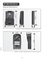
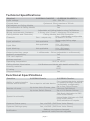
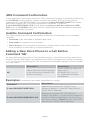
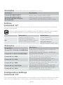
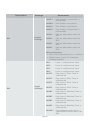
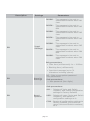
G-SPEAK Installation Manual TM GSM-BASED INTERCOM SYSTEM Company Profile Company Profile 1986 In-house R&D development team 100% testing of products 1990 1995 1999 Centurion Systems today Manufacture to international quality standard ISO 9001:2008 Competent after-sales technical support from 07h00 - 18h00 Monday to Friday Sales and support throughout Southern Africa and over 50 countries worldwide Centurion Systems (Pty) Ltd reserves the right to make changes to the products described in this manual without notice and without obligation of Centurion Systems (Pty) Ltd to notify any persons of any such revisions or changes. Additionally, Centurion Systems (Pty) Ltd makes no representations or warranties with respect to this manual. No part of this document may be copied, stored in a retrieval system or transmitted in any form or by any means electronic, mechanical, optical or photographic, without the express prior written consent of Centurion Systems (Pty) Ltd. Contents Quick Setup Steps page 1 IMPORTANT SAFETY INSTRUCTIONS page 2 1. 2. Glossary of Terms General Description Main Features 3. Specifications Physical Dimensions Technical Specifications Functional Specifications 4. Product Identification 5. Required Tools and Equipment 6. Mounting Instructions Calling Module Mounting GSM Controller Mounting Inserting an Activated SIM Card 7. Wiring Diagrams 8. GSM Network Signal Detection 9. G-SPEAK Functionality Voice Phone Functionality Adjusting the Calling Module Volume Switch Phone Functionality Changing the Default Password Resetting the Password to Default List Of Commands Special Commands 10. Installation Handover Page 4 Page 5 Page 5 Page 6 Page 6 Page 7 Page 7 Page 8 Page 10 Page 10 Page 10 Page 15 Page 16 Page 19 Page 21 Page 22 Page 22 Page 23 Page 24 Page 24 Page 24 Page 24 Page 32 Page 34 Icons used in this manual This icon indicates tips and other information that could be useful during the installation. This icon denotes variations and other aspects that should be considered during installation. This icon indicates warning, caution or attention! Please take special note of critical aspects that MUST be adhered to in order to prevent injury. Quick Setup Steps These abbreviated instructions are for the experienced installer who needs a checklist to get a standard installation up and running in the minimum of time. Detailed installation features and functions are referred to later in this manual. Mount the Calling Module according to the instructions given in the Installation section. Connect the GSM Controller to the Calling Module according to the wiring diagram in the Wiring section. Insert a network and RICA-registered SIM card (with some airtime loaded onto it) into the SIM card holder on the GSM Controller as shown on page 18. Connect a 12V - 30V DC power supply to the GSM Controller according to the instructions in the Wiring section. The backlight on the Calling Module will light up, and the GSM Controller will begin network registration. Once registered on the network, the Calling Module will emit three short beeps. Signal strength will be indicated on the signal strength LEDs next to the antenna connector as shown under Section 7. Program the unit. See Section 10. Call a Voice Phone and gauge voice quality and volume. It is important that the Calling Module and phone being called are separated by at least 20 meters to prevent feedback. Determine if any interference is noticeable during a call. Adjust the antenna placement to resolve any interference issues. The antenna should not be placed close to the Calling Module. page 1 IMPORTANT Safety Instructions ATTENTION To ensure the safety of people, it is important that you read all the following instructions. Incorrect installation or incorrect use of the product could cause serious harm to people. The installer, being either professional or DIY, is the last person on the site who can ensure that the operator is safely installed, and that the whole system can be operated safely. Warnings for the Installer CAREFULLY READ AND FOLLOW ALL INSTRUCTIONS before beginning to install the product. All installation, repair, and service work to this product must be carried out by a suitably qualified person Secure all easily accessed controls in order to prevent unauthorised use of the device Do not in any way modify the components of the G-SPEAK unit Do not install the G-SPEAK unit in an explosive atmosphere: the presence of flammable gasses or fumes is a serious danger to safety Before attempting to install the unit, cut electrical power to the control box where the G-SPEAK unit will be mounted Make sure that the earthing system is correctly constructed, and that all metal parts of the system are suitably earthed Explain these safety instructions to all persons authorised to use G-SPEAK, and be sure that they understand the hazards associated with the G-SPEAK system Do not leave packing materials (plastic, polystyrene, etc.) within reach of children as such materials are potential sources of danger Dispose of all waste products like packaging materials, worn-out batteries, etc. according to local regulations Centurion Systems does not accept any liability caused by improper use of the product, or for use other than that for which the automated system was intended page 2 This product was designed and built strictly for the use indicated in this documentation. Any other use, not expressly indicated here, could compromise the service life/operation of the product and/or be a source of danger Anything not expressly specified in these instructions is not permitted. page 3 1. Glossary of Terms Called Party: When one of the Call Buttons on the Calling Module is pressed, the Called Party is the person or persons who receives/answers the call on their mobile phone or landline handset. Calling Module: This can be seen as similar to a traditional intercom gate station or entry oanel that resides outside of the property and is the component of the G-SPEAK system that is used to dial through to and communicate with Voice Phones. GSM Controller: A module using GSM (Global System for Mobile Communications) technology to communicate wirelessly with GSM-enabled handsets, allowing both audible communication and monitoring and switching of inputs and outputs. DTMF: Dual Tone Multi-Frequency signalling. This is used for telecommunication signalling over analogue telephone lines in the voice-frequency band between telephone handsets and other communication devices and the switching centre. This allows the user to press 1, 2, 3 or 4 on his handset to switch any of the outputs on the G-SPEAK. Voice Phone: A Voice Phone pertains specifically to the intercom functionality of the G-SPEAK system, and is any learned-in phone with the ability to communicate audibly with the Calling Module, but is also capable of activating any of the outputs during a call using DTMF signalling. Switch Phone: A Switch Phone is a learned-in phone that is capable of exercising some influence upon the outputs of the controller via GSM switching and does not necessarily possess Voice Phone functionality, though it can be learned in for both. Channel: An electrical gateway implemented as a physical terminal on the G-SPEAK that provides the external interface to input or output signals. Hang Time: The time for which the call remains connected after a DTMF event. Filter Time: Filter Time is defined as the minimum time that the signal must be asserted before it is seen as valid. For example, if an input is configured to send a notification upon a falling signal being asserted – say, when mains power to an irrigation system fails – and the Filter Time has been set to ten seconds, the notification will only be sent if the falling edge signal has been present for at least ten seconds. Blanking Time: This refers to the minimum or ‘cool down’ period before an asserted input will respond to any subsequent assertions. For example, an input’s Blanking Time has been set to one hour and the input gets asserted and sends an SMS notification. One minute later, the input is asserted again. This second assertion will be ignored until an hour has passed. page 4 2. General Description The G-SPEAK Classic and G-SPEAK Classic+ are GSM-based intercom systems with advanced functionality. The system comprises two components, namely a Calling Module, which is typically mounted on the wall or a gooseneck outside the property, and a GSM Controller that is typically mounted inside the property, typically inside a gate motor housing. The two components are connected to each other via six wires, and allow communication between a visitor at the Calling Module and the homeowner’s phone through the use of GSM (Global System for Mobile Communications) technology. Main Features 1. Communicate wirelessly With the G-SPEAK range of audio GSM intercoms, the user’s mobile phone or landline becomes the handset, resulting in a significant saving in installation costs. This functionality enables the user to answer the intercom and open the gate from anywhere in the world with GSM network coverage. Two independent LED-backlit call buttons can be used to call up to four* pre-programmed landline or mobile phone numbers. 2. Control up to four devices Once the call is connected, the Called Party can activate up to four* different outputs using DTMF (Dual-Tone Multi-Frequency) signalling. This means that the user can, for example, open the gate for a visitor by pressing the number 1 key on his phone, or press 2 to open the pedestrian gate, etc. 3. Configurable channels Each output can be independently configured for either pulsed or latching operation, and the pulse time is configurable per output. This is useful in cases where the gate needs to be kept open for a period of time, for example to allow a truck or car and trailer into the property. The unit can be programmed to allow up to 100* users to activate one of the outputs via a Missed Call from their phone. In addition, the G-SPEAK Classic+ allows each of the four channels to be configured as either an input or an output – when configured as an input, a pre-defined SMS can be sent to selected users upon input activation and inputs also allow for Filter and Blanking times to be set. 4. Multiple user settings Configurable ring and call durations allow the unit to be customised to an individual’s needs, and volume at the Calling Module can be set by using the Call Buttons. See page 24 for detailed instructions. 5. High-security features The unit can also be used as a listening-in device* to survey the area around the Calling Module (usually located outside the property). When this functionality is used, the Calling Module speaker is muted. 6. User-friendly terminals The innovative design of the Calling Module’s spring-loaded terminals makes wiring quick, easy and entirely hassle-free. Simply use a terminal screwdriver to push the mechanism down, insert the wire and release. The wire will be held securely in place. Depends on model (G-SPEAK Classic allows one number per Call Button, plus one output with ten users; while G-SPEAK Classic+ allows two numbers per Call Button, plus four input/outputs with 100 users.) page 5 3. Specifications 120mm 116mm Physical Dimensions www.centsys.com 67mm 33mm 20mm FIGURE 1. OVERALL DIMENSIONS FOR GSM CONTROLLER 32mm 138mm 74mm FIGURE 2. OVERALL DIMENSIONS FOR THE CALLING MODULE page 6 Technical Specifications Physical G-SPEAK CLASSIC G-SPEAK CLASSIC+ 10V - 30V DC Input voltage Quiescent 30mA maximum 300mA Current draw Two Call buttons on Calling Module Yes Call confirmation at Calling Module Adjustable at Calling Module using Call Buttons Speech volume 6 wires, min 0.2mm²; Maximum 10m between Wiring requirements (between Calling Module and GSM Controller Calling Module and Controller) Four - individually configurable Channels One - output only as either In or Out Rising edge/falling edge Not applicable Input activation /both 0.1s - 24 hours Not applicable Input filter (in milliseconds) 0.1s - 24 hours Not applicable Input blanking (in milliseconds) Output pulse time range 1 milliseconds - 24hrs (adjustable in milliseconds) Network compatibility SIM card required Airtime required Operating temperature Calling Module illumination Housing material IP rating Surge protection Yes Yes Yes -20°C to +50°C Call Buttons and labels with backlit white LEDs ABS IP55 Yes Functional Specifications Function Ability to switch/monitor devices and functions Number of users Special functionality G-SPEAK Classic G-SPEAK Classic+ Four inputs/outputs to activate One output to activate device or monitor devices /functions (individually configurable) Up to four Voice Phones Up to two Voice Phones, plus (two per Call Button) Up to ten Switch Phones Up to 100 Switch Phones Talk Mode (Activate via SMS from Voice Phone) Listen Mode (Activate via SMS from Voice Phone) SMS activation of outputs Systems Status query Yes, via SMS (SMS from Voice Phone) Systems Settings query Yes, via SMS (SMS from Voice Phone) Notification Battery-low/volume changed/ password reset/firmware upgrade page 7 4. Product Identification 1 4 5 2 3 FIGURE 3. GSM CONTROLLER INTERIOR 1. 2. 3. 4. 5. GSM Module Input/output terminals SIM card holder Voice communications terminals Antenna page 8 1 2 3 4 5 FIGURE 4. CALLING MODULE INTERIOR 1. 2. 3. 4. 5. Speaker Voice communication terminals Call Button 1 Call Button 2 Microphone page 9 5. Required Tools and Equipment Screwdriver – 3.5mm flat Side cutter Drill bits – 5mm masonry; 6mm drill bit Silicone sealant Fasteners and rawl plugs Six metres of n6 core communication cable 6. Mounting Instructions Important Considerations All users calling or sending an SMS to the Module need to ensure that their Caller Line Identification Presentation (CLIP) is activated on their phone to ensure that the Module recognises the user’s learned-in phone number If a contract SIM card is being used in the Module itself, CLIP must also be enabled on that SIM card. This can be done by first inserting the SIM card into a mobile phone and enabling CLIP Ensure that the SIM card in the GSM Module does not have Call Forwarding enabled The SIM card in the GSM Module must have the PIN (Personal Identification Number) code disabled Calling Module Mounting Wall mounting recommendations Position the Calling Module on wall adjacent to entrance gate or door Mount at a height that allows for comfortably speaking into the microphone A typically recommended height is shown in Figure 5 Calling Module 1600mm FIGURE 5. Gooseneck mounting recommendations Ensure that the Calling Module does not protrude too far into the driveway The Calling Module must not be set too far back and must be easily accessed from a vehicle The height should allow for comfortably speaking into the microphone Calling Module FIGURE 6. page 10 18mm Dimensions of the Calling Module base and mounting holes relative to the Calling Module cover 110mm 138mm Dimensions 74mm FIGURE 7. Mounting Instructions Lift Calling Module cover 1. Lift off the outer cover of the Calling Module as shown in Figure 8. FIGURE 8. Screwdriver Calling Module 2. Insert screwdriver as shown and unclip the Calling Module from base. Calling Module base FIGURE 9. page 11 Calling Module 3. Lift the Calling Module off base. Calling Module base 4. Hold the Calling Module base against the wall at the required height, ensuring that it is vertical. FIGURE 10. 5. Mark the location of the mounting holes. Rawlplug 6. Using a 5mm masonry bit, drill holes into the wall for the rawlplugs provided in the kit. Calling Module 7. If the cable is being routed into the unit from a concealed conduit behind the base, knock out one of the cable entry holes provided in the base and feed through the cable. Ensure that at least 100mm of cable extends out of the wall. Mounting hole Sealing washer Mounting screw Cable 8. Fit sealing washer onto the mounting screw before installing as shown in Figure 11. 9. Screw the base firmly into position and using the slots provided in the mounting holes, adjust the base to be perfectly vertical. 10. Ensure that sealing washer is fitted and closes off the mounting hole to prevent water ingress as shown in Figure 12. FIGURE 11. Sealing washer Mounting screw FIGURE 12. page 12 Calling Module 11. Run the cable through the Calling Module base and then hook the Calling Module into the base as shown in Figure 13 and clip back into position. Cable Calling Module base FIGURE 13. 12. Terminate cable onto the voice communication terminal. Refer to wiring diagram in Figure 30 for details. Voice communication terminals Cable FIGURE 14. 13. If the cable is surface-mounted, route the cable into the unit from underneath as shown and terminate onto the voice communication terminal. Refer to the wiring diagram in Figure 33 for details. 14. Write Call Button labels, insert into lens(es) and clip lens(es) back onto chassis as shown in Figure 15. Voice communication terminals Lens Cable Labels FIGURE 15. page 13 Calling Module cover 15. Clip the outer cover back into position. It will be necessary when commissioning the unit to have the cover removed. FIGURE 16. 16. Secure the cover using the fixing screw provided in kit. Screw FIGURE 17. page 14 GSM Controller Mounting The GSM Controller will typically be housed inside the enclosure of the device it is to control, for instance a gate motor. However, it can be mounted onto a wall or other structure by following the instructions below: GSM Controller 1. Insert screwdriver into slot on the GSM Controller and twist. Slot Screwdriver FIGURE 18. Cover 2. Remove the cover and unclip and remove the circuit board from the retaining clips. Circuit board FIGURE 19. Mounting surface 3. Mark position of the unit against the mounting surface. Fastener 4. Using a 5mm masonry bit, drill a hole into mounting surface. 5. Mount the unit using suitable fasteners. Mounting hole FIGURE 20. page 15 6. Use a 6mm drill bit to open the required cable entry hole. Cable entry hole 6mm drill bit FIGURE 21. Ensure sufficient cable is provided for to reach the terminals of both the I/O terminals and the voice communication terminals Cover 7. Fix the cable to the wall using cable saddles. 8. Seal all the holes with silicone sealant. 9. Re-insert the circuit board and ensure that the retaining clips are holding it in place Cable saddles Power cable CircuitVoice board communication cable FIGURE 22. Inserting an Activated SIM Card Ensure that the activated SIM card going into the Module for the first time is not PIN protected 1. Slide the SIM card housing’s locking mechanism up to release the housing. Do not use a screwdriver to open the SIM Card locking mechanism. FIGURE 23. page 16 2. Raise the SIM card housing as shown in Figure 24. FIGURE 24. 3. Insert the activated SIM card and ensure that the SIM card is correctly oriented. Align the cropped corner to be in the correct position as per the diagram on the circuit board. Cover Circuit board FIGURE 25. 4. Once the SIM card is inserted correctly in the SIM card housing, lower the housing onto the circuit board. Then slide the SIM card housing locking mechanism down to ensure that the SIM card housing is securely locked in place. Do not use a screwdriver to close the SIM Card locking mechanism. FIGURE 26. page 17 GSM controller cover 5. Hook the top of the edge of the cover onto the top of the unit. 6. Lower the cover and press securely into position. FIGURE 27. page 18 7. Wiring Diagrams P3 P4 P5 Data communication lines P6 I03 GND 12V-24V Power supply 10V - 30V DC GND I02 Inputs/outputs 1 and 2 I04 I03 Inputs/outputs 3 and 4 P2 P1 G-SPEAK P3 P4 P5 P6 Data communication lines P2 P1 FIGURE 28. GSM CONTROLLER FIGURE 29. CALLING MODULE page 19 Solenoid lock GND 12V-24V P2 P5 I03 P4 P3 P5 103 P4 GND 102 P6 103 P3 104 GND I02 P2 P1 P1 I04 I03 P6 GND 12V-24V GSM controller P1 D5-Evo P5 P4 P3 Description Colour Power + and Call Power - and Call Speaker 1 Speaker 2 Mic 1 Mic 2 Calling Module P6 Terminal P1 P2 P3 P4 P5 P6 P2 Use the table below for colour allocation when connecting the wires It is recommended that 0.5mm2 multi-stranded shielded cable is used FIGURE 30. WIRING DIAGRAM page 20 8. GSM Network Signal Detection When powered up, the G-SPEAK will beep three times and the signal strength indicator LEDs will light up indicating the GSM network signal strength. The GSM signal strength can be determined based upon the combination of the three LEDs that illuminate: 3 5 2 3 1 1 4 LEDs 2 Signal strength indicator FIGURE 31. GSM MODULE The GSM signal strength may be enhanced by repositioning the antenna. Ideally the antenna should be mounted externally, and away from any sensitive electrical components. The rear side of the antenna has a double-sided tape backing, which may be used to affix the antenna to a desirable location. Please ensure that the surface to which you affix the antenna is smooth, clean and dry, to ensure reliable adhesion Illuminated LEDs 3 2+3 2 1+2 1 Signal strength 5/5 4/5 3/5 2/5 1/5 Antenna Adhesive cover 10. Power up the Module, hold the antenna and locate a position where there is optimum GSM signal. Remove the adhesive cover at the back of the antenna and mount. Keep the antenna away from the microphone FIGURE 32 page 21 9. G-SPEAK Functionality www.centsys.com FIGURE 33. The G-SPEAK range offers both voice and signalling functionality, each of which provides its own unique feature-set and capabilities including communication, switching and monitoring. The units are programmed via SMS command strings sent from a standard mobile phone. Categories of Learned-in Phones A clear distinction must be made between a Voice Phone and a Switch Phone. Voice Phone A Voice Phone pertains specifically to the intercom functionality of the G-SPEAK system, and is any learned-in phone with the ability to communicate by voice with the Calling Module, but is also capable of activating any of the outputs during a call using DTMF signalling. Switch Phone A Switch Phone is a learned-in phone that is capable of exercising some influence upon the outputs of the controller via GSM switching and does not necessarily possess Voice Phone Functionality, though it can be learned-in for both. Both of these unique operating modes are discussed in more detail in the sections that follow. Voice Phone Functionality The Calling Module has two Call Buttons. Each button is associated with either one Voice Phone in the case of the G-SPEAK Classic, or two Voice Phones in the case of the G-SPEAK Classic+, where at least one of which will need to be programmed before the unit can be used to initiate a call (refer to the List of Commands). When a Call Button is pressed, the Calling Module will emit either a call tone to indicate that a call is being initiated, or three low-pitched beeps to indicate that no number is associated with that Call Button. page 22 There will be a delay of up to ten seconds while the call connects, after which a ringtone will be heard from the Calling Module. Once answered by the Called Party, the call will end after either: 1. The call duration has expired (the default call duration is 30 seconds). 2. The call is terminated by pressing either of the Call Buttons on the Calling Module. 3. The call is terminated by the Called Party. 4. The hang time (the time for which the call remains connected before disconnecting after a DTMF tone) expires. The default hang time is 15 seconds. Three beeps from the Calling Module indicate that the call has ended. While the call is in progress, the Called Party can activate the one output on the G-SPEAK Classic, or any of the four outputs on the G-SPEAK Classic+ by pressing 1, 2, 3 or 4 on their phone keypad. This DTMF event will trigger the hang timer, and the call will automatically terminate after the hang time has expired, regardless of the call duration up to that point. Three configurable call parameters can be customised by the user (see List of Commands): 1. Call duration – The maximum call length (Range 10 seconds - 60 seconds, default is 30 seconds). 2. Ring time – The time for which the Called Phone will ring before the Calling Module disconnects (G-SPEAK Classic), or tries the second number (G-SPEAK Classic+) (range 10 seconds – 60 seconds, default 15 seconds). 3. Hang time – The time for which the call remains connected after a DTMF event (range 2 seconds - 30 seconds, default is 15 seconds). Adjusting the Calling Module volume The Calling Module volume can be changed (between 10% and 80%) by following these steps: 1. Press both Call Buttons simultaneously, 2. Wait for two beeps. 3. Use the Call Button 1 to increase the volume (10% per press), or Call Button 2 to decrease the volume (10% per press). On each press, a beep will be heard with the new volume. 4. When done, press both buttons again simultaneously (or wait 30 seconds). 5. The Calling Module will beep twice, and an SMS will be sent to the first Voice Phone number assigned to Button 1, indicating that the volume has been changed. page 23 Switch Phone Functionality The GSM Controller has capacity for ten Switch Phone numbers in the case of the G-SPEAK Classic, or 100 Switch Phone numbers in the case of the G-SPEAK Classic+, each of which can activate one or more (in the case of the G-SPEAK Classic+) outputs by Missed Call or SMS. Numbers are added using the AP command (see, List of Commands). These numbers are not to be confused with the Voice numbers referred to in the Voice Functionality section. A user’s number can be programmed as both a Voice Phone and a Switch Phone. Voice Phone Switch Phone Voice communication with mobile Yes No Switches outputs via DTMF (phone keypad during call) Missed call, SMS Receives notification of No input activation Yes (G-SPEAK Classic+ only) Receives notification of Yes (Any Voice number subscribed to system notification) password reset No Receives notification of Yes (Any Voice number subscribed to system notification) firmware upgrade No Yes (G-SPEAK Classic+ only) No Talk Yes (G-SPEAK Classic+ only) No Settings Yes No Listen Changing the Default Password The G-SPEAK leaves the factory with a default password of 1234. The password is used to prevent unauthorised users from changing settings, and adding new numbers. It is recommended that the default password is changed (see List of Commands in this section), and a record stored in a safe place. Resetting the Password to Default If the password is forgotten, it may be reset to 1234 by removing power from the unit, bridging the inner pins of the bootloader header with a suitable terminal jumper, and powering up. Remove the jumper, and wait for the LEDs to go off – an SMS will be sent to the first Voice Phone learned into Button 1, indicating that the password has been reset to 1234. List of Commands (for SMS configuration and administration of the controller) The following command sets may be used to SMS the respective configuration settings to the controller. The SMSs will need to be sent to the number of the SIM card in the controller. In the examples on the next page, ‘xxxx’ represents the Controller’s password(see Changing the Default Password) page 24 SMS Command Confirmation If you would like confirmation that your SMS command has been successfully received by the G-SPEAK, simply append a space and then the letters ‘ACK’ to the end of the command set in the SMS message. For example: P.xxxx.AB.0821234567 will simply add phone number 082 123 4567 and assigns it to Button 1; however, P.xxxx.AB.0821234567 ACK will do the same but you will also receive an SMS back from the G-SPEAK that reads ‘AB OK’ confirming that the Add Button command has been successfully executed. Audible Command Confirmation The Calling Module will also provide audible feedback and confirmation of commands received: One beep if the command is accepted and valid Two beeps if a syntax error is present Three beeps if the command is sent from a number that is not a Voice number or if the command is sent with an incorrect password Adding a New Voice Phone to a Call Button Command ‘AB’ As described in the Voice Phone Functionality section, a Voice Phone will be called when either of the two Call Buttons are pressed and is able to activate the outputs by pressing 1, 2, 3 or 4 on the phone keypad. This command set essentially assigns a phone number to a Call Button. AB Examples Description Parameters Adds a new Voice Phone number to be called when a specific Call Button is pressed Phone number(s) (up to 16 digits each) Call Button BU (1 or 2) N – Subscribe to System Notifications (commands have been highlighted for clarity) Command Description P.xxxx.AB.0821234567.BU1 Adds phone number 082 123 4567 and assigns to Button 1. Does NOT add phone to Switch Phone database. P.xxxx.AB.0821234568.BU1.2.N Adds phone number 082 123 4568 and assigns it to Button 1 as the second number to be called. System Notifications will be sent to this Voice number. (Classic+ only). Does NOT add phone to Switch Phone database. page 25 Retrieve List of Voice Phone Numbers Assigned to a Call Button Command ‘LB’ Description Lists the Voice numbers assigned to each button LB Examples Parameters None (commands have been highlighted for clarity) Command Description P.xxxx.LB Sends an SMS to the originating number listing the Voice Phone numbers assigned to each button Adding a New Switch Phone Command ‘AP’ As described in the Switch Phone Functionality Section, a Switch Phone is able to activate any of the controller’s outputs via a Missed Call (both models) or SMS (Classic+ only). Any of the Switch Phones, where configured, can turn on or off any of the outputs by sending the text message OUx ON or OUx OFF to the G-SPEAK (the ‘x’ in the command string represents the output number referred to). If configured, the output name can be used instead of OUx. Turning on a pulsed output will cause it to trigger, while turning it off will have no effect. Example: Output 1 of a G-SPEAK Classic+ has been assigned the name ALARM (using the command string documented in the Configuration Settings section). The output can be activated by sending an SMS with the text ‘ALARM ON’ (no quotation marks) to the device from a Switch Phone configured for SMS activation. Likewise, the output can be deactivated (the alarm disarmed) by sending an SMS with the text ‘ALARM OFF’ (no quotation marks) to the unit. Description Parameters Phone number(s) (up to 16 digits each) Output to be activated via a Missed Call (OU1/OU2/OU3/OU4) AP Adds a new Switch Phone to activate the controller’s output(s) via a Missed Call or SMS (Classic+ only) Output to be activated via an SMS (OU1S/OU2S/OU3S/OU4S) Input event to be monitored (IN1R/F/B, IN2 R/F/B, IN3 R/F/B, IN4 R/F/B) Rising or falling input event, G-SPEAK Classic+ only page 26 (R, F, or B) Examples (commands have been highlighted for clarity) Description Command P.xxxx.AP.0821234567 P.xxxx.AP.0821234567.OU2 P.xxxx.AP.0821234567. 0821234568.0821234569. 0821234566.OU3 P.xxxx.AP.0841234567.OU2.OU4 P.xxxx.0821234567.OU1. OU2S.IN1R Adds phone number 082 123 4567 and, since no output is specified, automatically assigns it to activate Output 1 Adds phone number 082 123 4567 and assigns it to activate Output 2 Add phone numbers 0821234566, 0821234567, 0821234568 and 0821234569 and assign all to activate Output 3 via a Missed Call Adds phone number 0841234567 to the system, and assigns Output 2 and Output 4 to be activated by a Missed Call Configures Output 1 to react to Missed Calls and Output 2 to react to SMSs, and subscribes the number 082 123 4567 to receive SMS notifications when Input 1 rises Deleting a Voice Phone Command ‘DB’ This command deletes all Voice Phone numbers assigned to specific Call Buttons from the system, i.e. it stops a number from being called when a button is pressed. DB Examples Description Parameters Removes the specified Voice Phones assigned to Call Buttons from the system. Phone number(s) (up to 16 digits each) Call Button BU (1 or 2) (commands have been highlighted for clarity) Command Description P.xxxx.DB.BU1 Delete and clear all Voice Phones assigned to Button 1 P.xxxx.DB.BU2.1 Deletes only Voice Phone number 1 from Button 2 Deleting a Switch Phone Command ‘DP’ This command allows one or more Switch Phone numbers to be deleted from the system. DP Description Parameters Removes the specified Switch Phones from the system Phone number(s) (up to 16 digits each) page 27 Examples (commands have been highlighted for clarity) Command Description P.xxxx.DP.0821234567 Delete phone number 0821234567 P.xxxx.DP.0821234567. 0821234568.0821234569. 0821234566 Delete phone numbers 0821234567, 0821234568, 0821234569 and 0821234566 Airtime Command ‘AT’ This command allows an airtime voucher to be loaded onto the controller, or remaining airtime to be queried. Since a voice transaction is initiated once a Call Button is pressed, there needs to be sufficient airtime on the controller SIM card at any given stage. AT Examples Description Parameters Loads or queries airtime. Requires knowledge of the network specific USSD codes for airtime recharge and query. Load airtime (L) Query airtime (Q) Sub-parameters: Network specific USSD code (commands have been highlighted for clarity) Command Description P.xxxx.AT.L.*100*01*1234567890# Loads airtime voucher number 1234567890 onto a Vodacom SIM card P.xxxx.AT.L.*102*1234567890# Loads airtime voucher number 1234567890 onto an MTN SIM card P.xxxx.AT.Q.*100# P.xxxx.AT.Q.*141# P.xxxx.AT.Q.*188# P.xxxx.AT.Q.*111*502# P.xxxx.AT.Q.*101# Airtime remaining on the Vodacom SIM card is sent via SMS to the querying device Airtime remaining on the MTN SIM card is sent via SMS to the querying device Airtime remaining on the 8ta SIM card is sent via SMS to the querying device Will reply back with airtime, SMS and data bundle balances on the Vodacom SIM card Airtime remaining on the Cell C SIM card is sent via SMS to the querying device Configuration Settings Command ‘CO’ This command allows the functionality of the system to be configured. Outputs and inputs can be set up (dependent on the model), call settings edited, passwords managed, etc. page 28 More than one configuration setting can be applied/edited using a single SMS by separating the commands with a full stop. In the case of the G-SPEAK Classic+ all I/Os (configurable inputs and outputs) are defaulted as outputs and may be reconfigured to be inputs, whereas the G-SPEAK Classic only has one output which cannot be configured to be an input. Where channels have been set up to act as inputs only (G-SPEAK CLASSIC+ only), further parameters can be set by specifying Filter and Blanking Times. Filter and Blanking Time(G-SPEAK CLASSIC+ only) Filter Time is defined as the minimum time that the signal must be asserted before it is seen as valid. For example, if an input is configured to send a notification upon a falling edge signal being asserted – say, when mains power to an irrigation system fails – and the Filter Time has been set to ten seconds, the notification will only be sent if the falling edge signal has been present for at least ten seconds. Blanking Time, on the other hand, refers to the minimum or ‘cool down’ period before an asserted input will respond to any subsequent assertions. For example, an input’s Blanking Time has been set to one hour and the input gets asserted and sends an SMS notification. One minute later, the input is asserted again. This second assertion will be ignored until an hour has passed. Description Settings Parameters CT (Call Time) – Sets the maximum duration of the call (the call can be terminated earlier by either party) RT (Ring Time)– Sets the time before which the unit will disconnect if a call is unanswered CO Configure inputs, outputs and system Call settings HT (Hang Time) – Sets the time for which the call remains connected after a DTMF event Sub-parameters: Call time (seconds) Ring time (seconds) Hang time (seconds) OU1PU – Sets Output 1 as pulsed OU1LA – Sets Output 1 as latched OU1PT – Sets Output 1 pulse time in milliseconds CO Output Settings OU2PU – Sets Output 2 as pulsed OU2LA – Sets Output 2 as latched OU2PT – Sets Output 2 pulse time in milliseconds OU3PU – Sets Output 3 as pulsed OU3LA – Sets Output 3 as latched page 29 Description Settings Parameters OU3PT – Sets Output 3 pulse time in milliseconds OU4PU – Sets Output 4 as pulsed OU4LA – Sets Output 4 as latched OU4PT – Sets Output 4 pulse time in milliseconds CO Output Settings OU1N – Sets an alternative name for OU1 OU2N – Sets an alternative name for OU2 OU3N – Sets an alternative name for OU3 OU4N – Sets an alternative name for OU4 Sub-parameters: Pulse time (milliseconds) 1s = 1000ms CO Input Settings Output name (up to 31 characters including spaces) IN1 – Input 1 configured as input IN2 – Input 2 configured as input IN3 – Input 3 configured as input IN4 – Input 4 configured as input IN1FT – Sets Input 1 Filter Time in milliseconds IN2FT – Sets Input 2 Filter Time in milliseconds IN3FT – Sets Input 3 Filter Time in milliseconds IN4FT – Sets Input 4 Filter Time in milliseconds IN1BT – Sets Input 1 Blanking Time in milliseconds IN2BT – Sets Input 2 Blanking Time in milliseconds IN3BT – Sets Input 3 Blanking Time in milliseconds IN4BT – Sets Input 4 Blanking Time in milliseconds IN1FM – The message to be sent to subscribed numbers when IN1 falls page 30 Description Settings Parameters IN1RM – The message to be sent to subscribed numbers when IN1 rises IN2FM – The message to be sent to subscribed numbers when IN2 falls AT IN2RM – The message to be sent to subscribed numbers when IN2 rises IN3FM – The message to be sent to subscribed numbers when IN3 falls CO Input Settings IN3RM – The message to be sent to subscribed numbers when IN3 rises IN4FM – The message to be sent to subscribed numbers when IN4 falls IN4RM – The message to be sent to subscribed numbers when IN4 rises Sub-parameters: Filter time (milliseconds) 1s = 1000ms Blanking time (milliseconds) Input text message (up to 31 characters including spaces) NP – Sets a new system password Sub-parameters: CO Security Settings Sub-parameters: New password (four digits) Sub-parameters: ALL – Deletes all Voice and Switch numbers, and resets configuration settings to Factory Defaults CO Reset Options USR – Deletes all users (Voice and Switch numbers), and leaves all configuration settings as is CON – Resets all configuration settings to Factory Defaults, and leaves all users (Voice and Switch numbers) as is page 31 Examples (commands have been highlighted for clarity) Command Description P.xxxx.CO.NP.1333 Changes the current system password to 1333 P.xxxx.CO.CT.30 Sets the maximum call duration to 30 seconds P.xxxx.CO.OU1PT.2000 Sets the pulse time of Output 1 to 2000ms (2s) P.xxxx.CO.OU1LA.OU2PU. OU2PT.5000 Configures Output 1 for latching operation, sets Output 2 to be a pulsed output and sets the pulse time to 5000ms (5s) P.xxxx.CO.IN1.IN2.IN1FT. 500.IN1BT.30000 P.XXXX.CO.IN3.IN3FM. “MAINS FAIL” P.xxxx.CO.RESET.ALL P.xxxx.CO.RESET.USR P.xxxx.CO.RESET.CON P.xxxx.CO.OU3.GATE TRIGGER Configures Channel 1 and Channel 2 as inputs, and sets the Input 1 Filter Time and Blanking Time to 500ms and 30000ms respectively Configures Channel 3 as an input and sets the message to be sent to subscribed numbers when Input 3 falls as “MAINS FAIL” Deletes all Voice Phone and Switch Phone numbers, and resets configuration settings to Factory Defaults Deletes all users (Voice Phone and Switch Phone numbers), and leaves all configuration settings as is Resets all configuration settings to factory defaults, and leaves all users (Voice Phone and Switch Phone numbers) as is Changes the name of Output 3 to GATE TRIGGER Commands can be concatenated, i.e. multiple commands sent in a single SMS, by simply separating the commands with a space. Command Description P.xxxx.CO.OU1LA DB.BU2.1 Configures Output 1 as a latching output AND deletes Voice Phone number 1 from Button 2 P.xxxx.CO.NP.4545 AT.L. *100*01*5686299345# Changes the system password to 4545 AND loads airtime voucher number 5686299345 onto a Vodacom SIM card page 32 Special Commands Any of the Voice Numbers can text the G-SPEAK with four special messages (depending on the G-SPEAK model) to activate the following functions: Command LISTEN TALK STATUS SETTINGS Description By SMSing ‘LISTEN’ to the G-SPEAK, the G-SPEAK will mute the speaker on the Calling Module, and call the phone that sent the SMS, allowing the Called Party to listen in on what is happening at the Calling Module. Anyone at the Calling Module will be unaware that a call is in progress and that they are being listened to. DTMF functionality is available during this call, allowing the Called Party to activate any of the outputs by pressing 1, 2, 3 or 4 on their phone keypad. In addition, pressing* or # will reset the call duration timer, extending the call by the call duration time. By SMSing ‘TALK’ to the G-SPEAK, the G-SPEAK will call the phone that sent the command, allowing the Called Party to talk to anyone at the Calling Module. DTMF functionality is available during this call, allowing the Called Party to activate any of the outputs by pressing 1,2,3 or 4 on their phone keypad. In addition, pressing* or # will reset the call duration timer, extending the call by the call duration time. By SMSing ‘STATUS’ to the G-SPEAK, the G-SPEAK will send an SMS to the phone that sent the STATUS command, indicating firmware version, serial number, signal strength, input and output states, etc. By SMSing ‘SETTINGS’ to the G-SPEAK, the G-SPEAK will send an SMS to the phone that sent the SETTINGS command, indicating system settings. Classic+ only * G-SPEAK The Called Party will hear an alert tone ten seconds before the call timer expires page 33 10. Installation Handover Once the installation has been successfully completed and tested, it is important for the installer to explain the operation and safety requirements of the system. Centurion Systems (Pty) Ltd does not accept any liability caused by improper use of the product, or for use other than that for which the automated system was designed. page 34 Sharecall 0860-CENTURION (0860 236 887) Head Office: +27 11 699 2400 Sharecall Technical Support 0861 003 123 or +27 11 699 2481 from 07h00 to 18h00 (GMT+2) (Sharecall numbers applicable when dialled from within South Africa only) 0.07.A.0190_27012014 www.CentSys.com