1
Theory of Operation
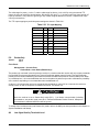
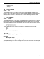
During the receiver signal acquisition process, the proper RF signal is acquired and then the channel and network
identifiers are matched against the user's predetermined configuration within the receiver. When these match, the
Sync and Enable indicators are illuminated. However, if either of the IDs do not match, an acquisition network ID
fault <FL 31> is declared and the acquisition process continues until the correct signal is received.
If the network and channel ID information stops for a period of thirty seconds, a network ID timeout fault <FL 30>
is generated.
It is important that the channel and network ID numbers generated at the codec/mux match the
receiver configuration. For example, if a channel ID of 16 is used at the uplink, then all downlink
ABR receivers must have channel configuration #16 defined for the proper RF receiver
frequency, symbol rate, and demodulation type i.e., <CC 16,11700000,128000,1>.
If another channel configuration number is used, say “CC 1”, in any receiver, those receivers configured with “CC
1” instead of “CC 16” will not acquire the signal properly and will not operate. For multiple carriers from a single
uplink the network ID should be the same for all codec/muxes, but the channel IDs must be unique (i.e., 1, 2, 3,
etc.).
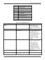
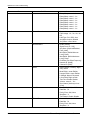
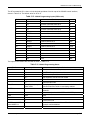
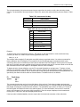
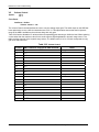
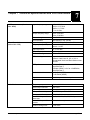
An example of several different possible combinations of channel identifiers and frequency allocations are
provided in Table 2-3 (assuming QPSK operation and 128 kbps transmission rate)
Table 2.4 Channel Identifier & Frequency Allocation Combinations
Carrier No.
Uplink Site
RF Freq MHz
NI
CI
CC/FD Format (at ABRs)
A
X
11,700.0
2
1
CC 1,...
FD 1,2,1,7
B
Y
11,700.2
1
1
CC 1,...
FC1,1,1,7
C
Z
11,701.0
1
2
CC 2,...
FC 2,1,2,7
FC 3,1,2,5
D
Z
11,701.2
1
3
CC 3,...
FD 4,1,3,7
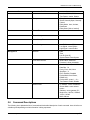
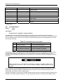
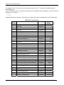
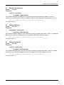
If you add a fifth carrier, Carrier E (shown in Table 2-4), to the configuration of carrier frequencies and ID numbers
in Table 2-3, it is possible that carriers B and E would be incorrectly received, since they are within 600 kHz of
each other and do not have unique ID numbers. All other carriers would operate properly
Table 2.5 Carrier B and E Channel Identifier and Frequency Allocation
Carrier No.
Uplink Site
RF Freq MHz
NI
CI
CC/FD Format (at ABRs)
B
Y
11,700.2
1
1
CC 1,...
FD 1,1,1,7
E
Z
11,700.8
1
1
CC 1,...
FC1,1,1,7
2.3.2 Low Noise Block (LNB) Downconverter
The LNB downconverter takes the satellite signals at C- or Ku-band and block downconverts them to L-band for
processing by the satellite receiver. The performance of the LNB downconverter is critical, as it establishes the
noise figure for the entire receiver system. A block diagram of the LNB subsystem is shown in Figure 2-6
2-18
Tiernan Family of Audio Broadcast Receivers