1
Contents
Controls and Connectors ..................................
Dimensions ........................................................
AC Power ...........................................................
Audio Input ........................................................
Limiting and Protection Circuitry .....................
Rigging ...............................................................
Complete Systems .............................................. 8
Verifying Polarity ............................................... 10
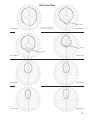
Coverage Angles and Polar Plots ..................... 11
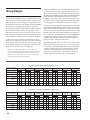
Array Design ...................................................... 14
Safety Summary ................................................ 15
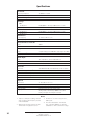
Specifications .................................................... 16
3
3
4
5
6
7
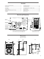
Controls and Connectors
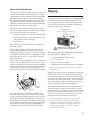
!
!
WARNINGS:
THIS PRODUCT MUST BE GROUNDED
This surface may reach high temperatures while in use.
To ensure proper operation, allow at least 6 inches
clearance from this surface and adequate ventilation.
To reduce the risk of electric shock do not remove cover.
No operator serviceable parts inside.
Refer servicing to qualified personnel.
To reduce the risk of fire or electric shock
do not expose this appliance to rain or moisture.
Mains circuit
breakers
Input Polarity
ENTRETIEN ET REPARATIONS
INTERNES NE SONT AUTORISEES QU'AU
PERSONNEL TECHNIQUE QUALIFIÉ
GEHÄUSE NICH
UND REPARATUR NUR DURC
THIS APPARATUS MUST BE EARTHED.
NO OPERATOR SERVICEABLE PARTS INSIDE.
REFER SERVICING TO QUALIFIED PERSONNEL
ATTENTION : ENTRETIEN E
INTERNES NE SONT AUTORIU
PERSONNEL TECHNIQUE QUA
IRK
UK WARNING :
THIS APPA
NO OPERATOR SERVICEABLE P
REFER SERVICING TO QUALIFIE
PUSH
Auto-Voltage Selec
10A RMS
20A Peak
88-127V
50-60Hz
700W RMS MAX
3+
Auto-Voltage Select
95-125V
208-235V
50-60Hz
50-60Hz
1400W RMS MAX 1400W RMS MAX
~
~
~
1
3
2
2
Earth / Chassis
Remote Monitoring
System panel
(if RMS is installed)
et
e
k
ic
in
rv
es
Se
R
Loop
W
Input
A
ct
iv
ity
3
1
1
3
Se
Network
Input
rv
ic
e
Monitoring
System
A
ct
iv
ity
~
~
Network
Loop
Remote
Remote
Operational voltage
Turn on 80V
Tu
Turn on 160V
Tu
2
et
1
k
1
in
3
es
2
R
220K Ω
W
ESD
Case
Signal input and
loop connectors
-C
UK WARNING :
Balanced
Input polarity switch
ACHTUNG :
S
PU H
-I T
-I T
IRK
PUSH
2+
ACCESO INTER
AUTORIZADO A PERSONAL T
IRK
ATTENTION :
RE
RE
-C
-C
-I T
-I T
GEHÄUSE NICHT ÖFFNEN WARTUNG
UND REPARATUR NUR DURCH ELEKTROFACHKRÄFTE
S
PU H
Active / Speaker Fault
RE
RE
LO Limit
ATENCIÓN :
S
PU H
ACHTUNG :
IRK
HI Limit
10K Ω
Tie-wrap anchor
ACCESO INTERNO SOLO
AUTORIZADO A PERSONAL TÉCNICO CALIFICADO
S
PU H
-C
Power LED (green/red)
This surface may reach high t
To ensure proper operation, allow
clearance from this surface and a
To reduce the risk of electric sho
No operator serviceable parts ins
Refer servicing to qualified perso
To reduce the risk of fire or elect
do not expose this appliance to r
Mains AC inlet
ATENCIÓN :
CQ
High Limit (red)
Low Limit (red)
WARNINGS:
THIS PRODUCT M
Monitor
System
Meyer Sound, Berkeley, CA. USA
Meyer Sound, Be
Rear User Panel shown with the optional
Remote Monitoring System (RMS) panel
European Rear User Panel
with IEC 309 connector
Dimensions
All units in inches
Front
Side
Top
2.0"
20.50"
21.0"
9.55"
2.0"
20.5"
9.55"
30.0"
13.55"
21.0"
14.26"
15.25"
3